


Data sheet
Thermostatic expansion valves
Type TE 5 – TE 55
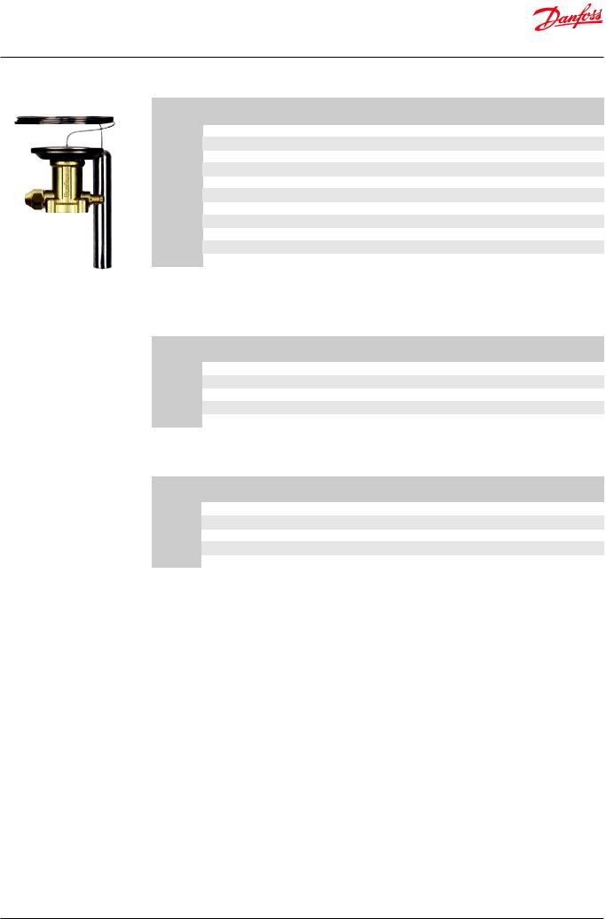
The TE 5 - TE 55 series expansion valve regulate the injection of refrigerant into evaporators.
It controls the refrigerant flow based on the superheat. The exchangeable power element is produced with the well known Danfoss laser welding technology for extended lifetime
capability. The TE 5 - TE 55 series is available with a wide range of orifices which will cover a wide range of applications.
Applications:
- Air conditioning system - Chiller
- Cold room - Freezer
- Other refrigeration systems
Features |
• |
Wide operating range: |
|
|
|
-40 |
– 10 °C / -40 – 50 °F |
|
|
-60 |
– -25 °C / -75 – -15 °F |
|
• Refrigerants: R407F, R407A, R448A, R449A, |
||
|
|
R452A,R404A, R507, R22, R513A, R134a and |
|
|
|
R407C. |
|
|
• |
Interchangeable orifice assembly: |
|
- easy storage
- easy capacity matching - better service
• Wide capacity range, rated capacity from:
R448A/R449A |
: 9 – 225 kW / 2.5 – 64 TR |
R407F |
: 11 – 250 kW / 3 – 71 TR |
R404A/R507 |
: 7 – 183 kW / 2 – 52 TR |
•MOP function is available.
•Superior charge performance.
•PS / MWP (maximum working pressure): 28 bar / 400 psig.
•Minimized capacity gap and overlap between orifices.
•Laser welded stainless steel power element, capillary tube and bulb.
•TE 55 has balanced port design.
•Patented bulb strap design.
© Danfoss | DCS (sw) | 2019.01 |
DKRCC.PD.AB0.A7.02 | 1 |
Data sheet | Thermostatic expansion valves, type TE 5 – TE 55
Technical data |
Max. temperature |
Max. test pressure: 32 bar / 465 psig. |
|
Bulb, when valve is assembled:100 °C / 210 °F. |
Maximum working pressure: 28 bar / 400 psig. |
|
Complete valve when not assembled: 70 °C / 160 °F. |
|
|
Min. temperature: -60 °C / -75 °F. |
|
MOP-points |
|
|
|
|
SI units |
|
|
|
|
|
|
US units |
|
Range |
Range |
Range |
|
Range |
|
Range |
|
Range |
Range |
|
Range |
|
-40 − 10 °C |
-40 − -5 °C |
-40 − -15 °C |
|
-60 − -25 °C |
|
-40 – 50 °F |
|
-40 – 25 °F |
-40 – 5 °F |
|
-75 – -15 °F |
Refrigerant |
MOP-point in evaporating temperature te |
|
MOP-point in evaporating temperature te |
|||||||||
|
|
and evaporating pressure pe |
|
|
|
and evaporating pressure pe |
|
|||||
|
15 °C |
0 °C |
-10 °C |
|
-20 °C |
|
60 °F |
|
32 °F |
15 °F |
|
-5 °F |
R407F/R407A |
7.5 bar |
4.2 bar |
2.6 bar |
|
1.5 bar |
|
110 psig |
|
60 psig |
40 psig |
|
20 psig |
R404A/R507 |
8.6 bar |
5.1 bar |
3.4 bar |
|
2.0 bar |
|
120 psig |
|
70 psig |
45 psig |
|
30 psig |
R22 |
6.9 bar |
4.0 bar |
2.6 bar |
|
1.5 bar |
|
100 psig |
|
60 psig |
35 psig |
|
20 psig |
R134a |
3.9 bar |
2.0 bar |
1.0 bar |
|
0.3 bar |
|
55 psig |
|
30 psig |
15 psig |
|
5 psig |
R407C |
6.6 bar |
3.6 bar |
2.2 bar |
|
1.1 bar |
|
95 psig |
|
50 psig |
30 psig |
|
15 psig |
MOP = Max. Operating Pressure
For MOP of R448A/R449A, R452A, R513A, please contact Danfoss for more information.
Superheat |
SS |
|
= static superheat |
|
OS |
|
= opening superheat |
|
SH |
|
= SS + OS = total superheat |
|
Qnom |
= rated capacity |
|
|
Qmax |
= maximum capacity |
|
|
SS can be adjusted with setting spindle. |
||
|
The standard factory SS setting is 4 K / 7.2 °F. |
||
|
The OS is 4 K / 7.2 °F from when opening begins to |
||
|
where the valve reaches its rated capacity Qnom. |
||
|
OS is determined by the design and cannot be |
||
|
changed. |
||
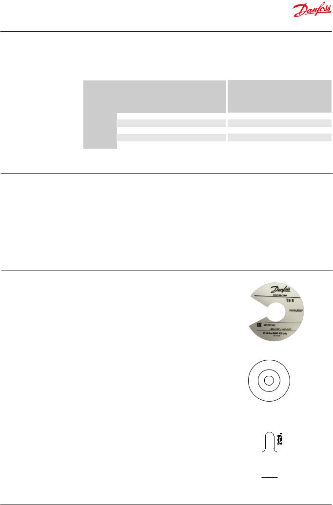
Identification |
The thermostatic element is fitted with a label (on |
||
|
top of the diaphragm). |
||
|
The label holds information like valve type, |
||
|
evaporating temperature range, MOP point, |
||
|
refrigerant, max. working pressure PS / MWP and |
||
|
production date. |
||
|
Production place and date (BE1315B) mean: |
||
|
BE |
= Wuqing, China |
|
|
13 |
= Week |
|
|
15 |
= Year 2015 |
|
|
B |
= Tuesday |
|
|
Orifice assembly for TE 5 – TE 55 |
||
|
The orifice assembly is marked on top of the |
||
|
spring cup, e.g. as shown in the figure. |
||
|
TE 12 |
= For valve type |
|
|
06 |
|
= Orifice no. |
|
067B2709 = Orifice code no. for sales order |
||
|
1315 |
= week 13, year 2015 |
|
Capillary tube tag for TE 5 – TE 55
The label gives the orifice size (06). A new label always accompanies a new orifice assembly.
Example |
|
|
Static superheat |
SS |
= 4 K / 7.2 °F |
Opening superheat |
OS |
= 4 K / 7.2 °F |
Total superheat |
SH |
= 4 + 4 = 8 K |
|
SH |
= 7.2 + 7.2 = 14.4 °F |
Using orifice with range B element, please check superheat under running conditions and readjust SS setting, if necessary.
Element label
|
|
|
2 |
06 |
M |
|
|
|||
|
|
1 |
|
|
|
A |
|
|
||
|
E |
|
|
|
|
|
D |
|||
5 |
T |
|
|
|
|
|
|
E |
||
1 |
|
|
|
|
|
|
|
|
|
N |
|
|
|
|
|
|
|
|
|
I |
|
3 |
|
|
|
|
|
|
|
|
C |
|
9 |
|
|
|
|
|
|
|
|||
|
|
|
|
|
|
|
H |
|||
1 |
|
|
|
|
|
|
|
|
|
|
|
|
|
|
|
|
|
|
|
I |
|
0 |
|
|
|
|
N |
|
||||
|
|
7 |
|
|
|
A |
|
|
||
|
|
|
|
2 |
|
|
|
|
|
|
|
|
|
|
|
B76 |
|
|
|
|
|
|
|
|
|
|
|
0 |
|
|
|
|
Orifice assembly marking for TE 5 – TE 55
 6
6 
Capillary tube tag
TE 5 – TE 55
© Danfoss | DCS (sw) | 2019.01 |
DKRCC.PD.AB0.A7.02 | 2 |

Data sheet | Thermostatic expansion valves, type TE 5 – TE 55
Design / Function |
General |
|
|
TE 5 – TE 55 valves have an interchangeable |
|
|
orifice assembly. |
|
|
TE 5 – TE 55 valves are built up of three main |
|
|
components (Parts program): |
|
|
1. |
Thermostatic element |
|
2. |
Orifice assembly |
|
3. |
Valve body with connections |
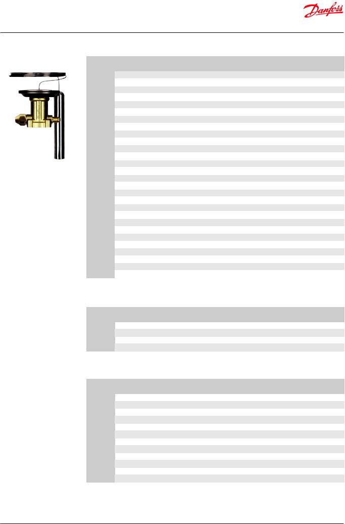
1. Thermostatic
element
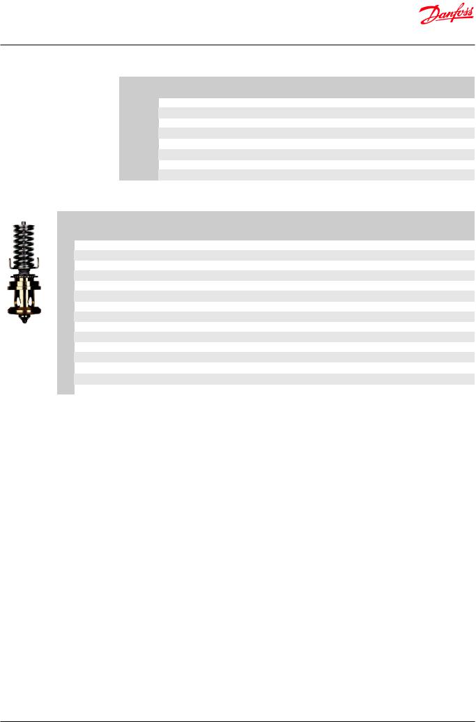
2.Orifice assembly
3.Valve body with connections
The orifice is refrigerant and range independend.
All valves are equipped with external pressure equalization.
To ensure long operating life, the valve cone and seat are made of a special alloy with particularly good wear properties.
1.Thermostatic element.
2.Interchangeable orifice assembly.
3.Valve body.
4.Superheat setting spindle.
5.External pressure equalizing
connection with 1⁄4 in / 6 mm flare nut (solder is available on TE 5).
 1
1
 5 4
5 4
 2
2
 3
3
Danfoss 67B53.10
TE 5
 1
1
 5 4
5 4  3
3
2
Danfoss 68B53.10
TE 12 / TE 20
 1 5
1 5
 4
4
 2
2
 3
3
Danfoss 67B52.10
TE 55
© Danfoss | DCS (sw) | 2019.01 |
DKRCC.PD.AB0.A7.02 | 3 |
Data sheet | Thermostatic expansion valves, type TE 5 – TE 55
Ordering |
Element for expansion valve - including bulb strap. |
|
|
|
R407F/R407A |
||||||
|
|
|
|
||||||||
|
Valve type |
Pressure equalization |
|
MOP |
Range |
Capillary tube |
Code no. |
||||
|
Size |
Type |
[°C] |
|
[°F] |
[°C] |
[°F] |
[m] |
[in] |
||
|
|
|
|
||||||||
|
|
1/4 in / 6 mm |
Flare |
– |
|
– |
-40 – 10 |
-40 – 50 |
3 |
118 |
067B3501 |
|
TE 5 |
1/4 in / 6 mm |
Flare |
0 |
|
32 |
-40 – -5 |
-40 – 25 |
3 |
118 |
067B3502 |
|
1/4 in / 6 mm |
Flare |
-10 |
|
15 |
-40 – -15 |
-40 – 5 |
3 |
118 |
067B3503 |
|
|
|
|
|||||||||
|
|
1/4 in |
Solder ODF |
– |
|
– |
-40 – 10 |
-40 – 50 |
3 |
118 |
067B3504 |
|
|
1/4 in / 6 mm |
Flare |
– |
|
– |
-40 – 10 |
-40 – 50 |
3 |
118 |
067B3532 |
|
TE 12 |
1/4 in / 6 mm |
Flare |
0 |
|
32 |
-40 – -5 |
-40 – 25 |
3 |
118 |
067B3531 |
|
|
1/4 in / 6 mm |
Flare |
-10 |
|
15 |
-40 – -15 |
-40 – 5 |
3 |
118 |
067B3533 |
|
|
1/4 in / 6 mm |
Flare |
– |
|
– |
-40 – 10 |
-40 – 50 |
3 |
118 |
067B3561 |
|
TE 20 |
1/4 in / 6 mm |
Flare |
0 |
|
32 |
-40 – -5 |
-40 – 25 |
3 |
118 |
067B3560 |
|
|
1/4 in / 6 mm |
Flare |
-10 |
|
15 |
-40 – -15 |
-40 – 5 |
3 |
118 |
067B3562 |
|
TE 55 |
1/4 in / 6 mm |
Flare |
– |
|
– |
-40 – 10 |
-40 – 50 |
3 |
118 |
067G3500 |
Element for expansion valve - including bulb strap. |
|
|
|
R448A/R449A |
|||||||
Valve type |
|
Pressure equalization |
|
MOP |
Range |
Capillary tube |
Code no. |
||||
|
Size |
Type |
[°C] |
|
[°F] |
[°C] |
[°F] |
[m] |
[in] |
||
|
|
|
|
||||||||
TE 5 |
1⁄4 in. / 6 mm |
Flare |
– |
|
– |
-40 – 10 |
-40 – 50 |
3 |
118 |
067B3252 |
|
1⁄4 |
in. / 6 mm |
Flare |
-20 |
|
-5 |
-60 – -25 |
-75 – -15 |
3 |
118 |
067B3600 |
|
|
|
||||||||||
TE 12 |
1⁄4 |
in. / 6 mm |
Flare |
– |
|
– |
-40 – 10 |
-40 – 50 |
3 |
118 |
067B2512 |
TE 20 |
1⁄4 |
in. / 6 mm |
Flare |
– |
|
– |
-40 – 10 |
-40 – 50 |
3 |
118 |
067B3294 |
TE 55 |
1⁄4 |
in. / 6 mm |
Flare |
– |
|
– |
-40 – 10 |
-40 – 50 |
3 |
118 |
067G3219 |
Element for expansion valve - including bulb strap. |
|
|
|
|
R452A |
|||||
Valve type |
Pressure equalization |
|
MOP |
Range |
Capillary tube |
Code no. |
||||
|
|
|
|
|
|
|
|
|
||
Size |
Type |
[°C] |
|
[°F] |
[°C] |
[°F] |
[m] |
[in] |
||
|
|
|
||||||||
TE 5 |
1⁄4 in. / 6 mm |
Flare |
– |
|
– |
-40 – 10 |
-40 – 50 |
3 |
118 |
067B3601 |
1⁄4 in. / 6 mm |
Flare |
-20 |
|
-5 |
-60 – -25 |
-75 – -15 |
3 |
118 |
067B3602 |
|
|
|
|||||||||
TE 12 |
1⁄4 in. / 6 mm |
Flare |
– |
|
– |
-40 – 10 |
-40 – 50 |
3 |
118 |
067B3652 |
TE 20 |
1⁄4 in. / 6 mm |
Flare |
– |
|
– |
-40 – 10 |
-40 – 50 |
3 |
118 |
067B3680 |
TE 55 |
1⁄4 in. / 6 mm |
Flare |
– |
|
– |
-40 – 10 |
-40 – 50 |
3 |
118 |
067G3600 |
© Danfoss | DCS (sw) | 2019.01 |
DKRCC.PD.AB0.A7.02 | 4 |

Data sheet | Thermostatic expansion valves, type TE 5 – TE 55
Ordering |
|
|
|
|
|
|
|
|
|
R404A/R507 |
||
|
Element for expansion valve - including bulb strap. |
|
|
|
||||||||
|
Valve type |
Pressure equalization |
|
MOP |
|
Range |
Capillary tube |
Code no |
||||
|
|
|
|
|
|
|
|
|
|
|
||
|
Size |
Type |
[°C] |
|
[°F] |
|
[°C] |
[°F] |
[m] |
[in] |
||
|
|
|
|
|
||||||||
|
|
|
|
|
|
|
|
|
|
|
|
|
|
|
1/4 in / 6 mm |
Flare |
– |
|
– |
|
-40 – 10 |
-40 – 50 |
3 |
118 |
067B3342 |
|
|
1/4 in |
Solder ODF |
– |
|
– |
|
-40 – 10 |
-40 – 50 |
3 |
118 |
067B3380 |
|
|
1/4 in / 6 mm |
Flare |
15 |
|
60 |
|
-40 – 10 |
-40 – 50 |
3 |
118 |
067B3238 |
|
|
1/4 in / 6 mm |
Flare |
0 |
|
32 |
|
-40 – -5 |
-40 – 25 |
3 |
118 |
067B3357 |
|
TE 5 |
1/4 in / 6 mm |
Flare |
-10 |
|
15 |
|
-40 – -15 |
-40 – 5 |
3 |
118 |
067B3358 |
|
1/4 in |
Solder ODF |
-10 |
|
15 |
|
-40 – -15 |
-40 – 5 |
3 |
118 |
067B3384 |
|
|
|
|
|
|||||||||
|
|
1/4 in / 6 mm |
Flare |
– |
|
– |
|
-60 – -25 |
-75 – -15 |
3 |
118 |
067B3344 |
|
|
6 mm |
Solder ODF |
– |
|
– |
|
-60 – -25 |
-75 – -15 |
3 |
118 |
067B3392 |
|
|
1/4 in / 6 mm |
Flare |
-20 |
|
-5 |
|
-60 – -25 |
-75 – -15 |
3 |
118 |
067B3343 |
|
|
1/4 in |
Solder ODF |
-20 |
|
-5 |
|
-60 – -25 |
-75 – -15 |
3 |
118 |
067B3381 |
|
|
1/4 in / 6 mm |
Flare |
– |
|
– |
|
-40 – 10 |
-40 – 50 |
3 |
118 |
067B3347 |
|
|
1/4 in / 6 mm |
Flare |
0 |
|
32 |
|
-40 – -5 |
-40 – 25 |
3 |
118 |
067B3345 |
|
|
1/4 in / 6 mm |
Flare |
-10 |
|
15 |
|
-40 – -15 |
-40 – 5 |
3 |
118 |
067B3348 |
|
TE 12 |
1/4 in / 6 mm |
Flare |
-20 |
|
-5 |
|
-60 – -25 |
-75 – -15 |
3 |
118 |
067B3349 |
|
|
1/4 in / 6 mm |
Flare |
– |
|
– |
|
-60 – -25 |
-75 – -15 |
3 |
118 |
067B3368 |
|
|
1/4 in / 6 mm |
Flare |
– |
|
– |
|
-40 – 10 |
-40 – 50 |
5 |
197 |
067B3346 |
|
|
1/4 in / 6 mm |
Flare |
-20 |
|
-5 |
|
-60 – -25 |
-75 – -15 |
5 |
197 |
067B3350 |
|
|
1/4 in / 6 mm |
Flare |
– |
|
– |
|
-40 – 10 |
-40 – 50 |
3 |
118 |
067B3352 |
|
|
1/4 in / 6 mm |
Flare |
0 |
|
32 |
|
-40 – -5 |
-40 – 25 |
3 |
118 |
067B3351 |
|
TE 20 |
1/4 in / 6 mm |
Flare |
-10 |
|
15 |
|
-40 – -15 |
-40 – 5 |
3 |
118 |
067B3353 |
|
1/4 in / 6 mm |
Flare |
-20 |
|
-5 |
|
-60 – -25 |
-75 – -15 |
3 |
118 |
067B3354 |
|
|
|
|
|
|||||||||
|
|
1/4 in / 6 mm |
Flare |
– |
|
– |
|
-40 – 10 |
-40 – 50 |
5 |
197 |
067B3356 |
|
|
1/4 in / 6 mm |
Flare |
-20 |
|
-5 |
|
-60 – -25 |
-75 – -15 |
5 |
197 |
067B3355 |
|
|
1/4 in / 6 mm |
Flare |
– |
|
– |
|
-40 – 10 |
-40 – 50 |
3 |
118 |
067G3302 |
|
|
1/4 in / 6 mm |
Flare |
0 |
|
32 |
|
-40 – -5 |
-40 – 25 |
3 |
118 |
067G3303 |
|
TE 55 |
1/4 in / 6 mm |
Flare |
-10 |
|
15 |
|
-40 – -15 |
-40 – 5 |
3 |
118 |
067G3304 |
|
1/4 in / 6 mm |
Flare |
-20 |
|
-5 |
|
-60 – -25 |
-75 – -15 |
3 |
118 |
067G3305 |
|
|
|
|
|
|||||||||
|
|
1/4 in / 6 mm |
Flare |
– |
|
– |
|
-40 – 10 |
-40 – 50 |
5 |
197 |
067G3301 |
|
|
1/4 in / 6 mm |
Flare |
-20 |
|
-5 |
|
-60 – -25 |
-75 – -15 |
5 |
197 |
067G3306 |
© Danfoss | DCS (sw) | 2019.01 |
DKRCC.PD.AB0.A7.02 | 5 |
Data sheet | Thermostatic expansion valves, type TE 5 – TE 55
Ordering |
Element for expansion valve - including bulb strap. |
|
|
|
|
|
|
|
R22/R407C 1) |
||||||
|
Valve type |
Pressure equalization |
|
MOP |
Range |
|
|
Capillary tube |
Code no. |
||||||
|
|
|
|
|
|
|
|
|
|
|
|
|
|
||
|
Size |
Type |
[°C] |
|
[°F] |
[°C] |
[°F] |
|
|
[m] |
|
|
[in] |
||
|
|
|
|
|
|
|
|
||||||||
|
|
1/4 in / 6 mm |
Flare |
– |
|
– |
-40 – 10 |
-40 – 50 |
3 |
118 |
067B3250 |
||||
|
|
1/4 in |
Solder ODF |
– |
|
– |
-40 – 10 |
-40 – 50 |
3 |
118 |
067B3420 |
||||
|
|
1/4 in / 6 mm |
Flare |
15 |
|
60 |
-40 – 10 |
-40 – 50 |
3 |
118 |
067B3267 |
||||
|
TE 5 |
1/4 in / 6 mm |
Flare |
0 |
|
32 |
-40 – -5 |
-40 – 25 |
3 |
118 |
067B3249 |
||||
|
|
1/4 in / 6 mm |
Flare |
-10 |
|
15 |
-40 – -15 |
-40 – 5 |
3 |
118 |
067B3253 |
||||
|
|
1/4 in / 6 mm |
Flare |
– |
|
– |
-60 – -25 |
-75 – -15 |
3 |
118 |
067B3263 |
||||
|
|
1/4 in / 6 mm |
Flare |
-20 |
|
-5 |
-60 – -25 |
-75 – -15 |
3 |
118 |
067B3251 |
||||
|
|
1/4 in / 6 mm |
Flare |
– |
|
– |
-40 – 10 |
-40 – 50 |
3 |
118 |
067B3210 |
||||
|
|
1/4 in / 6 mm |
Flare |
– |
|
– |
-40 – 10 |
-40 – 50 |
5 |
197 |
067B3209 |
||||
|
|
1/4 in / 6 mm |
Flare |
15 |
|
60 |
-40 – 10 |
-40 – 50 |
3 |
118 |
067B3227 |
||||
|
TE 12 |
1/4 in / 6 mm |
Flare |
0 |
|
32 |
-40 – -5 |
-40 – 25 |
3 |
118 |
067B3207 |
||||
|
1/4 in / 6 mm |
Flare |
-10 |
|
15 |
-40 – -15 |
-40 – 5 |
3 |
118 |
067B3213 |
|||||
|
|
|
|||||||||||||
|
|
1/4 in / 6 mm |
Flare |
-20 |
|
-5 |
-60 – -25 |
-75 – -15 |
3 |
118 |
067B3211 |
||||
|
|
1/4 in / 6 mm |
Flare |
– |
|
– |
-60 – -25 |
-75 – -15 |
3 |
118 |
067B3225 |
||||
|
|
1/4 in / 6 mm |
Flare |
-20 |
|
-5 |
-60 – -25 |
-75 – -15 |
5 |
197 |
067B3212 |
||||
|
|
1/4 in / 6 mm |
Flare |
– |
|
– |
-40 – 10 |
-40 – 50 |
3 |
118 |
067B3274 |
||||
|
|
1/4 in / 6 mm |
Flare |
– |
|
– |
-40 – 10 |
-40 – 50 |
5 |
197 |
067B3290 |
||||
|
|
1/4 in / 6 mm |
Flare |
15 |
|
60 |
-40 – 10 |
-40 – 50 |
3 |
118 |
067B3286 |
||||
|
TE 20 |
1/4 in / 6 mm |
Flare |
0 |
|
32 |
-40 – -5 |
-40 – 25 |
3 |
118 |
067B3273 |
||||
|
|
1/4 in / 6 mm |
Flare |
-10 |
|
15 |
-40 – -15 |
-40 – 5 |
3 |
118 |
067B3275 |
||||
|
|
1/4 in / 6 mm |
Flare |
-20 |
|
-5 |
-60 – -25 |
-75 – -15 |
3 |
118 |
067B3276 |
||||
|
|
1/4 in / 6 mm |
Flare |
-20 |
|
-5 |
-60 – -25 |
-75 – -15 |
5 |
197 |
067B3287 |
||||
|
|
1/4 in / 6 mm |
Flare |
– |
|
– |
-40 – 10 |
-40 – 50 |
3 |
118 |
067G3205 |
||||
|
|
1/4 in / 6 mm |
Flare |
– |
|
– |
-40 – 10 |
-40 – 50 |
5 |
197 |
067G3209 |
||||
|
|
1/4 in / 6 mm |
Flare |
15 |
|
60 |
-40 – 10 |
-40 – 50 |
3 |
118 |
067G3220 |
||||
|
TE 55 |
1/4 in / 6 mm |
Flare |
0 |
|
32 |
-40 – -5 |
-40 – 25 |
3 |
118 |
067G3206 |
||||
|
|
1/4 in / 6 mm |
Flare |
-20 |
|
-5 |
-60 – -25 |
-75 – -15 |
3 |
118 |
067G3207 |
||||
|
|
1/4 in / 6 mm |
Flare |
-20 |
|
-5 |
-60 – -25 |
-75 – -15 |
5 |
197 |
067G3217 |
||||
|
1) For R407C plants. please select elements from the dedicated R407C program |
|
|
|
|
|
|
|
|
||||||
|
Element for expansion valve - including bulb strap. |
|
|
|
|
|
|
|
|
R513A |
|||||
|
Valve type |
Pressure equalization |
|
MOP |
Range |
|
|
Capillary tube |
Code no. |
||||||
|
Size |
Type |
[°C] |
|
[°F] |
[°C] |
[°F] |
|
|
[m] |
|
|
[in] |
||
|
|
|
|
|
|
|
|
||||||||
|
TE 5 |
1/4 in / 6 mm |
Flare |
– |
|
– |
-40 – 10 |
-40 – 50 |
|
3 |
|
118 |
067B3603 |
||
|
TE 12 |
1/4 in / 6 mm |
Flare |
– |
|
– |
-40 – 10 |
-40 – 50 |
|
3 |
|
118 |
067B3651 |
||
|
TE 20 |
1/4 in / 6 mm |
Flare |
– |
|
– |
-40 – 10 |
-40 – 50 |
|
3 |
|
118 |
067B3681 |
||
|
TE 55 |
1/4 in / 6 mm |
Flare |
– |
|
– |
-40 – 10 |
-40 – 50 |
|
3 |
|
118 |
067G3601 |
||
|
Element for expansion valve - including bulb strap. |
|
|
|
|
|
|
|
|
R134a |
|||||
|
Valve type |
Pressure equalization |
|
MOP |
Range |
|
|
Capillary tube |
Code no. |
||||||
|
|
|
|
|
|
|
|
|
|
|
|
|
|
||
|
Size |
Type |
[°C] |
|
[°F] |
[°C] |
[°F] |
|
|
[m] |
|
|
[in] |
||
|
|
|
|
|
|
|
|
||||||||
|
|
1/4 in / 6 mm |
Flare |
– |
|
– |
-40 – 10 |
-40 – 50 |
|
|
3 |
|
|
118 |
067B3297 |
|
TE 5 |
1/4 in |
Solder ODF |
– |
|
– |
-40 – 10 |
-40 – 50 |
|
3 |
|
118 |
067B3430 |
||
|
|
1/4 in / 6 mm |
Flare |
15 |
|
60 |
-40 – 10 |
-40 – 50 |
|
3 |
|
118 |
067B3298 |
||
|
|
1/4 in / 6 mm |
Flare |
– |
|
– |
-40 – 10 |
-40 – 50 |
|
|
3 |
|
|
118 |
067B3232 |
|
TE 12 |
1/4 in / 6 mm |
Flare |
15 |
|
60 |
-40 – 10 |
-40 – 50 |
|
3 |
|
118 |
067B3233 |
||
|
|
1/4 in / 6 mm |
Flare |
– |
|
– |
-40 – 10 |
-40 – 50 |
|
5 |
|
197 |
067B3363 |
||
|
|
1/4 in / 6 mm |
Flare |
– |
|
– |
-40 – 10 |
-40 – 50 |
|
|
3 |
|
|
118 |
067B3292 |
|
TE 20 |
1/4 in / 6 mm |
Flare |
15 |
|
60 |
-40 – 10 |
-40 – 50 |
|
3 |
|
118 |
067B3293 |
||
|
|
1/4 in / 6 mm |
Flare |
– |
|
– |
-40 – 10 |
-40 – 50 |
|
5 |
|
197 |
067B3370 |
||
|
|
1/4 in / 6 mm |
Flare |
– |
|
– |
-40 – 10 |
-40 – 50 |
|
|
3 |
|
|
118 |
067G3222 |
|
TE 55 |
1/4 in / 6 mm |
Flare |
15 |
|
60 |
-40 – 10 |
-40 – 50 |
|
|
3 |
|
|
118 |
067G3223 |
|
|
1/4 in / 6 mm |
Flare |
– |
|
– |
-40 – 10 |
-40 – 50 |
|
|
5 |
|
|
197 |
067G3230 |
© Danfoss | DCS (sw) | 2019.01 |
DKRCC.PD.AB0.A7.02 | 6 |
Data sheet | Thermostatic expansion valves, type TE 5 – TE 55
Ordering |
|
|
|
Element for expansion valve - including bulb strap. |
|
|
|
|
|
|
|
|
|
|
|
|
|
|
R407C |
||||||||||||||||||
|
|
|
|
|
|
|
|
|
|
|
|
|
|
|
|
|
|
|
|||||||||||||||||||
|
|
|
|
|
Valve type |
|
Pressure equalization |
|
|
|
MOP |
|
|
|
Range |
|
|
|
Capillary tube |
|
|
Code no. |
|
||||||||||||||
|
|
|
|
|
|
|
Size |
|
|
Type |
|
|
[°C] |
|
|
[°F] |
|
|
|
[°C] |
|
|
[°F] |
|
[m] |
[in] |
|
|
|
||||||||
|
|
|
|
|
|
|
|
|
|
|
|
|
|
|
|
|
|
|
|
|
|
|
|
|
|||||||||||||
|
|
|
|
|
TE 5 |
|
1/4 in / 6 mm |
|
|
Flare |
|
|
– |
|
|
– |
|
|
-40 – 10 |
|
-40 – 50 |
|
3 |
118 |
|
|
067B3278 |
|
|||||||||
|
|
|
|
|
|
1/4 in / 6 mm |
|
|
Flare |
|
|
15 |
|
|
60 |
|
|
|
-40 – 10 |
|
-40 – 50 |
|
3 |
118 |
|
|
067B3277 |
|
|||||||||
|
|
|
|
|
|
|
|
|
|
|
|
|
|
|
|
|
|
|
|
|
|||||||||||||||||
|
|
|
|
|
TE 12 |
|
1/4 in / 6 mm |
|
|
Flare |
|
|
– |
|
|
– |
|
|
-40 – 10 |
|
-40 – 50 |
|
3 |
118 |
|
|
067B3366 |
|
|||||||||
|
|
|
|
|
|
1/4 in / 6 mm |
|
|
Flare |
|
|
15 |
|
|
60 |
|
|
|
-40 – 10 |
|
-40 – 50 |
|
3 |
118 |
|
|
067B3367 |
|
|||||||||
|
|
|
|
|
|
|
|
|
|
|
|
|
|
|
|
|
|
|
|
|
|||||||||||||||||
|
|
|
|
|
|
|
|
1/4 in / 6 mm |
|
|
Flare |
|
|
– |
|
|
– |
|
|
-40 – 10 |
|
-40 – 50 |
|
5 |
197 |
|
|
067B3371 |
|
||||||||
|
|
|
|
|
TE 20 |
|
1/4 in / 6 mm |
|
|
Flare |
|
|
15 |
|
|
60 |
|
|
|
-40 – 10 |
|
-40 – 50 |
|
5 |
197 |
|
|
067B3372 |
|
||||||||
|
|
|
|
|
TE 55 |
|
1/4 in / 6 mm |
|
|
Flare |
|
|
– |
|
|
– |
|
|
-40 – 10 |
|
-40 – 50 |
|
5 |
197 |
|
|
067G3240 |
|
|||||||||
|
|
|
|
|
|
1/4 in / 6 mm |
|
|
Flare |
|
|
15 |
|
|
60 |
|
|
|
-40 – 10 |
|
-40 – 50 |
|
5 |
197 |
|
|
067G3241 |
|
|||||||||
|
|
|
|
|
|
|
|
|
|
|
|
|
|
|
|
|
|
|
|
|
|||||||||||||||||
|
Orifice for expansion valves. Rated capacity. |
|
|
|
|
|
|
|
|
|
|
|
|
|
|
|
|
|
|
|
|
|
|
|
|
|
|||||||||||
|
|
|
|
|
|
|
|
|
|
|
|
|
|
|
|
|
|
|
|
|
|
|
|
|
|
|
|
|
|
|
|
|
|
|
|
|
|
|
Valve |
Orifice |
R407F |
R407A |
R448A/ |
R452A |
R404A/ |
R22 |
R513A |
R134a |
R407C |
R407F |
R407A |
R448A/ |
R452A |
R404A/ |
R22 |
R513A |
R134a |
R407C |
|
|
|||||||||||||||
|
R449A |
|
R507 |
R449A |
R507 |
Code no. |
|
||||||||||||||||||||||||||||||
|
type |
no. |
|
|
|
|
|
|
|
|
|
|
|
|
|
|
|
|
|
|
|
|
|
|
|
|
|
|
|
|
|
|
|
|
|
|
|
|
|
|
|
|
|
|
[kW] |
|
|
|
|
|
|
|
|
|
|
|
|
|
|
|
|
|
[TR] |
|
|
|
|
|
|
|
|
|
|||
|
|
|
|
|
|
|
|
|
|
|
|
|
|
|
|
|
|
|
|
|
|
|
|
|
|
|
|
|
|
|
|
|
|
|
|||
|
|
|
|
|
|
|
|
|
|
|
|
|
|
|
|
|
|
|
|
|
|
|
|
|
|
|
|
|
|
|
|
|
|
|
|||
|
|
0.5 |
11 |
9 |
9 |
7 |
|
7 |
9 |
5 |
|
5 |
|
11 |
|
3 |
|
2.5 |
|
2.5 |
2 |
2 |
2.5 |
|
1.5 |
1.5 |
|
3 |
|
067B2788 |
|||||||
|
|
01 |
18 |
18 |
18 |
14 |
|
14 |
16 |
11 |
|
11 |
|
18 |
|
5 |
|
5 |
|
5 |
4 |
4 |
4.5 |
|
3 |
3 |
|
5 |
|
067B2789 |
|||||||
|
TE 5 |
02 |
28 |
25 |
25 |
21 |
|
19 |
25 |
14 |
|
16 |
|
25 |
|
8 |
|
7 |
|
7 |
6 |
5.5 |
7 |
|
4 |
4.5 |
|
7 |
|
067B2790 |
|||||||
|
|
03 |
35 |
32 |
32 |
28 |
|
25 |
32 |
18 |
|
21 |
|
32 |
|
10 |
|
9 |
|
9 |
8 |
7 |
9 |
|
5 |
6 |
|
9 |
|
067B2791 |
|||||||
|
|
04 |
46 |
42 |
46 |
39 |
|
35 |
42 |
25 |
|
28 |
|
46 |
|
13 |
|
12 |
|
13 |
11 |
10 |
12 |
|
7 |
8 |
|
13 |
|
067B2792 |
|||||||
|
|
05 |
70 |
56 |
53 |
46 |
|
49 |
56 |
30 |
|
35 |
|
53 |
|
20 |
|
16 |
|
15 |
13 |
14 |
16 |
|
8.5 |
10 |
|
15 |
|
067B2708 |
|||||||
|
TE 12 |
06 |
95 |
74 |
70 |
63 |
|
63 |
74 |
39 |
|
49 |
|
74 |
|
27 |
|
21 |
|
20 |
18 |
18 |
21 |
|
11 |
14 |
|
21 |
|
067B2709 |
|||||||
|
|
07 |
113 |
95 |
91 |
81 |
|
81 |
95 |
49 |
|
63 |
|
91 |
|
32 |
|
27 |
|
26 |
23 |
23 |
27 |
|
14 |
18 |
|
26 |
|
067B2710 |
|||||||
|
TE 20 |
08 |
141 |
127 |
123 |
84 |
|
84 |
127 |
74 |
|
77 |
|
116 |
|
40 |
|
36 |
|
35 |
24 |
24 |
36 |
|
21 |
22 |
|
33 |
|
067B2771 |
1) |
||||||
|
09 |
158 |
148 |
141 |
98 |
|
102 |
148 |
81 |
|
91 |
|
134 |
|
45 |
|
42 |
|
40 |
28 |
29 |
42 |
|
23 |
26 |
|
38 |
|
067B2773 |
1) |
|||||||
|
|
|
|
|
|
|
|
|
|
|
|||||||||||||||||||||||||||
|
|
9B |
123 |
109 |
113 |
84 |
|
84 |
113 |
70 |
|
74 |
|
109 |
|
35 |
|
31 |
|
32 |
24 |
24 |
32 |
|
20 |
21 |
|
31 |
|
067G2705 |
2) |
||||||
|
|
10 |
172 |
165 |
155 |
116 |
|
127 |
169 |
98 |
|
109 |
|
162 |
|
49 |
|
47 |
|
44 |
33 |
36 |
48 |
|
28 |
31 |
|
46 |
|
067G2701 |
|||||||
|
TE 55 |
11 |
186 |
183 |
169 |
127 |
|
137 |
183 |
106 |
|
120 |
|
176 |
|
53 |
|
52 |
|
48 |
36 |
39 |
52 |
|
30 |
34 |
|
50 |
|
067G2704 |
|||||||
|
|
|
|
|
|
|
|
|
|
|
|
|
|
|
|
|
|
|
|
|
|
|
|
|
|
|
|
|
|
|
|
|
|
|
|
|
|
|
|
12 |
208 |
200 |
186 |
141 |
|
151 |
200 |
116 |
|
134 |
|
190 |
|
59 |
|
57 |
|
53 |
40 |
43 |
57 |
|
33 |
38 |
|
54 |
|
067G2707 |
|||||||
|
|
13 |
250 |
243 |
225 |
172 |
|
183 |
246 |
144 |
|
165 |
|
232 |
|
71 |
|
69 |
|
64 |
49 |
52 |
70 |
|
41 |
47 |
|
66 |
|
067G2710 |
|||||||
|
The rated capacity is based on: |
|
|
|
|
|
|
|
|
|
|
|
|
|
|
|
|
|
|
|
|
|
|
|
|
|
|
|
|
|
|
|
|||||
|
Evaporating temperature |
|
|
|
te = 4.4 °C / 40 °F |
|
|
|
|
|
|
|
|
|
|
|
|
|
|
|
|
|
|
|
|
|
|
|
|||||||||
|
Condensing temperature |
|
|
|
tc |
= 38 °C / 100 °F |
|
|
|
|
|
|
|
|
|
|
|
|
|
|
|
|
|
|
|
|
|
|
|
||||||||
|
Refrigerant temperature ahead of valve tl |
= 37 °C / 98 °F |
|
|
|
|
|
|
|
|
|
|
|
|
|
|
|
|
|
|
|
|
|
|
|
||||||||||||
1) Recommend to use orifice no. 9B as alternative for orifice no. 08 and 09 on TE 55 when selecting the valve to work in range -60 – -25 °C / -75 – -15 °F.
Extend capacity tables for range -60 – -25 °C / -75 – -15 °F are not provided.
2) Alternative for orifice no. 08 and 09 in range -60 – -25 °C / -75 – -15 °F. Extend capacity tables for range -40 – 10 °C / -40 –50 °F are not provided.
© Danfoss | DCS (sw) | 2019.01 |
DKRCC.PD.AB0.A7.02 | 7 |
Data sheet | Thermostatic expansion valves, type TE 5 – TE 55
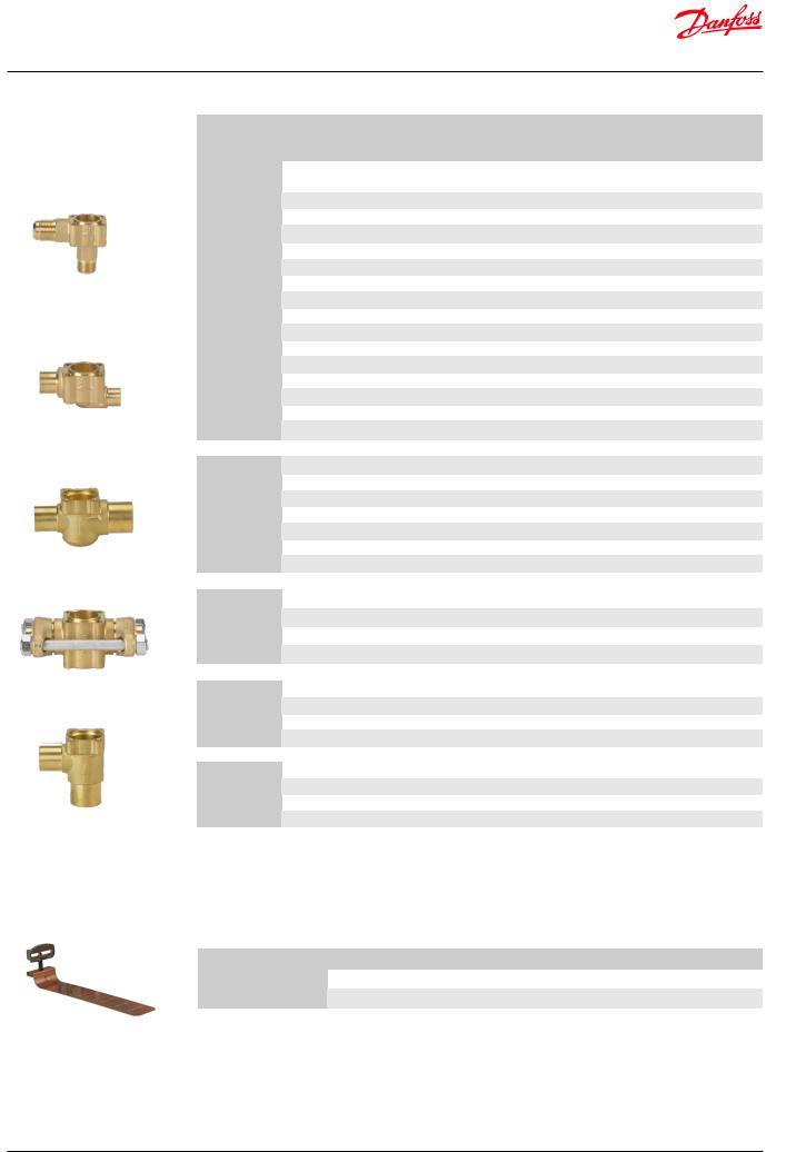
Ordering
Flare angleway
Solder straightway
Solder straightway
Flanges
Solder angleway
Spareparts
Valve body for expansion valves
|
|
|
|
|
|
|
Connection |
|
Connection |
|
||
Type |
|
|
|
|
Inlet × Outlet |
Connections / Flow direction |
Code no. |
|||||
|
|
|
|
type 1) |
||||||||
|
|
|
|
[in] |
|
|
|
[mm] |
|
|
||
|
|
|
|
|
|
|
|
|
|
|||
|
|
|
|
|
|
|
|
|
|
|
|
|
|
|
1/ |
2 |
× 5/ |
8 |
|
12 × 16 |
Flare angleway |
– |
067B4013 |
||
|
|
1/ |
2 |
× 5/ |
8 |
|
– |
Solder angleway |
ODF ×ODF |
067B4009 |
||
|
|
1/ |
2 |
× 7/ |
8 |
|
– |
Solder angleway |
ODF ×ODF |
067B4010 |
||
|
|
5/ |
8 |
× 7/ |
8 |
|
– |
Solder angleway |
ODF ×ODF |
067B4011 |
||
|
|
7/8 × 11/8 |
– |
Solder angleway |
ODF ×ODM |
067B4034 |
||||||
|
|
1/ |
2 |
× 5/ |
8 |
|
– |
Solder straightway |
ODF ×ODF |
067B4007 |
||
|
|
1/ |
2 |
× 7/ |
8 |
|
– |
Solder straightway |
ODF ×ODF |
067B4008 |
||
|
|
5/ |
8 |
× 7/ |
8 |
|
– |
Solder straightway |
ODF ×ODF |
067B4032 |
||
TE 5 |
|
7/ |
8 |
× 11/ |
8 |
– |
Solder straightway |
ODF ×ODM |
067B4033 |
|||
|
|
|
|
|
– |
|
|
|
12 × 16 |
Solder angleway |
ODF ×ODF |
067B4004 |
|
|
|
|
|
– |
|
|
|
12 × 22 |
Solder angleway |
ODF ×ODF |
067B4005 |
|
|
|
|
|
– |
|
|
|
16 × 22 |
Solder angleway |
ODF ×ODF |
067B4012 |
|
|
|
|
|
– |
|
|
|
22 × 28 |
Solder angleway |
ODF ×ODM |
067B4037 |
|
|
|
|
|
|
|
|
|
|
|
|
|
|
|
|
|
|
– |
|
|
|
12 × 16 |
Solder straightway |
ODF ×ODF |
067B4002 |
|
|
|
|
|
– |
|
|
|
12 × 22 |
Solder straightway |
ODF ×ODF |
067B4003 |
|
|
|
|
|
|
|
|
|
|
|
|
|
|
|
|
|
|
– |
|
|
|
16 × 22 |
Solder straightway |
ODF ×ODF |
067B4035 |
|
|
|
|
|
– |
|
|
|
22 × 28 |
Solder straightway |
ODF ×ODM |
067B4036 |
|
|
|
|
|
|
|
|
|||||
|
|
|
|
|
|
|
|
|
|
|
|
|
|
|
5/8 × 7/8 |
|
– |
Solder angleway |
ODF ×ODF |
067B4022 |
|||||
|
|
7/ |
8 |
× 11/ |
8 |
– |
Solder angleway |
ODF ×ODM |
067B4023 |
|||
|
|
5/ |
8 |
× 7/ |
8 |
|
– |
Solder straightway |
ODF ×ODF |
067B4020 |
||
TE 12 |
|
7/ |
8 |
× 11/ |
8 |
– |
Solder straightway |
ODF ×ODM |
067B4021 |
|||
|
|
|
|
|
– |
|
|
|
22 × 28 |
Solder angleway |
ODF ×ODM |
067B4017 |
|
|
|
|
|
– |
|
|
|
16 × 22 |
Solder straightway |
ODF ×ODF |
067B4018 |
|
|
|
|
|
– |
|
|
|
22 × 28 |
Solder straightway |
ODF ×ODM |
067B4016 |
|
|
|
|
|
|
|
|
|||||
|
|
|
|
|
|
|
||||||
|
|
5/8 × 7/8 |
|
– |
Solder flanges |
ODF ×ODF |
067B4025 |
|||||
TE 12 |
|
7/8 × 1 |
|
|
– |
Solder flanges |
ODF ×ODF |
067B4026 |
||||
|
|
|
|
– |
|
|
|
16 × 22 |
Solder flanges |
ODF ×ODF |
067B4027 |
|
|
|
|
|
|
|
|
|
|||||
|
|
|
|
|
|
|
|
|
|
|
|
|
|
|
|
|
|
– |
|
|
|
22 × 25 |
Solder flanges |
ODF ×ODF |
067B4015 |
|
|
|
|
|
|
|
|
|
|
|
||
|
|
|
|
|
|
|
|
|
|
|||
|
|
7/ |
8 |
× 11/ |
8 |
– |
Solder angleway |
ODF ×ODM |
067B4023 |
|||
TE 20 |
|
|
|
|
– |
|
|
|
22 × 28 |
Solder angleway |
ODF ×ODM |
067B4017 |
|
7/ |
8 |
× 11/ |
8 |
– |
Solder straightway |
ODF ×ODM |
067B4021 |
||||
|
|
|||||||||||
|
|
|
|
|
– |
|
|
|
22 × 28 |
Solder straightway |
ODF ×ODM |
067B4016 |
|
|
|
|
|
|
|
|
|
||||
|
|
11/ |
8 |
× 13/ |
8 |
– |
Solder angleway |
ODM ×ODM |
067G4004 |
|||
TE 55 |
|
|
|
|
– |
|
|
|
28 × 35 |
Solder angleway |
ODM ×ODM |
067G4002 |
|
11/ |
8 |
× 13/ |
8 |
– |
Solder straightway |
ODM ×ODM |
067G4003 |
||||
|
|
|||||||||||
|
|
|
|
|
– |
|
|
|
28 × 35 |
Solder straightway |
ODM ×ODM |
067G4001 |
1) ODF |
= Internal diameter |
|
|
|
|
|
|
|
|
|||
ODM = External diameter |
|
|
|
|
|
|
|
|
||||
Bulb straps (delivered separately ) in Industrial pack
Type |
Max. tube diameter |
Code no. |
|
|
|
TE 5 / TE 12 |
2 1⁄8 in / 53 mm |
067N0557 |
TE 20 / TE 55 |
3 1⁄8 in / 78 mm |
067N0559 |
© Danfoss | DCS (sw) | 2019.01 |
DKRCC.PD.AB0.A7.02 | 8 |

Data sheet | Thermostatic expansion valves, type TE 5 – TE 55
How to select a valve |
Q (capacity) = 45 kW |
|
Example: |
Tcon (condensing temperature) |
= 25 °C |
|
Tevap (evaporator temperature) |
= -30 °C |
|
Tsub (subcooling temperature) |
=10 K |
|
Dpd (distributer pressure drop) |
= 2 bar |
|
Q (capacity) = 45 kW |
|
|
fsub (subcooling correction factor) = 1.09 |
SI units |
fp (distributer correction factor) = 0.92 |
Q
|
= Selected capacity |
|
fsub x fp |
||
|
||
50 |
= 44.9 kW |
|
|
||
1.09 x 0.92 |
||
|
The selection will be:
TE 20 orifice 9 (54.2 kW > 44.9 kW)
Q (capacity) = 14 TR |
|
Tcon (condensing temperature) |
= 75 °F |
Tevap (evaporator temperature) |
= -20 °F |
Tsub (subcooling temperature) |
= 10 °F |
Dpd (distributer pressure drop) |
= 30 psi |
US units |
|
Q (capacity) = 14 TR |
|
fsub (subcooling correction factor) = 1.03 fp (distributer correction factor) = 0.92
Q
|
= Selected capacity |
|
fsub x fp |
||
|
||
14 |
= 14.8 TR |
|
|
||
1.03 x 0.92 |
||
|
||
The selection will be: |
||
TE 20 orifice 9 |
(16.1 TR > 14.8 TR) |
|
Capacity in kW. Range: -40 – 10 °C. |
SI units |
|
|
|||||||||||||||
Opening superheat sh = 4 K |
|
|
R404A/R507 |
|||||||||||||||
Valve |
|
Orifice |
|
Cond. |
Evap. temp. [°C] |
|
|
|||||||||||
type |
|
no. |
|
temp. |
|
|
-40 |
|
-30 |
|
|
-20 |
||||||
|
|
|
|
[°C] |
|
|
|
|
|
|||||||||
|
|
|
|
|
|
|
|
|
|
|
|
|
|
|
|
|
||
|
|
|
|
|
|
|
|
|
|
|
|
|
|
|
|
|
|
|
TE 20 |
|
8 |
25 |
|
|
35.7 |
|
48.4 |
|
|
62.2 |
|||||||
|
|
|
|
|
|
|
|
|
|
|
|
|
|
|
|
|
|
|
|
9 |
25 |
|
|
39.5 |
|
54.2 |
|
|
71.3 |
||||||||
|
|
|
|
|
|
|
||||||||||||
|
|
|
|
|
|
|
|
|
|
|
|
|
|
|
|
|
|
|
|
|
10 |
25 |
|
|
46.5 |
|
64.9 |
|
|
86.1 |
|||||||
TE 55 |
|
11 |
25 |
|
|
51.1 |
|
71.2 |
|
|
94.4 |
|||||||
|
12 |
25 |
|
|
54.8 |
|
76.8 |
|
|
103 |
||||||||
|
|
|
|
|
|
|
||||||||||||
|
|
13 |
25 |
|
|
66.5 |
|
93.7 |
|
|
126 |
|||||||
Subcooling correction factor, fsub |
|
|
|
|
|
|
|
|
|
|
|
|||||||
|
|
|
|
|
|
|
|
|
|
|
|
|
|
|
|
|||
Subcooling [K] |
|
|
2 |
|
|
4 |
|
|
|
|
10 |
|
|
15 |
||||
Correction factor |
|
|
0,97 |
|
1,00 |
|
|
|
1,09 |
|
|
|
1,16 |
|||||
|
|
|
|
|
|
|
|
|
|
|
|
|
|
|
||||
|
|
|
|
|
|
|
|
|
|
|
SI units |
|
|
|||||
Distributer correction factor, fp |
|
|
|
R404A/R507 |
||||||||||||||
Pressure drop |
|
|
|
|
|
Evap. temp. [°C] |
|
|
||||||||||
[bar] |
|
|
|
|
|
|
|
|
|
|
|
|
|
|
|
|
||
|
-40 |
|
|
-30 |
|
-20 |
|
|
-10 |
|||||||||
|
∆p |
|
|
|
|
|
|
|||||||||||
|
|
|
|
|
|
|
|
|
|
|
|
|
|
|
|
|
||
|
|
|
|
|
|
Correction factor |
|
|
||||||||||
|
|
|
|
|
|
|
|
|
|
|||||||||
|
0 |
|
1 |
|
|
1 |
|
1 |
|
|
1 |
|||||||
|
1 |
|
0.96 |
|
|
0.96 |
|
0.96 |
|
|
0.95 |
|||||||
|
1.5 |
|
0.94 |
|
|
0.94 |
|
0.94 |
|
|
0.93 |
|||||||
|
2 |
|
0.92 |
|
|
0.92 |
|
0.91 |
|
|
0.90 |
|||||||
|
|
|
|
|
|
|
|
|
|
|
|
|
|
|
|
|
|
|
Calculated at 32 °C condensing temperature.
Capacity in kW. Range: -40 – 50 °F. |
US units |
|
|
|
|||||||||||
Opening superheat sh = 7.2 °F. |
|
|
R404A/R507 |
||||||||||||
Valve |
|
Orifice |
|
Cond. |
Evap. temp. [°F] |
|
|
|
|||||||
type |
|
no. |
|
temp. |
|
|
-40 |
-20 |
|
0 |
|
|
|||
|
|
|
|
[°F] |
|
|
|
|
|
||||||
|
|
|
|
|
|
|
|
|
|
|
|
|
|
||
|
|
|
|
|
|
|
|
|
|
|
|
|
|
|
|
TE 20 |
|
08 |
75 |
|
|
10.2 |
14.2 |
|
18.6 |
|
|||||
|
09 |
75 |
|
|
11.3 |
16.1 |
|
21.5 |
|
||||||
|
|
|
|
|
|
||||||||||
|
|
10 |
75 |
|
|
13.4 |
19.2 |
|
26.0 |
|
|||||
TE 55 |
|
11 |
75 |
|
|
14.7 |
21.1 |
|
28.5 |
|
|||||
|
12 |
75 |
|
|
15.8 |
22.8 |
|
31.1 |
|
||||||
|
|
|
|
|
|
||||||||||
|
|
|
|
|
|
|
|
|
|
|
|
|
|
|
|
|
|
13 |
75 |
|
|
19.2 |
27.9 |
|
38.2 |
|
|||||
|
|
|
|
|
|
|
|
|
|
|
|
|
|
||
Subcooling correction factor, fsub |
|
|
|
|
|
|
|||||||||
Subcooling [°F] |
|
|
2 |
|
|
7 |
|
10 |
|
20 |
|
|
|||
Correction factor |
|
|
0.96 |
|
|
1.00 |
|
1.03 |
|
1.11 |
|
|
|||
|
|
|
|
|
|
|
|
|
|
|
|
|
|
|
|
|
|
|
|
|
|
|
|
|
|
|
US units |
|
|
|
|
Distributer correction factor, fp |
|
|
|
R404A/R507 |
|||||||||||
Pressure drop |
|
|
|
|
|
|
Evap. temp. [°F] |
|
|
|
|||||
|
[psi] |
|
-40 |
|
|
-20 |
|
0 |
|
20 |
|
|
|||
|
∆p |
|
|
|
|
|
|
|
|||||||
|
|
|
|
|
|
Correction factor |
|
|
|
||||||
|
|
|
|
|
|
|
|
|
|
|
|||||
|
|
|
|
|
|
|
|
|
|
|
|
|
|||
|
0 |
|
1 |
|
|
1 |
|
1 |
|
1 |
|
|
|||
|
|
|
|
|
|
|
|
|
|
|
|
|
|||
|
15 |
|
0.96 |
|
|
0.96 |
|
0.96 |
|
0.95 |
|
|
|||
|
|
|
|
|
|
|
|
|
|
|
|
|
|||
|
25 |
|
0.94 |
|
|
0.93 |
|
0.92 |
|
0.91 |
|
|
|||
|
30 |
|
0.92 |
|
|
0.92 |
|
0.91 |
|
0.89 |
|
|
|||
|
|
|
|
|
|
|
|
|
|
|
|
|
|
|
|
Calculated at 90 °F condensing temperature.
© Danfoss | DCS (sw) | 2019.01 |
DKRCC.PD.AB0.A7.02 | 9 |

Data sheet | Thermostatic expansion valves, type TE 5 – TE 55
Capacity in kW. Range: -40 – 10 °C. |
|
SI units R407F |
|||||||
Opening superheat sh = 4 K |
|
|
|||||||
Valve |
Orifice |
Cond. |
|
|
Evap. temp. [°C] |
|
|
||
type |
no. |
temp. |
-40 |
-30 |
-20 |
-10 |
0 |
10 |
|
|
|
[°C] |
|||||||
|
|
|
|
|
|
|
|
||
|
|
|
|
|
|
|
|
|
|
|
0.5 |
25 |
4.70 |
5.94 |
7.36 |
8.83 |
10.06 |
10.5 |
|
|
01 |
25 |
8.60 |
10.9 |
13.5 |
16.2 |
18.4 |
19.1 |
|
TE 5 |
02 |
25 |
12.0 |
15.3 |
19.0 |
22.7 |
25.5 |
26.1 |
|
|
|
|
|
|
|
|
|
|
|
|
03 |
25 |
15.3 |
19.4 |
24.1 |
28.8 |
32.8 |
34.1 |
|
|
|
|
|
|
|
|
|
|
|
|
04 |
25 |
20.3 |
26.0 |
32.6 |
39.4 |
44.7 |
46.1 |
|
|
05 |
25 |
26.1 |
34.7 |
45.0 |
56.7 |
67.3 |
70.9 |
|
TE 12 |
06 |
25 |
32.8 |
44.3 |
58.4 |
74.6 |
89.4 |
94.4 |
|
|
07 |
25 |
42.6 |
59.2 |
77.5 |
96.2 |
113 |
124 |
|
TE 20 |
08 |
25 |
52.3 |
69.5 |
90.2 |
113 |
131 |
134 |
|
09 |
25 |
56.6 |
76.3 |
101 |
130 |
155 |
162 |
||
|
|||||||||
|
|
|
|
|
|
|
|
|
|
|
10 |
25 |
65.7 |
86.2 |
111 |
139 |
164 |
177 |
|
|
|
|
|
|
|
|
|
|
|
TE 55 |
11 |
25 |
72.3 |
94.9 |
123 |
153 |
180 |
193 |
|
12 |
25 |
77.7 |
103 |
133 |
167 |
200 |
216 |
||
|
|||||||||
|
13 |
25 |
94.7 |
126 |
163 |
206 |
245 |
262 |
|
Capacity in TR. Range: -40 – 50 °F. |
|
US units R407F |
|||||||
Opening superheat sh = 7.2 °F. |
|
|
|||||||
Valve |
Orifice |
Cond. |
|
|
|
Evap. temp. [°F] |
|
|
|
type |
no. |
temp. |
-40 |
|
-20 |
0 |
20 |
40 |
50 |
|
|
[°F] |
|
||||||
|
|
|
|
|
|
|
|
|
|
|
|
|
|
|
|
|
|
|
|
|
0.5 |
75 |
1.33 |
|
1.72 |
2.17 |
2.62 |
2.91 |
2.92 |
|
|
|
|
|
|
|
|
|
|
|
01 |
75 |
2.44 |
|
3.17 |
4.00 |
4.81 |
5.32 |
5.32 |
TE 5 |
02 |
75 |
3.41 |
|
4.44 |
5.60 |
6.70 |
7.32 |
7.26 |
|
03 |
75 |
4.34 |
|
5.64 |
7.11 |
8.55 |
9.48 |
9.49 |
|
04 |
75 |
5.76 |
|
7.58 |
9.66 |
11.7 |
12.9 |
12.8 |
|
05 |
75 |
7.42 |
|
10.2 |
13.5 |
17.2 |
19.7 |
19.7 |
TE 12 |
|
|
|
|
|
|
|
|
|
06 |
75 |
9.32 |
|
13.0 |
17.6 |
22.7 |
26.2 |
26.2 |
|
|
|
|
|
|
|
|
|
|
|
|
07 |
75 |
12.0 |
|
17.4 |
23.2 |
29.0 |
33.6 |
34.7 |
|
|
|
|
|
|
|
|
|
|
TE 20 |
08 |
75 |
14.9 |
|
20.4 |
27.0 |
33.8 |
37.8 |
37.3 |
09 |
75 |
16.1 |
|
22.5 |
30.6 |
39.5 |
45.4 |
45.1 |
|
|
|
||||||||
|
10 |
75 |
18.8 |
|
25.3 |
33.4 |
42.0 |
48.4 |
49.4 |
TE 55 |
11 |
75 |
20.7 |
|
27.9 |
36.8 |
46.1 |
52.9 |
53.9 |
12 |
75 |
22.3 |
|
30.3 |
40.1 |
50.8 |
59.1 |
60.3 |
|
|
|
||||||||
|
|
|
|
|
|
|
|
|
|
|
13 |
75 |
27.2 |
|
37.1 |
49.3 |
62.6 |
72.3 |
73.2 |
|
|
|
|
|
|
|
|
|
|
Capacity in kW. Range: -40 – 10 °C. |
|
SI units R407F |
|||||||
Opening superheat sh = 4 K |
|
|
|||||||
Valve |
Orifice |
Cond. |
|
|
Evap. temp. [°C] |
|
|
||
type |
no. |
temp. |
-40 |
-30 |
-20 |
-10 |
0 |
10 |
|
|
|
[°C] |
|||||||
|
|
|
|
|
|
|
|
||
|
|
|
|
|
|
|
|
|
|
|
0.5 |
35 |
4.70 |
5.98 |
7.49 |
9.14 |
10.7 |
11.9 |
|
|
01 |
35 |
8.60 |
11.0 |
13.8 |
16.8 |
19.7 |
21.7 |
|
TE 5 |
02 |
35 |
12.0 |
15.4 |
19.4 |
23.6 |
27.4 |
29.9 |
|
|
03 |
35 |
15.2 |
19.4 |
24.4 |
29.7 |
34.8 |
38.5 |
|
|
04 |
35 |
20.0 |
26.0 |
33.0 |
40.6 |
47.7 |
52.0 |
|
|
|
|
|
|
|
|
|
|
|
|
05 |
35 |
25.8 |
33.8 |
43.6 |
55.6 |
68.8 |
79.0 |
|
TE 12 |
|
|
|
|
|
|
|
|
|
06 |
35 |
31.9 |
42.6 |
56.1 |
72.8 |
91.3 |
106 |
||
|
07 |
35 |
43.6 |
58.0 |
75.1 |
93.7 |
112 |
129 |
|
TE 20 |
08 |
35 |
51.2 |
67.4 |
87.6 |
112 |
136 |
153 |
|
09 |
35 |
54.3 |
71.9 |
94.9 |
123 |
156 |
181 |
||
|
|||||||||
|
10 |
35 |
61.4 |
81.6 |
107 |
137 |
167 |
191 |
|
|
|
|
|
|
|
|
|
|
|
TE 55 |
11 |
35 |
67.2 |
89.3 |
117 |
150 |
182 |
208 |
|
|
|
|
|
|
|
|
|
||
12 |
35 |
70.7 |
94.5 |
124 |
160 |
200 |
233 |
||
|
|||||||||
|
|
|
|
|
|
|
|
|
|
|
13 |
35 |
84.6 |
113 |
150.1 |
195 |
243 |
282 |
|
Capacity in TR. Range: -40 – 50 °F. |
|
US units R407F |
|||||||
Opening superheat sh = 7.2 °F. |
|
|
|||||||
Valve |
Orifice |
Cond. |
|
|
|
Evap. temp. [°F] |
|
|
|
type |
no. |
temp. |
-40 |
|
-20 |
0 |
20 |
40 |
50 |
|
|
[°F] |
|
||||||
|
|
|
|
|
|
|
|
|
|
|
|
|
|
|
|
|
|
|
|
|
0.5 |
95 |
1.33 |
|
1.74 |
2.23 |
2.75 |
3.21 |
3.37 |
|
01 |
95 |
2.44 |
|
3.20 |
4.11 |
5.06 |
5.89 |
6.16 |
TE 5 |
|
|
|
|
|
|
|
|
|
02 |
95 |
3.41 |
|
4.49 |
5.77 |
7.09 |
8.17 |
8.48 |
|
|
|
|
|
|
|
|
|
|
|
|
03 |
95 |
4.32 |
|
5.67 |
7.26 |
8.95 |
10.4 |
10.9 |
|
04 |
95 |
5.69 |
|
7.57 |
9.83 |
12.2 |
14.3 |
14.9 |
|
05 |
95 |
7.33 |
|
9.87 |
13.1 |
17.0 |
21.1 |
22.6 |
TE 12 |
06 |
95 |
9.07 |
|
12.5 |
16.9 |
22.4 |
28.1 |
30.2 |
|
07 |
95 |
12.4 |
|
17.0 |
22.5 |
28.4 |
34.2 |
36.6 |
|
|
|
|
|
|
|
|
|
|
TE 20 |
08 |
95 |
14.6 |
|
19.7 |
26.3 |
34.1 |
41.3 |
43.5 |
|
|
|
|
|
|
|
|
|
|
09 |
95 |
15.4 |
|
21.1 |
28.6 |
38.1 |
47.9 |
51.3 |
|
|
|
||||||||
|
|
|
|
|
|
|
|
|
|
|
10 |
95 |
17.4 |
|
23.9 |
32.2 |
41.8 |
50.9 |
54.3 |
TE 55 |
11 |
95 |
19.1 |
|
26.2 |
35.3 |
45.7 |
55.4 |
58.9 |
12 |
95 |
20.1 |
|
27.7 |
37.4 |
49.3 |
61.4 |
66.2 |
|
|
|
||||||||
|
13 |
95 |
24.0 |
|
33.3 |
45.3 |
59.8 |
74.5 |
80.1 |
Subcooling correction factor, fsub
Subcooling [K] |
2 |
4 |
10 |
15 |
20 |
25 |
30 |
Correction factor |
0.98 |
1.00 |
1.07 |
1.12 |
1.17 |
1.23 |
1.28 |
Subcooling correction factor, fsub
Subcooling [°F] |
2 |
7 |
10 |
20 |
30 |
40 |
50 |
Correction factor |
0.97 |
1.00 |
1.02 |
1.08 |
1.15 |
1.21 |
1.27 |
Distributer correction factor, fp |
|
|
SI units R407F |
||||
Pressure drop |
|
|
Evap. temp. [°C] |
|
|
||
[bar] |
-40 |
-30 |
-20 |
-10 |
0 |
10 |
|
∆p |
|||||||
|
|
Correction factor |
|
|
|||
|
|
|
|
|
|||
0 |
1 |
1 |
1 |
1 |
1 |
1 |
|
1 |
0.97 |
0.96 |
0.96 |
0.96 |
0.95 |
0.94 |
|
|
|
|
|
|
|
|
|
1.5 |
0.95 |
0.95 |
0.94 |
0.94 |
0.93 |
0.91 |
|
|
|
|
|
|
|
|
|
2 |
0.93 |
0.93 |
0.92 |
0.91 |
0.90 |
0.87 |
|
|
|
|
|
|
|
|
|
Calculated at 32 °C condensing temperature.
Distributer correction factor, fp |
|
US units R407F |
||||
Pressure drop |
|
|
Evap. temp. [°C] |
|
|
|
[psi] |
-40 |
-20 |
0 |
20 |
40 |
50 |
∆p |
|
|
|
|
|
|
|
|
Correction factor |
|
|
||
|
|
|
|
|
||
0 |
1 |
1 |
1 |
1 |
1 |
1 |
15 |
0.96 |
0.96 |
0.96 |
0.95 |
0.95 |
0.94 |
25 |
0.94 |
0.94 |
0.93 |
0.92 |
0.91 |
0.89 |
|
|
|
|
|
|
|
30 |
0.93 |
0.92 |
0.92 |
0.91 |
0.89 |
0.87 |
|
|
|
|
|
|
|
Calculated at 90 °F condensing temperature.
© Danfoss | DCS (sw) | 2019.01 |
DKRCC.PD.AB0.A7.02 | 10 |
Data sheet | Thermostatic expansion valves, type TE 5 – TE 55
Capacity in kW. Range: -40 – 10 °C. |
|
SI units R407F |
|||||||
Opening superheat sh = 4 K |
|
|
|||||||
Valve |
Orifice |
Cond. |
|
|
Evap. temp. [°C] |
|
|
||
type |
no. |
temp. |
-40 |
-30 |
-20 |
-10 |
0 |
10 |
|
|
|
[°C] |
|||||||
|
|
|
|
|
|
|
|
||
|
|
|
|
|
|
|
|
|
|
|
0.5 |
45 |
4.58 |
5.86 |
7.39 |
9.11 |
10.9 |
12.4 |
|
|
01 |
45 |
8.36 |
10.7 |
13.6 |
16.8 |
20.0 |
22.7 |
|
TE 5 |
02 |
45 |
11.7 |
15.1 |
19.1 |
23.6 |
28.0 |
31.5 |
|
|
|
|
|
|
|
|
|
|
|
|
03 |
45 |
14.7 |
18.9 |
23.9 |
29.5 |
35.2 |
40.0 |
|
|
|
|
|
|
|
|
|
|
|
|
04 |
45 |
19.2 |
25.0 |
32.2 |
40.2 |
48.3 |
54.8 |
|
|
05 |
45 |
25.2 |
32.3 |
41.2 |
52.3 |
65.6 |
79.5 |
|
TE 12 |
06 |
45 |
30.7 |
40.2 |
52.5 |
68.0 |
87.0 |
107 |
|
|
07 |
45 |
41.9 |
54.0 |
69.3 |
87.0 |
106 |
125 |
|
TE 20 |
08 |
45 |
49.5 |
64.2 |
82.8 |
106 |
132 |
157 |
|
09 |
45 |
51.5 |
66.8 |
86.9 |
113 |
145 |
179 |
||
|
|||||||||
|
|
|
|
|
|
|
|
|
|
|
10 |
45 |
55.2 |
74.2 |
98.8 |
129 |
162 |
192 |
|
|
|
|
|
|
|
|
|
|
|
TE 55 |
11 |
45 |
60.0 |
80.8 |
108 |
140 |
175 |
207 |
|
12 |
45 |
62.3 |
83.9 |
112 |
146 |
187 |
229 |
||
|
|||||||||
|
13 |
45 |
73.1 |
99.0 |
132 |
175 |
224 |
274 |
|
Capacity in TR. Range: -40 – 50 °F. |
|
US units R407F |
|||||||
Opening superheat sh = 7.2 °F. |
|
|
|||||||
Valve |
Orifice |
Cond. |
|
|
|
Evap. temp. [°F] |
|
|
|
type |
no. |
temp. |
-40 |
|
-20 |
0 |
20 |
40 |
50 |
|
|
[°F] |
|
||||||
|
|
|
|
|
|
|
|
|
|
|
|
|
|
|
|
|
|
|
|
|
0.5 |
115 |
1.29 |
|
1.70 |
2.19 |
2.75 |
3.29 |
3.52 |
|
|
|
|
|
|
|
|
|
|
|
01 |
115 |
2.36 |
|
3.12 |
4.04 |
5.07 |
6.05 |
6.47 |
TE 5 |
02 |
115 |
3.29 |
|
4.38 |
5.69 |
7.13 |
8.45 |
8.97 |
|
03 |
115 |
4.14 |
|
5.48 |
7.10 |
8.90 |
10.6 |
11.4 |
|
04 |
115 |
5.40 |
|
7.27 |
9.58 |
12.2 |
14.6 |
15.6 |
|
05 |
115 |
7.12 |
|
9.37 |
12.3 |
15.9 |
20.3 |
22.4 |
TE 12 |
|
|
|
|
|
|
|
|
|
06 |
115 |
8.66 |
|
11.7 |
15.6 |
20.8 |
27.1 |
30.2 |
|
|
|
|
|
|
|
|
|
|
|
|
07 |
115 |
11.8 |
|
15.6 |
20.5 |
26.2 |
32.3 |
35.2 |
|
|
|
|
|
|
|
|
|
|
TE 20 |
08 |
115 |
14.0 |
|
18.6 |
24.6 |
32.2 |
40.6 |
44.4 |
09 |
115 |
14.5 |
|
19.4 |
25.9 |
34.6 |
45.1 |
50.4 |
|
|
|
||||||||
|
10 |
115 |
15.5 |
|
21.5 |
29.5 |
39.3 |
49.6 |
54.2 |
TE 55 |
11 |
115 |
16.8 |
|
23.4 |
32.1 |
42.7 |
53.7 |
58.6 |
12 |
115 |
17.4 |
|
24.2 |
33.2 |
44.7 |
57.9 |
64.5 |
|
|
|
||||||||
|
|
|
|
|
|
|
|
|
|
|
13 |
115 |
20.4 |
|
28.6 |
39.4 |
53.3 |
69.5 |
77.3 |
|
|
|
|
|
|
|
|
|
|
Capacity in kW. Range: -40 – 10 °C. |
|
SI units R407F |
|||||||
Opening superheat sh = 4 K |
|
|
|||||||
Valve |
Orifice |
Cond. |
|
|
Evap. temp. [°C] |
|
|
||
type |
no. |
temp. |
-40 |
-30 |
-20 |
-10 |
0 |
10 |
|
|
|
[°C] |
|||||||
|
|
|
|
|
|
|
|
||
|
|
|
|
|
|
|
|
|
|
|
0.5 |
55 |
4.33 |
5.56 |
7.06 |
8.77 |
10.6 |
12.3 |
|
|
01 |
55 |
7.89 |
10.2 |
13.0 |
16.2 |
19.5 |
22.6 |
|
TE 5 |
02 |
55 |
11.0 |
14.3 |
18.3 |
22.9 |
27.5 |
31.6 |
|
|
03 |
55 |
13.7 |
17.8 |
22.7 |
28.2 |
34.1 |
39.5 |
|
|
04 |
55 |
17.7 |
23.4 |
30.3 |
38.4 |
46.8 |
54.3 |
|
|
|
|
|
|
|
|
|
|
|
|
05 |
55 |
24.3 |
30.6 |
38.3 |
48.0 |
59.8 |
73.6 |
|
TE 12 |
|
|
|
|
|
|
|
|
|
06 |
55 |
29.1 |
37.5 |
48.1 |
61.8 |
79.0 |
99.2 |
||
|
07 |
55 |
37.6 |
47.1 |
60.4 |
76.7 |
95.2 |
115 |
|
TE 20 |
08 |
55 |
47.3 |
60.3 |
76.8 |
97.4 |
122 |
149 |
|
09 |
55 |
48.6 |
61.6 |
78.6 |
101 |
130 |
163 |
||
|
|||||||||
|
10 |
55 |
47.2 |
64.2 |
86.7 |
115 |
148 |
180 |
|
|
|
|
|
|
|
|
|
|
|
TE 55 |
11 |
55 |
51.0 |
69.3 |
93.7 |
124 |
159 |
194 |
|
|
|
|
|
|
|
|
|
||
12 |
55 |
53.0 |
71.9 |
96.3 |
127 |
166 |
208 |
||
|
|||||||||
|
|
|
|
|
|
|
|
|
|
|
13 |
55 |
61.0 |
83.3 |
112 |
150 |
196 |
247 |
|
Capacity in TR. Range: -40 – 50 °F. |
|
|
|
|
|||||
Opening superheat sh = 7.2 °F. |
|
|
US units R407F |
||||||
Valve |
Orifice |
Cond. |
|
|
|
Evap. temp. [°F] |
|
|
|
type |
no. |
temp. |
-40 |
|
-20 |
0 |
20 |
40 |
50 |
|
|
[°F] |
|
||||||
|
|
|
|
|
|
|
|
|
|
|
|
|
|
|
|
|
|
|
|
|
0.5 |
135 |
1.21 |
|
1.60 |
2.08 |
2.63 |
3.19 |
3.45 |
|
01 |
135 |
2.20 |
|
2.93 |
3.83 |
4.85 |
5.89 |
6.37 |
TE 5 |
|
|
|
|
|
|
|
|
|
02 |
135 |
3.06 |
|
4.10 |
5.40 |
6.86 |
8.29 |
8.91 |
|
|
|
|
|
|
|
|
|
|
|
|
03 |
135 |
3.82 |
|
5.10 |
6.66 |
8.44 |
10.3 |
11.1 |
|
04 |
135 |
4.91 |
|
6.69 |
8.92 |
11.5 |
14.1 |
15.3 |
|
05 |
135 |
6.84 |
|
8.78 |
11.2 |
14.3 |
18.2 |
20.4 |
TE 12 |
06 |
135 |
8.16 |
|
10.8 |
14.1 |
18.6 |
24.3 |
27.5 |
|
07 |
135 |
10.3 |
|
13.2 |
17.4 |
22.7 |
28.6 |
31.8 |
|
|
|
|
|
|
|
|
|
|
TE 20 |
08 |
135 |
13.3 |
|
17.3 |
22.6 |
29.2 |
37.3 |
41.5 |
|
|
|
|
|
|
|
|
|
|
09 |
135 |
13.6 |
|
17.6 |
23.0 |
30.3 |
39.7 |
45.1 |
|
|
|
||||||||
|
|
|
|
|
|
|
|
|
|
|
10 |
135 |
12.8 |
|
18.1 |
25.3 |
34.5 |
44.9 |
50.0 |
TE 55 |
11 |
135 |
13.8 |
|
19.5 |
27.3 |
37.2 |
48.3 |
53.7 |
12 |
135 |
14.5 |
|
20.3 |
28.1 |
38.2 |
50.6 |
57.3 |
|
|
|
||||||||
|
13 |
135 |
16.5 |
|
23.4 |
32.6 |
44.7 |
59.8 |
67.9 |
Subcooling correction factor, fsub
Subcooling [K] |
2 |
4 |
10 |
15 |
20 |
25 |
30 |
Correction factor |
0.98 |
1.00 |
1.07 |
1.12 |
1.17 |
1.23 |
1.28 |
Subcooling correction factor, fsub
Subcooling [°F] |
2 |
7 |
10 |
20 |
30 |
40 |
50 |
Correction factor |
0.97 |
1.00 |
1.02 |
1.08 |
1.15 |
1.21 |
1.27 |
Distributer correction factor, fp |
|
|
SI units R407F |
||||
Pressure drop |
|
|
Evap. temp. [°C] |
|
|
||
[bar] |
-40 |
-30 |
-20 |
-10 |
0 |
10 |
|
∆p |
|||||||
|
|
Correction factor |
|
|
|||
|
|
|
|
|
|||
0 |
1 |
1 |
1 |
1 |
1 |
1 |
|
1 |
0.97 |
0.96 |
0.96 |
0.96 |
0.95 |
0.94 |
|
|
|
|
|
|
|
|
|
1.5 |
0.95 |
0.95 |
0.94 |
0.94 |
0.93 |
0.91 |
|
|
|
|
|
|
|
|
|
2 |
0.93 |
0.93 |
0.92 |
0.91 |
0.90 |
0.87 |
|
|
|
|
|
|
|
|
|
Calculated at 32 °C condensing temperature.
Distributer correction factor, fp |
|
US units R407F |
||||
Pressure drop |
|
|
Evap. temp. [°F] |
|
|
|
[psi] |
-40 |
-20 |
0 |
20 |
40 |
50 |
∆p |
|
|
|
|
|
|
|
|
Correction factor |
|
|
||
|
|
|
|
|
||
0 |
1 |
1 |
1 |
1 |
1 |
1 |
15 |
0.96 |
0.96 |
0.96 |
0.95 |
0.95 |
0.94 |
25 |
0.94 |
0.94 |
0.93 |
0.92 |
0.91 |
0.89 |
|
|
|
|
|
|
|
30 |
0.93 |
0.92 |
0.92 |
0.91 |
0.89 |
0.87 |
|
|
|
|
|
|
|
Calculated at 90 °F condensing temperature.
© Danfoss | DCS (sw) | 2019.01 |
DKRCC.PD.AB0.A7.02 | 11 |
 Loading...