


 Loading...
System Description
System
Hitch Control
www.danfoss.com

System Description
Hitch Control
Revision history |
Table of revisions |
|
|
|
|
|
|
|
Date |
Changed |
Rev |
|
|
|
|
|
March 2020 |
Updated 'Angle sensor for displacement control' description. |
0203 |
|
|
|
|
|
July 2017 |
Updated recommended suppliers summary |
0202 |
|
|
|
|
|
August 2015 |
Converted to Danfoss layout |
BA |
|
|
|
|
|
December 2008 |
|
AA |
|
|
|
|
2 | © Danfoss | March 2020 |
11036124 | AB152886482484en-000203 |

System Description |
|
Hitch Control |
|
Contents |
|
Overview |
|
About this document...................................................................................................................................................................... |
4 |
Referenced product specific documents................................................................................................................................. |
4 |
Microcontroller............................................................................................................................................................................ |
4 |
Valves............................................................................................................................................................................................... |
4 |
Software.......................................................................................................................................................................................... |
4 |
System start-up procedures.................................................................................................................................................... |
4 |
Latest version of technical literature.................................................................................................................................... |
4 |
PLUS+1® electronic controls responsibility............................................................................................................................. |
4 |
Hitch positioning control concepts........................................................................................................................................... |
4 |
System details |
|
Closed loop work control modes................................................................................................................................................ |
6 |
Combination of position, force and slip control.............................................................................................................. |
6 |
Adaptive force control............................................................................................................................................................... |
6 |
Fast down control....................................................................................................................................................................... |
6 |
In-cab control from HMI............................................................................................................................................................ |
6 |
Remote operation....................................................................................................................................................................... |
7 |
Closed loop transport modes....................................................................................................................................................... |
7 |
Rear hitch active damping....................................................................................................................................................... |
7 |
Front hitch active damping..................................................................................................................................................... |
7 |
Control options |
|
Overview.............................................................................................................................................................................................. |
8 |
PVBZ double-acting actuator control....................................................................................................................................... |
8 |
PVBZ-HS single-acting actuator control................................................................................................................................... |
8 |
PVBZ-HD single and double-acting actuator control.......................................................................................................... |
9 |
Hardware components |
|
Hitch valves...................................................................................................................................................................................... |
10 |
Sensors............................................................................................................................................................................................... |
10 |
Draft sensors for force control............................................................................................................................................. |
10 |
Angle sensor for displacement control............................................................................................................................ |
10 |
Ground speed radar................................................................................................................................................................. |
10 |
Microcontrollers............................................................................................................................................................................. |
10 |
PLUS+1® controller power supply specification............................................................................................................ |
10 |
MC024-01A controller for 10 Vdc draft sensors............................................................................................................. |
10 |
HWD for PLUS+1® controllers............................................................................................................................................... |
11 |
Application software |
|
Application block software description................................................................................................................................. |
12 |
PLUS+1® GUIDE............................................................................................................................................................................... |
12 |
PLUS+1® Service Tool.................................................................................................................................................................... |
12 |
PLUS+1® Service Tool functions........................................................................................................................................... |
12 |
Keyed PLUS+1® application block software and application hardware............................................................... |
12 |
Customer access to the Hitch application block................................................................................................................ |
12 |
Application file contents........................................................................................................................................................ |
12 |
Application file download and installation in GUIDE.................................................................................................. |
12 |
Features and benefits |
|
Standard features........................................................................................................................................................................... |
13 |
Optional features........................................................................................................................................................................... |
13 |
Benefits.............................................................................................................................................................................................. |
13 |
© Danfoss | March 2020 |
11036124 | AB152886482484en-000203 | 3 |

System Description
Hitch Control
Overview
About this document
This document provides general information about the PLUS+1® Hitch Control System application block. In addition, it is a reference tool for vehicle OEM design, engineering, and service personnel.
This document is one of several sources of technical information for the hitch control system. Other sources of technical information include individual product data sheets and application block manuals,
PLUS+1® GUIDE User Manual, and PLUS+1® Service Tool User Manual.
Referenced product specific documents
Documentation for support, development, design, and implementation of the solution.
Microcontroller
•PLUS+1® Controller Family Technical Information, 520L0719
•PLUS+1® MC024-01A Controller Data Sheet, 11030820
Valves
•PVG Proportional Valves Brochure, 520L0690
•PVG 32 Proportional Valves Technical Information, 520L0344
•Basic Module Type PVBZ Valve (hitch double-acting) Data Sheet, 520L0681
•Basic Module Type PVBZ-HS Valve (hitch single-acting) Data Sheet, 520L0956
•Basic Module Type PVBZ-HD Valve (hitch double-acting) Data Sheet, 11035599
Software
•PLUS+1® GUIDE Data Sheet, 520L0708
•PLUS+1® GUIDE User Manual, 10100824
•PLUS+1® Service Tool User Manual, 520L0899
•Hitch Control Application Block User Manual, 11033753
System start-up procedures
•Recommended System Start-up Procedures Technical Information, 11010667
Latest version of technical literature
Comprehensive technical literature is online at www.danfoss.com
PLUS+1® electronic controls responsibility
The manufacturer of a machine or vehicle using PLUS+1® electronic controls is responsible for correctly applying and programming GUIDE-programmable PLUS+1® products. Danfoss strongly recommends that the OEM perform a system-level Failure Mode Effects Analysis (FMEA).
You can find additional information about OEM responsibilities in the:
•PLUS+1® Controller Family Technical Information, 520L0719
•Recommended System Start-up Procedures Technical Information, 11010667
Hitch positioning control concepts
The purpose of the hitch control system is to allow the operator to position the hitch linkage either in a work or transport position. Set points for transport and work are adjustable parameters. A closed loop position control compares the set-point to the actual input from the position sensor. If there is a difference, it controls the valve to lower or raise the linkage.
The goal of an automated hitch control system is to:
4 | © Danfoss | March 2020 |
11036124 | AB152886482484en-000203 |
System Description
Hitch Control
Overview
•Facilitate fast and easy attachment of implements to the tractor
•Optimize the tractor implement output during field operation as measured in acres/hour or fuel consumption/acres relative to manually controlled systems
•Provide a safer and more comfortable transport of the implement between field operations
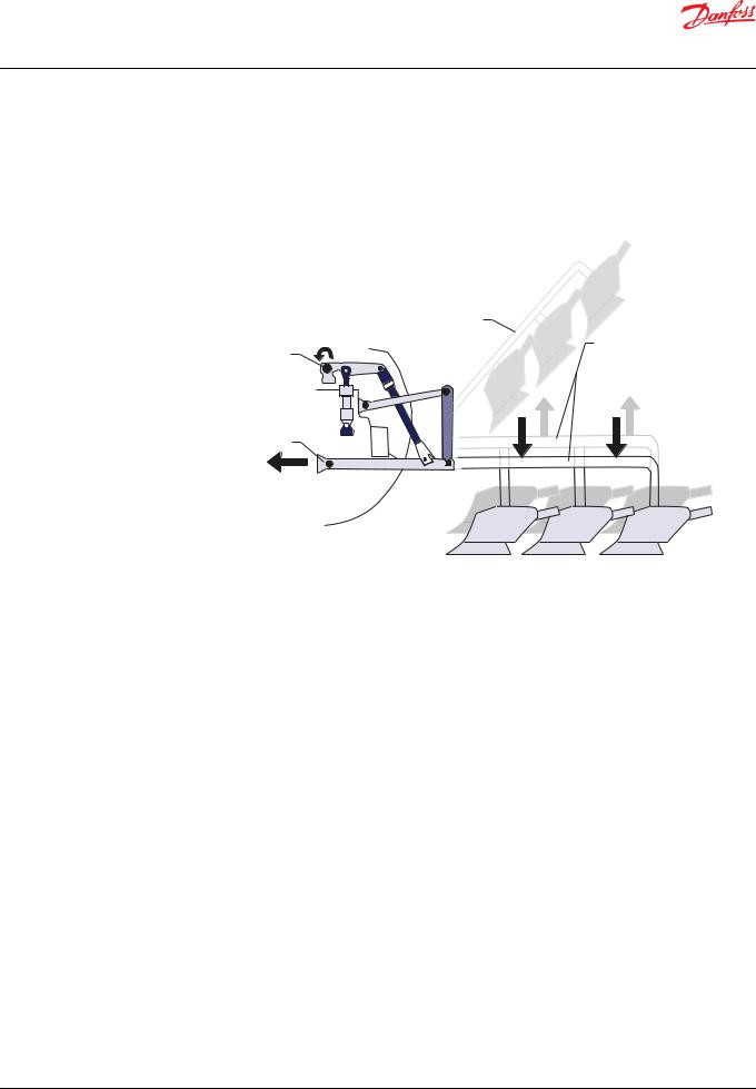
Typical rear hitch
|
Transport mode with |
|
|
active damping |
Work mode: |
Angle sensor |
|
|
|
Lift/ lower around lower |
|
placement |
|
reference setting |
Lift
Draft sensor placement
Lower
Force
© Danfoss | March 2020 |
11036124 | AB152886482484en-000203 | 5 |
Loading...