


Danfoss TUH, TCHE, TGHE, TGHE 10, TGHE 20 Data sheet
...Data Sheet
Hot gas bypass regulator
Types TUH, TCHE and TGHE
Capacity regulator
TUH, TCHE and TGHE capacity regulators adapt compressor capacity to actual evaporator load in applications operating at an evaporating temperature of around 0°C.
TUH, TCHE and TGHE valves are typically used in applications such as:
• Air driers
• Water chillers
Fitted in a bypass between the high and lowpressure sides of the air-drier system, TUH, TCHE and TGHE maintain compressor suction pressure by injecting hot gas/cool gas from the high-pressure side.
TUH has internal pressure equalisation and opens when pressure drops at the valve outlet. TCHE and TGHE have external pressure equalisation and open directly when compressor suction pressure drops.
For all types, the bulb only serves as a reservoir for the charge. However, it is recommended that the bulb be mounted in a location where temperature variation during operation is limited.
AI000086422949en-000401

Hot gas bypass regulator, types TUH, TCHE and TGHE
Features
•Bimetal connections for TUH and TCHE.
◦Straightforward and fast soldering (no wet cloth or refrigeration pliers required)
•Replacement capacities up to 28.9 kW (8.3 TR) for R410A
•Stable regulation
•Tight across the seat
•Compact design.
◦Small dimensions and low weight
•Hermetically tight design
•Stainless steel, hermetically tight solder version
◦high connection strength
◦high corrosion resistance
◦capillary tube joints of high strength and vibration resistance
•Laser-welded, stainless steel diaphragm element
◦optimum function
◦long diaphragm life
◦high pressure resistance
•Adjustable setting
◦accurate setting
◦‚ne tuning possible
•Low p-band
•Low hysteresis
© Danfoss | Climate Solutions | 2021.02 |
AI000086422949en-000401 | 2 |

Hot gas bypass regulator, types TUH, TCHE and TGHE
Functions
Figure 1: TUH, Angleway
2 |
|
3 |
1 |
|
|
4 |
|
Danfoss |
|
68U127 |
|
Figure 2: TCHE, Angleway
2 |
|
3 |
1 |
|
|
4 |
|
Danfoss |
|
68U128 |
|
1 |
Bulb with capillary tube |
|
3 |
Setting spindle for adjustment of opening point/ |
|
|
|
|
minimum suction pressure |
2 |
Diaphragm element |
|
|
|
|
|
|
||
|
|
|
4 |
Fixed ori‚ce |
|
|
|
||
|
|
|
|
|
Figure 3: TGHE 10, Straightway
1 |
|
2 |
|
3 |
|
4 |
|
5 |
|
6 |
|
7 |
|
8 |
Danfoss |
|
67N47.10 |
Figure 4: TGHE 20, TGHE 40 Straightway
1
2
3
4
5
6
7
8
Danfoss 067N8633
1 |
Bulb with capillary tube |
|
5 |
Two-way balance port |
|
|
|
|
|
2 |
Thrust pad |
|
6 |
Valve body |
|
|
|
|
|
3 |
Diaphragm element |
|
7 |
Setting spindle |
|
|
|
|
|
4 |
Push pin seal |
|
8 |
Protective cap |
|
|
|
|
|
The valve is set to start opening at an evaporating temperature of +2°C/+36°F. The setting can be changed by turning the setting spindle. The temperature at which the valve starts opening is increased by turning the spindle anti-clockwise and decreased by turning the spindle clockwise.
Speci‚cally designed for hot gas applications.
All valves react only on to suction pressure variation.
© Danfoss | Climate Solutions | 2021.02 |
AI000086422949en-000401 | 3 |
Hot gas bypass regulator, types TUH, TCHE and TGHE
Applications
NOTE:
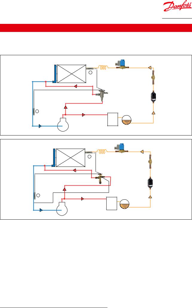
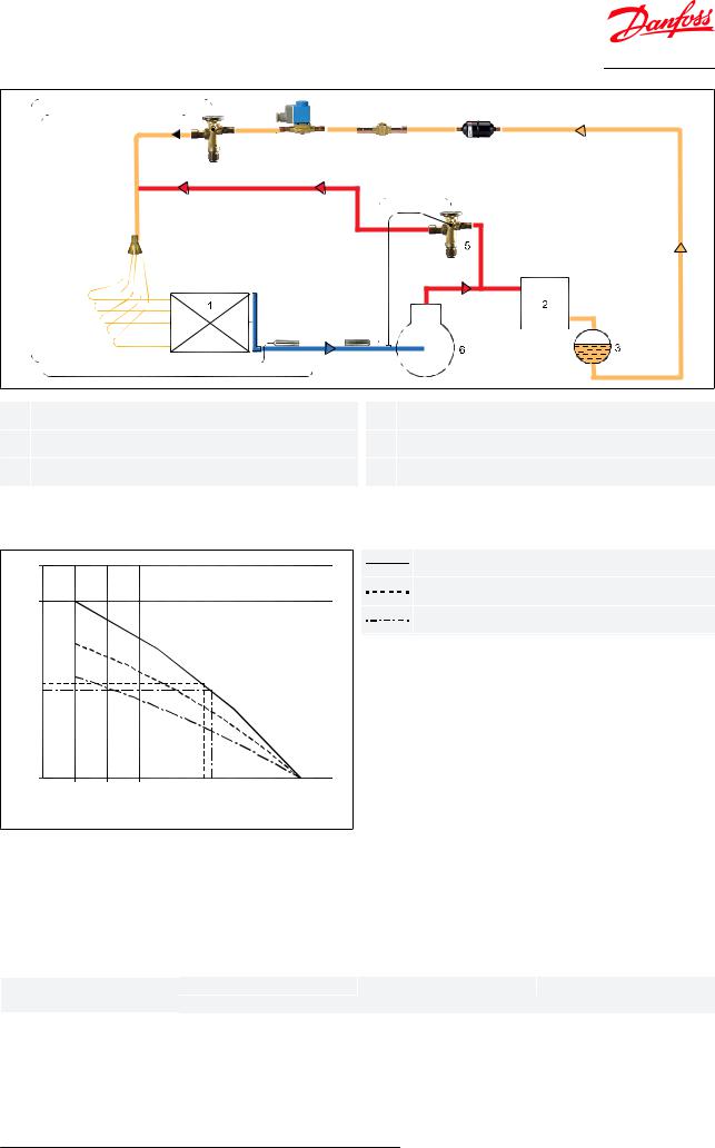
The bulb serves only as a reservoir for the charge, however, it is recommended to mount it in a position where the temperature variation during running conditions is limited (see a and b in the drawings below).
<![endif]>R64-1893.10
<![if ! IE]><![endif]>Danfoss
|
4 |
1 |
|
a |
EVR |
|
SGP |
5 |
|
|
DML |
TCHE / TGHE |
|
b |
3 |
|
|
|
2 |
6 |
|
<![endif]>R64-1894.10
<![if ! IE]><![endif]>Danfoss
|
4 |
1 |
|
a |
EVR |
|
SGP |
5 |
|
|
DML |
TCHE / TGHE |
|
b |
3 |
|
|
|
2 |
6 |
|
1 |
Evaporator |
|
4 |
Solenoid valve |
|
|
|
|
|
2 |
Condenser |
|
5 |
Discharge bypass valve with adjustable setting |
|
|
|
|
|
3 |
Receiver |
|
6 |
Compressor |
|
|
|
|
|
© Danfoss | Climate Solutions | 2021.02 |
AI000086422949en-000401 | 4 |
Hot gas bypass regulator, types TUH, TCHE and TGHE
|
EVR |
SGP |
DML |
|
TGE |
|
|
|
LD |
|
|
|
|
|
TCHE / TGHE |
| <![if ! IE]> <![endif]>Danfoss |
<![if ! IE]> <![endif]>R64-3028.10 |
|
|
1 |
Evaporator |
4 |
Solenoid valve |
2 |
Condenser |
5 |
Discharge bypass valve with adjustable setting |
3 |
Receiver |
6 |
Compressor |
Sizing
Figure 5: Sizing example for R134a
|
6 |
|
|
|
|
|
|
<![if ! IE]> <![endif]>Danfoss R64-1988E |
TCHE 4 |
| <![if ! IE]> <![endif]>[kW] |
5 |
|
|
|
|
|
|
|
TCHE 3 |
|
|
|
|
|
|
|
|
||
|
|
|
|
|
|
|
|
TUH 9 |
|
| <![if ! IE]> <![endif]>capacity |
4 |
|
|
|
|
|
|
|
|
3 |
|
|
|
|
|
|
|
|
|
| <![if ! IE]> <![endif]>Replacement |
2 |
|
|
|
|
|
|
|
|
1 |
|
|
|
|
|
|
|
|
|
|
|
|
|
|
|
|
|
|
|
|
0 |
|
|
|
|
|
|
|
|
|
-6 |
-5 |
-4 -3 -2 |
-1 |
0 |
1 |
2 |
3 |
|
|
|
|
Evaporating temperature [°C] |
|
|
|
|||
Conditions used in calculation: tc = +40°C, Start opening te = +2°C |
|
||||||||
Correction for condensing temperature
The corrected replacement capacity can be obtained by dividing the replacement capacity with the correction factor given below.
Table 1: Correction factor for condensing temperature
Refrigerant |
|
Condensing temperature |
|
|
R134a |
+30°C |
+40°C |
+50°C |
|
0.8 |
1.0 |
1.2 |
||
|
||||
|
|
|
|
Example
Refrigerant: R134
Compressor capacity: 6 kW at +2 /+50 °C
Min. load 50%: 3 kW
Replacement capacity: 6 – 3 = 3 kW
© Danfoss | Climate Solutions | 2021.02 |
AI000086422949en-000401 | 5 |

Hot gas bypass regulator, types TUH, TCHE and TGHE
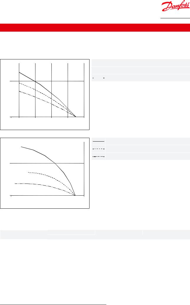
Min. evaporating temperature te: -1.0 °C
Condensing temperature tc: +50 °C
Correction factor (table): 1.2
The corrected replacement capacity thus becomes 3 kW divided by 1.2 = 2.5 kW. The TCHE 4 gives 2.7 kW at -1.0/+40°C (....) and gives 2.5 kW at -0.8/+40°C (- -). Thus the TCHE 4 would be a suitable choice.
© Danfoss | Climate Solutions | 2021.02 |
AI000086422949en-000401 | 6 |

Hot gas bypass regulator, types TUH, TCHE and TGHE
Media
Table 2: Refrigerants features
Features |
Description |
|
|
Standard models |
One standard range per refrigerant |
|
|
Refrigerants |
R134a, R404A/R507, R407C, R22, R410A |
|
|
|
|
|
|
Max. valve body temperature |
120 °C / 248 °F |
|
|
Transient peak |
150 °C / 302 °F |
|
|
|
|
||
|
|
|
|
|
R134a, R22, R407C, R404A |
34 bar / MWP = 500 psig |
|
Max. permissible working pressure (PS) |
R410A |
TCHE |
45.5 bar / 660 psig |
|
TGHE |
49 bar / 710 psig |
|
|
|
||
|
|
|
|
|
R134a, R22, R407C, R404A |
37.5 bar / 540 psig |
|
Max. test pressure |
R410A |
TCHE |
50 bar / 725 psig |
|
TGHE |
54 bar / 755 psig |
|
|
|
||
P-band max. |
0.5 bar / 7.3 psig |
|
|
|
|
||
|
|
|
|
Table 3: Adjustment range for start opening
Valve type |
Orifice sizes |
Refrigerant |
Adjustment range for start opening |
|
||
[°C] |
[°F] |
|||||
|
|
|
||||
|
|
R134a |
-1 - 10 |
+30 |
- +50 |
|
|
|
-6 - +5 |
+21 |
- +41 |
||
|
|
|
||||
TUH |
9 |
R22/R407C |
-4 - +8 |
+25 |
- +46 |
|
|
-1 - +12 |
+30 |
- +54 |
|||
R404A/R507 |
||||||
|
|
|||||
|
|
-42 - -32 |
-44 |
- -26 |
||
|
|
|
||||
|
|
|
|
|
|
|
|
|
R410A |
-1 - +10 |
+30 |
- +50 |
|
|
|
R134a |
-1 - 12 |
+30 |
- +54 |
|
|
|
-5 - +5 |
+23 |
- +41 |
||
|
|
|
||||
|
|
|
|
|
|
|
|
|
R22/R407C |
0 - +8 |
+32 |
- +46 |
|
TCHE |
3 and 4 |
R407C |
-1 - +8 |
+30 |
- +46 |
|
|
|
R404A/R507 |
0 - +6 |
+32 |
- +43 |
|
|
|
R410A |
-1 - +9 |
+30 |
- +48 |
|
|
|
-5 - +5 |
+23 |
- +41 |
||
|
|
|
||||
|
|
|
|
|
|
|
|
|
R134a |
-1 - 12 |
+30 |
- +54 |
|
|
|
R22/R407C |
-1 - +10 |
+30 |
- +50 |
|
TGHE 10 |
10 |
R407C |
-1 - +10 |
+30 |
- +50 |
|
|
|
R404A/R507 |
-1 - +8 |
+30 |
- +46 |
|
|
|
R410A |
-1 - 12 |
+30 |
- +54 |
|
|
|
R134a |
-1 - +13 |
+30 |
- +55 |
|
|
|
R22/R407C |
-1 - +7 |
+30 |
- +45 |
|
TGHE 20 |
20 |
R407C |
-1 - +7 |
+30 |
- +45 |
|
|
|
R404A/R507 |
-1 - +7 |
+30 |
- +45 |
|
|
|
R410A |
-1 - +7 |
+30 |
- +45 |
|
|
|
R134a |
-1 - +16 |
+30 |
- +61 |
|
TGHE 40 |
40 |
R407C |
-1 - +10 |
+30 |
- +50 |
|
R404A/R507 |
-1 - +8 |
+30 |
- +46 |
|||
|
|
|||||
|
|
|
|
|
|
|
|
|
R410A |
-1 - +8 |
+30 |
- +46 |
|
|
|
|
|
|
|
|
© Danfoss | Climate Solutions | 2021.02 |
AI000086422949en-000401 | 7 |
Hot gas bypass regulator, types TUH, TCHE and TGHE
Product speci€cation
Replacement capacity and Mass flow
Replacement capacity - R134a
Figure 6: TUH & TCHE - R134a |
|
|
|
|
|
|||
|
6 |
|
|
|
|
|
|
<![if ! IE]> <![endif]>Danfoss R64-1989E |
| <![if ! IE]> <![endif]>[kW] |
5 |
|
|
|
|
|
|
|
|
|
|
|
|
|
|
|
|
| <![if ! IE]> <![endif]>capacity |
4 |
|
|
|
|
|
|
|
3 |
|
|
|
|
|
|
|
|
| <![if ! IE]> <![endif]>Replacement |
2 |
|
|
|
|
|
|
|
1 |
|
|
|
|
|
|
|
|
|
|
|
|
|
|
|
|
|
|
0 |
|
|
|
|
|
|
|
|
-6 |
-5 |
-4 -3 -2 |
-1 |
0 |
1 |
2 |
3 |
|
|
|
Evaporating temperature [°C] |
|
|
|||
Figure 7: TGHE - R134a |
|
|
|
|
|
|||

 TCHE 4


 TCHE 3


 TUH 9
TUH 9
|
25 |
|
|
|
|
<![if ! IE]> <![endif]>Danfoss R64-1990E |
TGHE 40 |
| <![if ! IE]> <![endif]>[kW] |
20 |
|
|
|
|
|
TGHE 20 |
|
|
|
|
|
TGHE 10 |
||
|
|
|
|
|
|
||
| <![if ! IE]> <![endif]>capacity |
|
|
|
|
|
|
|
15 |
|
|
|
|
|
|
|
|
|
|
|
|
|
|
|
| <![if ! IE]> <![endif]>Replacement |
10 |
|
|
|
|
|
|
5 |
|
|
|
|
|
|
|
|
|
|
|
|
|
|
|
|
0 |
|
|
|
|
|
|
|
-20 |
-15 |
-10 |
-5 |
0 |
3 |
|
|
|
Evaporating temperature [°C] |
|
|
|
||
Conditions used in calculation: tc = +40°C, Start opening te = +2°C |
|||||||
Table 4: Correction factor for condensing temperature
Refrigerant |
|
Condensing temperature |
|
|
R134a |
+30°C |
+40°C |
+50°C |
|
0.8 |
1.0 |
1.2 |
||
|
||||
|
|
|
|
The correction factor can either be multiplied with the valve capacity or the replacement capacity can be divided with the correction factor.
© Danfoss | Climate Solutions | 2021.02 |
AI000086422949en-000401 | 8 |
 Loading...