


Installation Guide
AFP/VFG 2(21) DN 15-250
ENGLISH |
Differential Pressure Controller AFP/VFG 2(21) |
www.danfoss.com |
Page 6 |
|
|
|
|
|
|
|
|
DANSK |
Differenstrykregulator AFP/VFG2 (21) |
www.danfoss.dk |
Side 7 |
|
|
|
|
|
|
|
|
DEUTSCH |
Differenzdruckregler AFP / VFG 2 (21) |
www.danfoss.de |
Seite 8 |
|
|
|
|
|
|
|
|
SVENSKA |
Differenstrycksregulator AFP VFG2 (21) |
www.danfoss.se |
Page 9 |
|
|
|
|
|
|
|
|
FRANCAIS |
Régulateur de pression différentielle AFP / VFG 2 (21) |
www.danfoss.fr |
Page 10 |
|
|
|
|
|
|
|
|
ČESKY |
Regulátoru diferenčního tlaku AFP / VFG 2 (21) |
www.danfoss.cz |
Page 11 |
|
|
|
|
|
|
|
|
SPANISH |
Controlador de presión diferencial AFP / VFG 2 (21) |
www.danfoss.es |
Page 12 |
|
|
|
|
|
|
|
|
SUOMI |
Paine-erosäädin AFP / VFG 2(21) |
www.danfoss.fi |
Sivu 13 |
|
|
|
|
|
|
|
|
POLSKI |
Regulator różnicy ciśnień AFP / VFG 2(21) |
www.danfoss.pl |
Page 14 |
|
|
|
|
|
|
|
|
ROMÂNĂ |
Regulator de presiune diferenţială AFP/VFG 2(21) |
www.danfoss.ro |
Page 15 |
|
|
|
|
|
|
|
|
MAGYAR |
Nyomáskülönbség-szabályozó AFP / VFG 2 (21) |
www.danfoss.hu |
Page 16 |
|
|
|
|
|
|
|
|
РУССКИЙ |
Регулятор перепада давления AFP/VFG 2 (21) |
www.danfoss.ru |
Page 17 |
|
|
|
|
District Energy |
VI.CA.K2.1I |
DEN-SMT/SI |
1 |

Installation Guide |
AFP/VFG 2(21) DN 15-250 |
|
|
||||
|
VFG 2 (21) |
VFG 2 |
|
|
|
|
|
DN 15-125 |
DN 150-250 |
DN 15-125 |
DN 150-250 |
|
|
|
|
tmax = 150 °C |
tmax = 140 °C |
tmax = 200 °C |
tmax = 200 °C |
|
|
||
|
|
|
|||||
|
|
|
|
|
|
|
|
|
AFP |
|
AFP |
|
|
|
|
|
|
|
|
2× |
|
|
|
|
|
|
V1, V2 |
|
|
|
|
|
AF (2×) *) |
AF (2×) *) |
|
|
|
|
|
|
|
|
|
|
|
|
|
|
|
|
|
|
|
|
|
|
|
|
|
|
|
||
|
|
|
|
|
|
|
|
District Energy |
|
|
VI.CA.K2.1I |
|
DEN-SMT/SI |
2 |
|
Installation Guide |
AFP/VFG 2(21) DN 15-250 |
|
|
|
|
|
|
|
|
|
|
|
|
|
|
|
|
|
|
|
|
|
|
|
|
|
|
|
|
|
|
|
|
|
|
|
|
|
|
|
|
|
|
|
|
|
|
|
|
|
|
|
|
|
|
|
|
|
|
|
|
|
G 1/4 |
AF |
|
|
|
|
|
|
|
|
|
|
|
|
|
|
|
|
|
|
|
|
|
|
|
|
|
|
|
|
|
|
|
|
|
|
|
|
|
|
|
|
|
|
|
|
|
|
|
|
|
|
|
|
|
|
|
|
|
|
|
|
|
|
|
|
|
|
|
|
|
|
|
|
|
|
|
|
|
|
|
|
|
|
|
|
|
District Energy |
|
VI.CA.K2.1I |
|
DEN-SMT/SI |
3 |
Installation Guide |
AFP/VFG 2(21) DN 15-250 |
|
|
|
|
|
|
|
|
|
|
|
|
|
|
|
|
|
|
|
|
|
|
|
|
|
|
|
|
|||||||||||||||||||||||
|
|
|
|
|
|
|
|
|
|
|
|
|
|
|
|
|
|
|
|
|
|
|
|
|
|
|
|
|
|
|
|
|
|
|
|
|
|
|
|
|
|
|
|
|
|
|
|
|
|
|
|
|
|
|
|
|
|
|
|
|
|
|
|
|
|
|
|
|
|
|
|
|
|
|
|
|
|
|
|
|
|
|
|
|
|
|
|
|
|
|
|
|
|
|
|
|
|
|
|
|
|
|
|
|
|
|
|
|
|
|
|
|
|
|
|
|
|
|
|
|
|
|
|
|
|
|
|
|
|
|
|
|
|
|
|
|
|
|
|
|
|
|
|
|
|
|
|
|
|
|
|
|
|
|
|
|
|
|
|
|
|
|
|
|
|
|
|
|
|
|
|
|
|
|
|
|
|
|
|
|
|
|
|
|
|
|
|
|
|
|
|
|
|
|
|
|
|
|
|
|
|
|
|
|
|
|
|
|
|
|
|
|
|
|
|
|
|
|
|
|
|
|
|
|
|
|
|
|
|
|
|
|
|
|
|
|
|
|
|
|
|
|
|
|
|
|
|
|
|
|
|
|
|
|
|
|
|
|
|
|
|
|
|
|
|
|
|
|
|
|
|
|
|
|
|
|
|
|
|
|
|
|
|
|
|
|
|
|
|
|
|
|
|
|
|
|
|
|
|
|
|
|
|
|
|
|
|
|
|
|
|
|
|
|
|
|
|
|
|
|
|
|
|
|
|
|
|
|
|
|
|
|
|
|
|
|
|
|
|
|
|
|
|
|
|
|
|
|
|
|
|
|
|
|
|
|
|
|
|
|
|
|
|
|
|
|
|
|
|
|
|
|
|
|
|
|
|
|
|
|
|
|
|
|
|
|
|
|
|
|
|
|
|
|
|
|
|
|
|
|
|
|
|
|
|
|
|
|
|
|
|
|
|
|
|
|
|
|
|
|
|
|
|
|
|
|
|
|
|
|
|
|
|
|
|
|
|
|
|
|
|
|
|
|
|
|
|
|
|
|
|
|
|
|
|
|
|
|
|
|
|
|
|
|
|
|
|
|
|
|
|
|
|
|
|
|
|
|
|
|
|
|
|
|
|
|
|
|
|
|
|
|
|
|
|
|
|
|
|
|
|
|
|
|
|
|
|
|
|
|
|
|
|
|
|
|
|
|
|
|
|
|
|
|
|
|
|
|
|
|
|
|
|
|
|
|
|
|
|
|
|
|
|
|
|
|
|
|
|
|
|
|
|
|
|
|
|
|
|
|
|
|
|
|
|
|
|
|
|
|
|
|
|
|
|
|
|
|
|
|
|
|
|
|
|
|
|
|
|
|
|
|
|
|
|
|
|
|
|
|
|
|
|
|
|
|
|
|
|
|
|
|
|
|
|
|
|
|
|
|
|
|
|
|
|
|
|
|
|
|
|
|
|
|
|
|
|
|
|
|
|
|
|
|
|
|
|
|
|
|
|
|
|
|
|
|
|
|
|
|
|
|
|
|
|
|
|
|
|
|
|
|
|
|
|
|
|
|
|
|
|
|
|
|
|
|
|
|
|
|
|
|
|
|
|
|
|
|
|
|
|
|
|
|
|
|
|
|
|
|
|
|
|
|
|
|
|
|
|
|
|
|
|
|
|
|
|
|
|
|
|
|
|
|

|
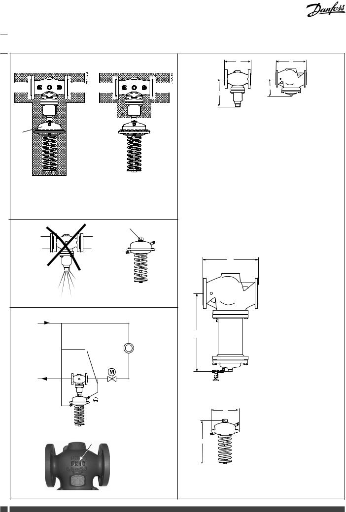
B1
H
L |
L |
|
B |
B
VFG 2(21)
DN |
L |
|
B |
Weight |
|
|
|
|
|
|
mm |
(kg) |
||
|
|
|||
|
|
|
|
|
15 |
130 |
|
212 |
7 |
|
|
|
|
|
20 |
150 |
|
238 |
9 |
|
|
|
|
|
25 |
160 |
|
238 |
10 |
|
|
|
|
|
32 |
180 |
|
240 |
13 |
|
|
|
|
|
40 |
200 |
|
240 |
17 |
|
|
|
|
|
50 |
230 |
|
275 |
22 |
|
|
|
|
|
65 |
290 |
|
275 |
33 |
|
|
|
|
|
80 |
310 |
|
380 |
41 |
|
|
|
|
|
100 |
350 |
|
380 |
60 |
|
|
|
|
|
125 |
400 |
|
380 |
79 |
|
|
|
|
|
150 |
480 |
|
326 |
85 |
|
|
|
|
|
200 |
600 |
|
354 |
145 |
|
|
|
|
|
250 |
730 |
|
404 |
228 |
|
|
|
|
|
L
VFG 2 tmax = 200 °C
|
|
|
|
|
|
|
|
|
|
|
|
DN |
B1 |
|
L |
Weight |
|
|
|
|
|
|
|
|
|
|
|
|
|
mm |
(kg) |
||
|
|
|
|
|
|
|
|
|
|
|
|
|
|
|||
|
|
|
|
|
|
|
|
|
|
|
|
150 |
630 |
|
480 |
140 |
|
|
|
|
|
|
|
|
|
|
|
|
|
|
|
|
|
|
|
|
|
|
|
|
|
|
|
|
|
200 |
855 |
|
600 |
210 |
|
|
|
|
|
|
|
|
|
|
|
|
|
||||
|
|
|
|
|
|
|
|
|
|
|
|
250 |
1205 |
|
730 |
300 |
|
|
|
|
|
|
|
|
|
||||||||
|
|
|
|
|
|
|
|
|
|
|
|
|
|
|
|
|
A
|
|
|
|
|
|
|
|
|
|
AFP |
A |
|
H |
Weight |
|
|
|
|
|
|
|
|
|
||||||
|
|
|
|
|
|
|
|
|
|
|
||||
|
|
|
|
|
|
|
|
|
|
(mm2) |
mm |
|
(kg) |
|
|
|
|
|
|
|
|
|
|
|
|
||||
|
|
|
|
|
|
|
|
|
|
80 |
172 |
|
430 |
7,5 |
|
|
|
|
|
|
|
|
|
|
|
||||
|
|
|
|
|
|
|
|
|
|
250 |
263 |
|
470 |
13 |
|
|
|
|
|
|
|
|
|
|
630 |
380 |
|
580 |
28 |
4 DEN-SMT/SI |
VI.CA.K2.1I |
District Energy |
Installation Guide |
AFP/VFG 2(21) DN 15-250 |
|
|
|
|
|
|
|
|
|
|
|
|
Δps = 0,5-3 bar
p
0 50% Vmax
|
|
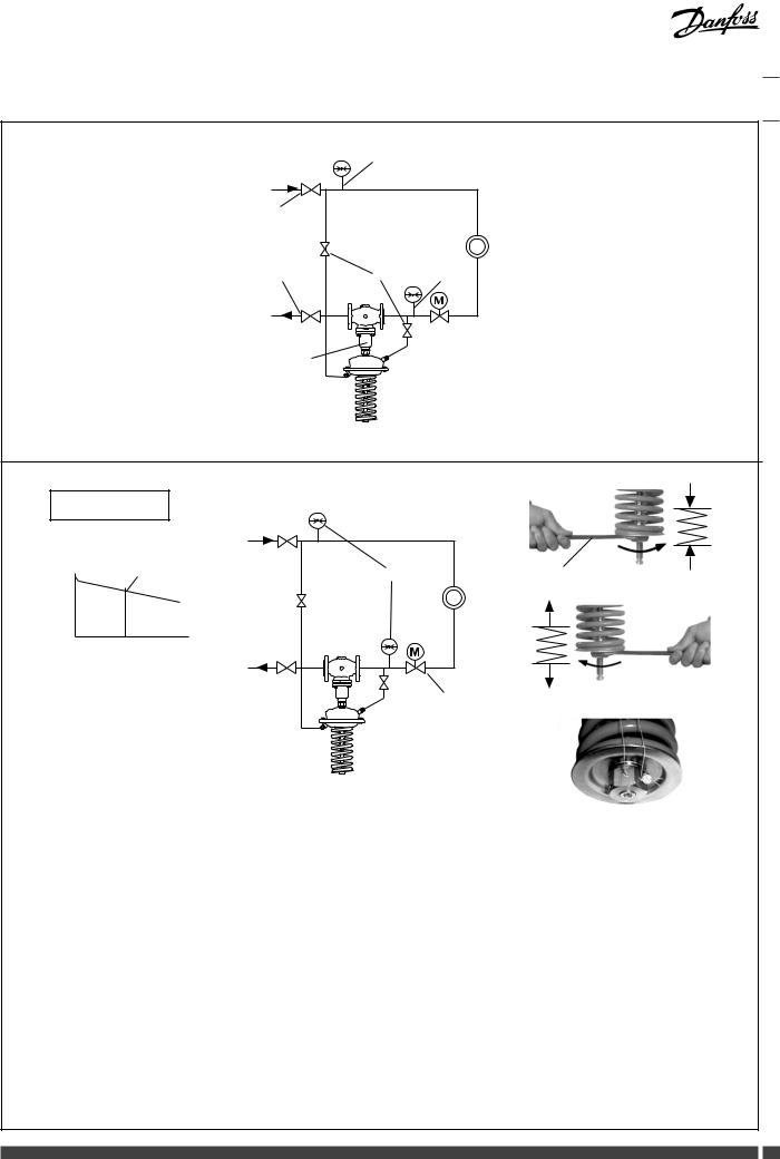
36 mm

District Energy |
VI.CA.K2.1I |
DEN-SMT/SI |
5 |
Installation Guide |
AFP/VFG 2(21) DN 15-250 |
|
|
LAENGLISHUAGE
Safety Notes
Prior to assembly and commissioning to avoid injury of persons and damages of the devices, it is absolutely necessary to
carefully read and observe these instructions.
Necessary assembly, start-up, and maintenance work must be performed only by qualified, trained and authorized personnel.
Prior to assembly and maintenance work on the controller, the system must be:
-depressurized,
-cooled down,
-emptied and
-cleaned.
Please comply with the instructions of the system manufacturer or system operator.
Disposal instructions
This product should be dismantled and its components sorted, if possible, in various groups before recycling or
disposal.
Always follow the local disposal regulations.
Definition of Application
The controller is used for differential pressure control of water and water glycol mixtures for heating, district heating and cooling systems.
The technical data on the rating plates determine the use.
Scope of Delivery
*) Impulse tube AF, accessory
Assembly
Admissible Installation Positions
DN 15-80 :
medium temperatures up to 120 °C: Can be installed in any position.
DN 100-250 and DN 15-80 : medium temperatures > 120 °C.
Installation permitted only in horizontal pipelines with the actuator oriented downwards.
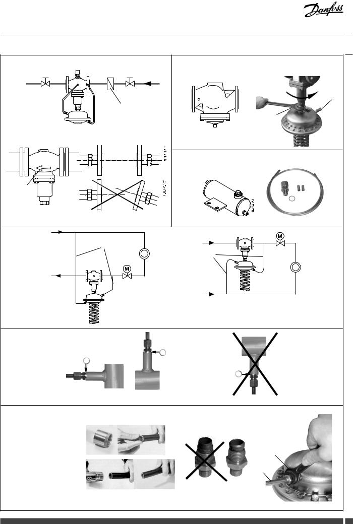
Installation Location and Installation Scheme
Return mounting Flow mounting
Valve Installation
1.Install strainer before the controller.
2.Rinse system prior to installing the valve.
3.Observe flow direction on valve body.
Flanges in the pipeline must be in parallel position and sealing surfaces must be clean and without any damage.
4.Install valve.
5.Tighten screws crosswise in 3 steps up to the max. torque.
Valve Actuator Installation
Valves DN 150-250
The actuator stem must be screwed into the valve stem.
Observe the Installation Instructions for the valves DN 150-250.
Valves DN 15-125
1.Place actuator at the valve.
2.Align actuator, observe position of impulse tube connection to the valve
3.Tighten union nut Torque 100 Nm
Impulse Tube mounting
When installing seal pots , please observe the Installation Instructions for the seal pots.
• Which impulse tubes to use?
The impulse tube set AF (2×) can be used: Order No.: 003G1391
or use the following pipes:
Stainless steel |
Ø 10×0,8 |
DIN 17458, |
|
DIN 2391 |
|||
|
|
||
Steel |
Ø 10×1 |
DIN 2391 |
|
Copper |
Ø 10×1 |
DIN 1754 |
• Connection of impulse tubes in the system
Installation in return flow Installation in supply flow
• Connection to the pipeline
No connection downwards , could be chocked by dirt.
• Impulse Tube Installation (Copper)
1. Cut pipe into rectangular sections and deburr.
2. Insert sleeves on both sides.
3. Verify the correct position of the cutting ring .
4. Press impulse tube into the threaded joint up to its stop.
5. Tighten union nut . Torque 40 Nm
Insulation
For medium temperatures up to 100 °C the pressure actuator may be insulated .
Dimensions
Flanges: connection dimensions acc. to DIN 2501, seal form C
Dismounting
Danger
Danger of injury by hot water
Valve without actuator is open , Seal is in the actuator.
Prior to dismounting depressurize system!
Carry out dismounting in reverse order to mounting.
Leak and Pressure Test
Pressure must be constantly increased at the +/- connection . Never increase − pressure above + pressure.
Observe max. permitted pressure, see below. Non-compliance may cause damages at the actuator or valve.
Max. test pressure [bar] with connected impulse tubes
AFP cm2 |
80 |
250 |
630 |
bar |
25 |
25 |
16 |
In case of higher test pressures, remove impulse tubes at the pipelines .
Close connections with plugs G ¼ ISO 228.
Observe nominal pressure of the valve.
Max. test pressure is 1,5 × PN
Filling the System, Start-up
The return flow pressure must not exceed the supply flow pressure .
Non-compliance may cause damages at the controller .
1.Open shut-off devices that are possibly available at the impulse tubes.
2.Slowly open valves in the system.
3.Slowly open shut-off devices in the supply flow.
4.Slowly open shut-off devices in the return flow.
Putting out of Operation
1.Slowly close shut-off devices in the supply flow.
2.Slowly close shut-off devices in the return flow.
Differential Pressure Setting
Set-point range see rating plate
1.Start-up of system, see section .
2.Set flow rate on a motorised valve by which the differential pressure is controlled, to about 50 %
3.Adjustment
•Observe pressure indicators .
•Turning to the right increases the setpoint (stressing the spring)
•Turning to the left reduces the set-point (unstressing the spring)
4.The set-point adjuster may be sealed.
6 DEN-SMT/SI |
VI.CA.K2.1I |
District Energy |
 Loading...