


 Loading...
Danfoss Series 51 - HZ, Series 51 - HA, Series 51 - HB, Series 51 - HE, Series 51 - HS Service guide
...MAKING MODERN LIVING POSSIBLE
Service Manual
Series 51 - HZ, HA, HB, HE, HS, H1, H2, K1, K2, HP, HC, J1, J2, J3, J4, JA Hydraulic Proportional Controls
powersolutions.danfoss.com

Service Manual |
Series 51 Hydraulic Proportional Controls Service Manual |
|
|
Revision history |
Table of revisions |
|
|
|
|
|
|
|
Date |
Changed |
Rev |
|
|
|
|
|
July 2014 |
Danfoss layout |
BA |
|
|
|
|
|
November 2010 |
new last page |
AC |
|
|
|
|
|
February 2010 |
Fix Osaka address |
AB |
|
|
|
|
|
July 2009 |
First edition |
AA |
|
|
|
|
2 |
11009446 • Rev BA • July 2014 |

Service Manual |
Series 51 Hydraulic Proportional Controls Service Manual |
|
Contents |
|
|
Introduction |
|
|
|
Safety Precautions............................................................................................................................................................................ |
5 |
|
Unintended Machine Movement.......................................................................................................................................... |
5 |
|
Flammable Cleaning Solvents................................................................................................................................................ |
5 |
|
Fluid Under Pressure.................................................................................................................................................................. |
5 |
|
Personal Safety............................................................................................................................................................................. |
5 |
|
Hazardous Material..................................................................................................................................................................... |
5 |
|
Symbols used in Danfoss literature............................................................................................................................................ |
6 |
|
Overview.............................................................................................................................................................................................. |
6 |
|
General Instructions........................................................................................................................................................................ |
7 |
|
Keep it Clean................................................................................................................................................................................. |
7 |
|
Inspect for System Contamination....................................................................................................................................... |
7 |
|
Replace the O-rings and Gaskets........................................................................................................................................... |
7 |
|
Lubricate all Moving Parts........................................................................................................................................................ |
7 |
|
Torque Procedure....................................................................................................................................................................... |
7 |
|
General Description......................................................................................................................................................................... |
7 |
|
Overview........................................................................................................................................................................................ |
7 |
|
Threshold and Ramp Springs.................................................................................................................................................. |
7 |
|
Multiblock...................................................................................................................................................................................... |
8 |
|
Pressure Compensator OverRide (PCOR) Function........................................................................................................ |
8 |
|
Brake Pressure Defeat (BPD) Option.................................................................................................................................... |
9 |
Pressure measurements |
|
|
|
Port locations and Gauge Installation.................................................................................................................................... |
10 |
Adjustments |
|
|
|
Threshold Setting........................................................................................................................................................................... |
11 |
|
Checking Threshold Setting................................................................................................................................................. |
11 |
|
Adjusting Threshold Setting................................................................................................................................................. |
11 |
|
Pressure Compensator OverRide (PCOR) Setting............................................................................................................... |
12 |
|
PCOR Adjustment..................................................................................................................................................................... |
12 |
|
Checking PCOR Setting on a Test Stand.......................................................................................................................... |
13 |
|
Adjusting the PCOR Setting.................................................................................................................................................. |
13 |
PCOR |
|
|
|
Optional PCOR Housing............................................................................................................................................................... |
14 |
|
Disassembly................................................................................................................................................................................ |
14 |
|
Inspection.................................................................................................................................................................................... |
14 |
|
Assembly...................................................................................................................................................................................... |
14 |
Multifunction block |
|
|
|
Optional Multifunction block ................................................................................................................................................... |
16 |
|
Disassembly................................................................................................................................................................................ |
16 |
|
Inspection.................................................................................................................................................................................... |
17 |
|
Assembly...................................................................................................................................................................................... |
17 |
HZ, HA, HB, HE Controls |
|
|
|
Operation.......................................................................................................................................................................................... |
18 |
|
Functional Description........................................................................................................................................................... |
18 |
|
HZ Control................................................................................................................................................................................... |
18 |
|
HA and HB Controls................................................................................................................................................................. |
18 |
|
HE Control................................................................................................................................................................................... |
18 |
|
Repair.................................................................................................................................................................................................. |
19 |
|
Disassembly................................................................................................................................................................................ |
19 |
|
Inspection.................................................................................................................................................................................... |
20 |
|
Assembly...................................................................................................................................................................................... |
20 |
HS Control |
|
|
|
Operation.......................................................................................................................................................................................... |
21 |
|
Functional Description........................................................................................................................................................... |
21 |
|
Repair.................................................................................................................................................................................................. |
21 |
|
Disassembly................................................................................................................................................................................ |
21 |
11009446 • Rev BA • July 2014 |
3 |

Service Manual |
Series 51 Hydraulic Proportional Controls Service Manual |
|
|
Contents |
|
Inspection.................................................................................................................................................................................... |
22 |
Assembly...................................................................................................................................................................................... |
22 |
H1, H2, K1, K2 Controls |
|
Operation.......................................................................................................................................................................................... |
23 |
Functional Description........................................................................................................................................................... |
23 |
Solenoid Valve........................................................................................................................................................................... |
23 |
Repair.................................................................................................................................................................................................. |
23 |
Removing Solenoid Valve...................................................................................................................................................... |
24 |
Disassembly................................................................................................................................................................................ |
24 |
Inspection.................................................................................................................................................................................... |
24 |
Assembly...................................................................................................................................................................................... |
24 |
Installing Solenoid.................................................................................................................................................................... |
24 |
HP Controls |
|
Operation.......................................................................................................................................................................................... |
25 |
Functional Description........................................................................................................................................................... |
25 |
HP Control................................................................................................................................................................................... |
25 |
Shuttle Valve............................................................................................................................................................................... |
25 |
Connecting Pin.......................................................................................................................................................................... |
25 |
Repair.................................................................................................................................................................................................. |
26 |
Disassembly................................................................................................................................................................................ |
26 |
Inspection.................................................................................................................................................................................... |
27 |
Assembly...................................................................................................................................................................................... |
27 |
HC Controls |
|
Operation.......................................................................................................................................................................................... |
28 |
Functional Description........................................................................................................................................................... |
28 |
Check Valve................................................................................................................................................................................. |
28 |
Shuttle Valve............................................................................................................................................................................... |
28 |
Connecting Pin.......................................................................................................................................................................... |
28 |
Repair.................................................................................................................................................................................................. |
28 |
Diassembly.................................................................................................................................................................................. |
28 |
Inspection.................................................................................................................................................................................... |
29 |
Assembly...................................................................................................................................................................................... |
31 |
J1, J2, J3, J4 Controls |
|
Operation.......................................................................................................................................................................................... |
32 |
Functional Description........................................................................................................................................................... |
32 |
Solenoid Valve........................................................................................................................................................................... |
32 |
Repair.................................................................................................................................................................................................. |
33 |
Removing the Solenoid Valve.............................................................................................................................................. |
33 |
Disassembly................................................................................................................................................................................ |
34 |
Inspection.................................................................................................................................................................................... |
34 |
Assembly...................................................................................................................................................................................... |
35 |
Installing the Solenoid Valve................................................................................................................................................ |
35 |
JA Control |
|
Operation.......................................................................................................................................................................................... |
36 |
Functional Description........................................................................................................................................................... |
36 |
Signal Pressure........................................................................................................................................................................... |
36 |
Repair.................................................................................................................................................................................................. |
36 |
Disassembly................................................................................................................................................................................ |
36 |
Inspection.................................................................................................................................................................................... |
38 |
Assembly...................................................................................................................................................................................... |
38 |
4 |
11009446 • Rev BA • July 2014 |

Service Manual |
Series 51 Hydraulic Proportional Controls Service Manual |
|
|
Introduction
Safety Precautions
Always consider safety precautions before beginning a service procedure. Protect yourself and others from injury. Take the following general precautions whenever servicing a hydraulic system.
Unintended Machine Movement
W Warning
Unintended movement of the machine or mechanism may cause injury to the technician or bystanders. To protect against unintended movement, secure the machine or disable/disconnect the mechanism while servicing.
Flammable Cleaning Solvents
W Warning
Some cleaning solvents are flammable. To avoid possible fire, do not use cleaning solvents in an area where a source of ignition may be present.
Fluid Under Pressure
W Warning
Escaping hydraulic fluid under pressure can have sufficient force to penetrate your skin causing serious injury and/or infection. This fluid may also be hot enough to cause burns. Use caution when dealing with hydraulic fluid under pressure. Relieve pressure in the system before removing hoses, fittings, gauges, or components. Never use your hand or any other body part to check for leaks in a pressurized line. Seek medical attention immediately if you are cut by hydraulic fluid.
Personal Safety
W Warning
Protect yourself from injury. Use proper safety equipment, including safety glasses, at all times.
Hazardous Material
W Warning
Hydraulic fluid contains hazardous material. Avoid prolonged contact with hydraulic fluid. Always dispose of used hydraulic fluid according to state, and federal environmental regulations.
11009446 • Rev BA • July 2014 |
5 |
Service Manual |
Series 51 Hydraulic Proportional Controls Service Manual |
|
|
Introduction
Symbols used in Danfoss literature
WARNING may result in injury |
Tip, helpful suggestion |
CAUTION may result in damage to product or |
Lubricate with hydraulic fluid |
property |
|
Reusable part |
Apply grease / petroleum jelly |
Non-reusable part, use a new part |
Apply locking compound |
Non-removable item |
Inspect for wear or damage |
Option - either part may exist |
Clean area or part |
Superseded - parts are not interchangeable |
Be careful not to scratch or damage |
Measurement required |
Note correct orientation |
Flatness specification |
Mark orientation for reinstallation |
Parallelism specification |
Torque specification |
External hex head |
Press in - press fit |
Internal hex head |
Pull out with tool – press fit |
Torx head |
Cover splines with installation sleeve |
O-ring boss port |
Pressure measurement/gauge location or |
|
specification |
The symbols above appear in the illustrations and text of this manual. They are intended to communicate helpful information at the point where it is most useful to the reader. In most instances, the appearance of the symbol itself denotes its meaning. The legend above defines each symbol and explains its purpose.
Overview
This manual includes information for the installation, maintenance, and minor repair of Series 51 hydraulic proportional controls. It includes a description of the unit and its individual components, and minor repair procedures.
Performing minor repairs may require removal of the unit from the vehicle/machine. Thoroughly clean the unit before beginning maintenance, or repair activities. Since dirt and contamination are the greatest enemies of any type of hydraulic equipment, follow cleanliness requirements strictly. This is especially important when changing the system filter and when removing hoses or plumbing.
A worldwide network of Danfoss Global Service Partners is available for major repairs. Danfoss Global Service Partners are trained by the factory and certified on a regular basis. You can locate your nearest Global Service Partner using the distributor locator at www.powersolutions.danfoss.com. Click on the
Sales and Service link.
6 |
11009446 • Rev BA • July 2014 |

Service Manual |
Series 51 Hydraulic Proportional Controls Service Manual |
|
|
Introduction
General Instructions
Keep it Clean
You can complete many repairs or adjustments without removing the unit from the machine, if the unit is accessible and you can thoroughly clean it before beginning any procedures.
Cleanliness is a primary means of assuring satisfactory motor life on either new or repaired units. Clean the outside of the motor thoroughly before disassembly. Take care to avoid contamination of the system ports. Cleaning parts with a clean solvent wash and air drying is usually adequate.
As with any precision equipment, keep all parts free of foreign materials and chemicals. Protect all exposed sealing surfaces and open cavities from damage and foreign material. Cap all hoses after removal, and plug all open ports. Cover any unattended parts with a protective layer of plastic.
Inspect for System Contamination
Inspect the motor for signs of system contamination. If you find contamination, fully disassemble, clean and inspect all components of the motor.
Replace the O-rings and Gaskets
Replace all O-rings and gaskets. Discard them only after you make certain that you have the correct replacement parts. Lightly lubricate all O-rings with clean petroleum jelly before assembly.
Lubricate all Moving Parts
During reassembly, coat all moving parts with a film of clean hydraulic oil. This helps lubricate the surfaces during start-up.
For fluid quality requirements, refer to 520L0463 Hydraulic Fluids and Lubricants, Technical Information.
Torque Procedure
During reassembly, cross torque all retaining screws to the given value. Do not overtorque.
General Description
Overview
Hydraulic proportional controls infinitely vary the motor displacement between maximum and minimum by feeding a variable hydraulic signal pressure to the end of the 4-way valve directly, or to a piston that moves the 4-way valve As signal-pressure shifts the 4-way valve, it ports pressure to the ends of the servo piston, changing motor displacement. A threshold spring and a ramp spring act on the opposite end of the 4-way valve.
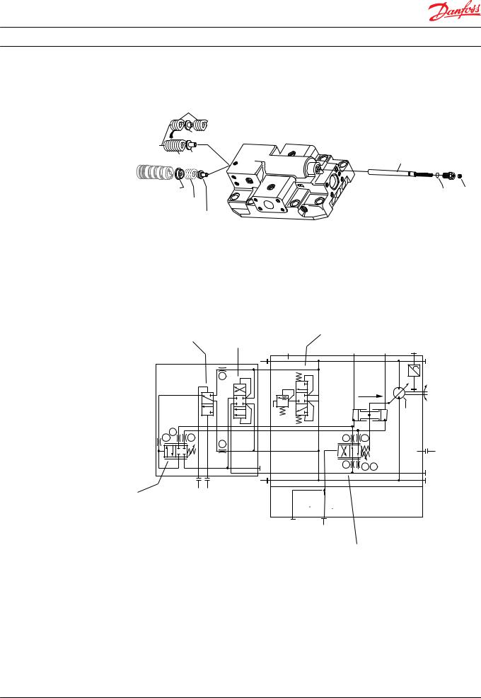
Threshold and Ramp Springs
The threshold adjustment screw varies the threshold spring force required to move the 4-way valve and start the change in displacement. The ramp spring(s)—2 used in 160cc and 250cc motors, and one used in the 80 cc and 110cc motors—increase the force on the 4-way valve as the servo piston moves toward minimum displacement. This provides a motor displacement proportional to the input signal pressure.
The control operating threshold (the signal pressure when the motor starts to shift) is adjustable. Adjust it using the adjusting screw in the end cap.
Changing ramp spring force requires replacing the springs. There are several spring rates available.
Optional orifices may be installed at several locations to regulate shift speed. Refer to the Model Code for your motor for details.
11009446 • Rev BA • July 2014 |
7 |
Service Manual |
Series 51 Hydraulic Proportional Controls Service Manual |
Introduction
Threshold and Ramp Springs
|
S10* |
|
Ramp spring(s) |
S10 |
|
|
||
|
S10* |
S20 |
|
|
|
Spring seat |
|
|
Threshold spring |
||
|
Spring seat J30 |
|
P106 438E
Threshold adjustment screw
J50 locknut
Multiblock
Some hydraulic proportional controls are used in conjunction with the multiblock. The multiblock is a manifold with a shuttle-valve that routes high loop (system pressure) from port A or port B to the 4-way valve to serve as servo supply and to the PCOR function. The shuttle valve also routes the low pressure side of the loop to the PCOR function.
Multifunction Schematic
BPD Spool |
|
|
Loop Flush |
|
|
|
|
|
Shuttle |
|
|
|
|
||
|
|
|
|
|
|
|
|
|
|
|
L2 |
M4 |
|
M3 |
N |
|
|
|
A |
|
|
|
M1 |
|
|
|
|
|
|
|
|
|
|
T4 |
|
max. |
n |
||
|
|
|
|
||||
|
|
|
|
disp. |
|
||
|
U7 |
|
|
|
|
|
|
T5 |
U6 |
|
|
T2 |
T3 |
|
|
|
|
T6 |
|
|
|
|
|
|
|
|
|
|
|
|
L1 |
|
|
|
|
T1 |
T7 |
T8 |
|
|
|
|
|
|
M5 |
||
|
|
|
|
|
|
|
|
|
XA |
XB |
B |
|
|
|
M2 |
|
|
|
|
|
|||
PCOR Valve |
Multiblock |
|
|
|
|
|
|
|
|
|
|
|
|
||
|
|
|
M7 |
X1 |
|
Control |
|
|
|
|
|
4-Way Valve |
P106 417E |
||
|
|
|
|
|
|
|
|
Pressure Compensator OverRide (PCOR) Function
The Pressure Compensator OverRide (PCOR) function allows the motor to match its displacement to the system load. The PCOR overrides the control command allowing the motor to increase displacement when system pressure reaches a set level due to load. This permits the motor to regulate system pressure by modulating the displacement of the rotating group. As displacement increases, available torque increases. Output speed decreases and system pressure remains nearly constant at the PCOR setting.
The PCOR setting is adjustable from 110 to 370 bar [1595 to 5365 psi]. Optional orifices at locations T4, T5, T6, U6, and U7 regulate the PCOR operation speed.
8 |
11009446 • Rev BA • July 2014 |
Service Manual |
Series 51 Hydraulic Proportional Controls Service Manual |
|
|
Introduction
Optional Orifices: T4, T5, T6, U6, U7
T4
 T5
T5
 T6
T6


 U7
U7
U6


P106 415E
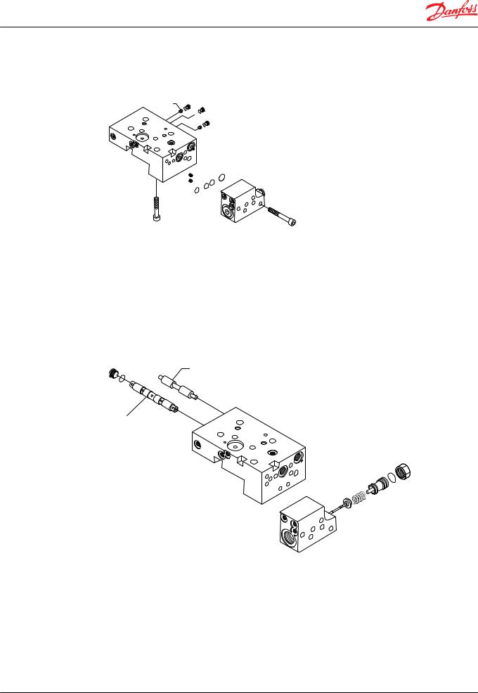
Brake Pressure Defeat (BPD) Option
The PCOR function can be equipped with an optional brake pressure defeat (BPD) option that defeats the PCOR operation during dynamic braking. A shuttle spool ahead of the PCOR valve directs only acceleration system pressure to the PCOR. During deceleration the dynamic braking pressure is blocked from the PCOR limiting rapid deceleration, uncontrolled pressures or engine over-speeding while the vehicle/machine is slowing down. An external hydraulic signal pressure fed to ports XA or XB are required to operate the BPD spool. PCOR operation on one system pressure side is also an option.
BPD Option
Brake defeat spool
Shuttle valve
 PCOR adjuster
 PCOR spool
P106 431E
11009446 • Rev BA • July 2014 |
9 |

Service Manual |
Series 51 Hydraulic Proportional Controls Service Manual |
|
|
Pressure measurements
Port locations and Gauge Installation
The following table and drawings show the port locations and gauge sizes needed. When testing system pressures, calibrate pressure gauges frequently to ensure accuracy. Use snubbers to protect gauges.
Port Information
Port identifier |
Port size |
Wrench size |
Reading |
Gauge size, bar [psi] |
|
|
|
|
|
L1, L2 |
1 1/16-12 UNF |
9/16 internal hex |
Case drain |
10 bar [100 psi] |
|
|
|
|
|
M1, M2 |
9/16-18 UNF |
1/4 internal hex |
System pressure |
600 bar [10,000 psi] |
|
|
|
|
|
M3, M4, M5 |
9/16-18 UNF |
1/4 internal hex |
Servo pressure |
50 bar [1000 psi] |
|
|
|
|
|
X1, M7 |
9/16-18 UNF |
1/4 internal hex |
Control pressure |
50 bar [1000 psi] |
|
|
|
|
|
Port Locations
Radial ported motor
L1 
L2

M3 |
M4 |
|
|
|
M4 |
|
Threshold |
|
adjustment |
|
M3 |


 A
A 
M1
M5
M2
M1
M5
M7
X1
M7 |
| <![if ! IE]> <![endif]>X1 |
Axial ported motor |
M1+M2 |
M3
A 
M4B
M5

 System port B System port A
P106 434E
10 |
11009446 • Rev BA • July 2014 |
Service Manual |
Series 51 Hydraulic Proportional Controls Service Manual |
|
|
Adjustments
Threshold Setting
Checking Threshold Setting
1.Install a 50 bar [600 psi] gauge at port M3 to read minimum servo pressure.
2.Install a 50 bar [600 psi] gauge at port M4 to read maximum servo pressure.
3.Install meter to read signal current.
4.Increase the signal current to the proper setting.
The pressure at port M3 should rise to about 100 psi [6.89 bar] higher than the pressure at port M4. This causes the servo piston to move toward minimum position. Signal current at this point is the threshold setting.
On a test stand, increase signal current until the flow from the motor begins to decrease. The signal current at this point is the threshold setting.
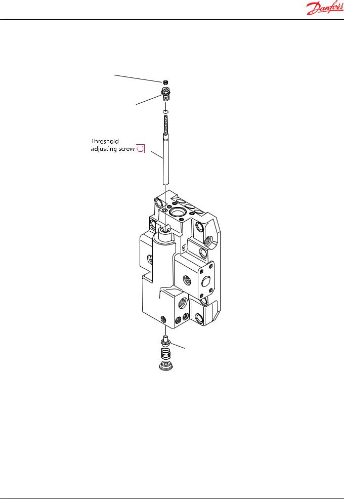
Adjusting Threshold Setting
1.Using a 10 mm wrench, loosen the locknut on the adjustment screw.
2.Using a 3 mm internal hex wrench turn the adjusting screw:
•Clockwise (cw) to increase the setting
•Counterclockwise (ccw) to decrease the setting.
3.While holding the position of the adjustment screw:
•tighten the locknut
•using a 10 mm wrench torque the locknut to 9 N•m [6.6 lbf•ft].
11009446 • Rev BA • July 2014 |
11 |
Service Manual |
Series 51 Hydraulic Proportional Controls Service Manual |
|
|
Adjustments
Locknut and Threshold
Locknut
 10 mm
10 mm
 9 Nm [6.6 lbf•ft]
Adjusting screw
Spring seat
P101 911
Pressure Compensator OverRide (PCOR) Setting
PCOR Adjustment
In order to measure and adjust the start pressure setting for the PCOR function:
1.Install a 600 bar [10000 psi] gauge at port M1 or M2 or M5 to read high system pressure.
2.Install a 600 bar [10000 psi] gauge at port M3 to read minimum servo pressure.
3.Lock the motor shaft from moving by:
•Applying the park brake, apply an extreme load, or
•Position the machine against an immovable object, or
•Other means to hold the machine.
4.Start the prime mover. Operate at medium RPM.
12 |
11009446 • Rev BA • July 2014 |
Loading...