


MAKING MODERN LIVING POSSIBLE
TS715Si
Electronic Single Channel Timeswitch
with Service Interval Timer
Danfoss Heating
Installation Guide

GB
For a large print version of these instructions please call Marketing on 0845 121 7400.
®
Certification Mark
Danfoss can accept no responsibility for possible errors in catalogues, brochures, and other printed material. All trademarks in this material are property of the respective companies. Danfoss and the Danfoss logotype are trademarks of Danfoss A/S. All rights reserved.
2 |
TS715SI |
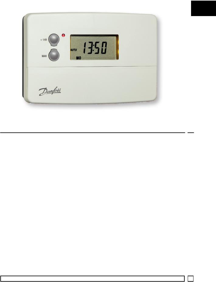
TS715Si
Electronic Single Channel Timeswitch with Service Interval Timer
Index
1.0 |
Installation Overview.............................................................................. |
4 |
|
2.0 |
Product Specification.............................................................................. |
4 |
|
3.0 |
Installation |
|
|
|
3.1 |
Wiring..................................................................................................... |
5 |
|
3.2 |
DIL Switch Settings ........................................................................... |
6 |
4.0 |
Advanced Programming Options ..................................................... |
6 |
|
5.0 |
Copy Functions Explained .................................................................... |
7 |
|
6.0 |
Service Interval Timer............................................................................. |
9 |
|
7.0 |
Wiring Conversions ......................................................................... |
10-13 |
|
Danfoss Heating |
|
3 |

1.0 Installation Overview
Please Note:
This product should only be installed by a qualified electrician or competent heating installer and should be in accordance with the
GB current edition of the IEEE wiring regulations.
2.0 Product Specification
Specification |
230V model |
|
24V model |
|
|
|
|
|
230 Vac, |
|
24 Vac, |
Power supply |
±15%, |
|
±15%, |
|
50/60 Hz |
|
50/60 Hz |
|
|
|
|
Switching action |
1 x SPDT voltage free, Type 1B |
||
|
|
||
Switch rating |
24-230 Vac, 3(1)A |
||
|
|
||
Battery back-up |
24 hours minimum |
||
|
|
||
Setting/Running Accuracy |
± 1 minute |
||
|
|
||
Dimensions, mm (W, H, D) |
135 x 88 x 32 |
||
|
|
||
Design standard |
EN 60730-2-7 |
||
|
|
||
Control Pollution Situation |
Degree 2 |
||
|
|
|
|
Rated Impulse Voltage |
|
2.5 kV |
|
|
|
|
|
Ball Pressure Test |
|
75°C |
|
|
|
|
|
3.0 Installation
•Remove wallplate from unit by unscrewing the two screws on the bottom edge of the unit.
•From the top left hand corner of the wallplate, there must be clearances of at least 140 mm to the right, 15mm to the left, 30mm above and 100mm below in order to mount the plug-on module.
4 |
TS715SI |
•The wallplate must be securely mounted either directly to the wall using suitable wood screws or to a flush mounted 1-gang electrical accessory box using M3.5 screws.
•Cable access can either be from behind for concealed cabling, or from below for surface cabling. If surface cable is used, cut out
cable access slot on plug-on module prior to mounting. |
GB |
|
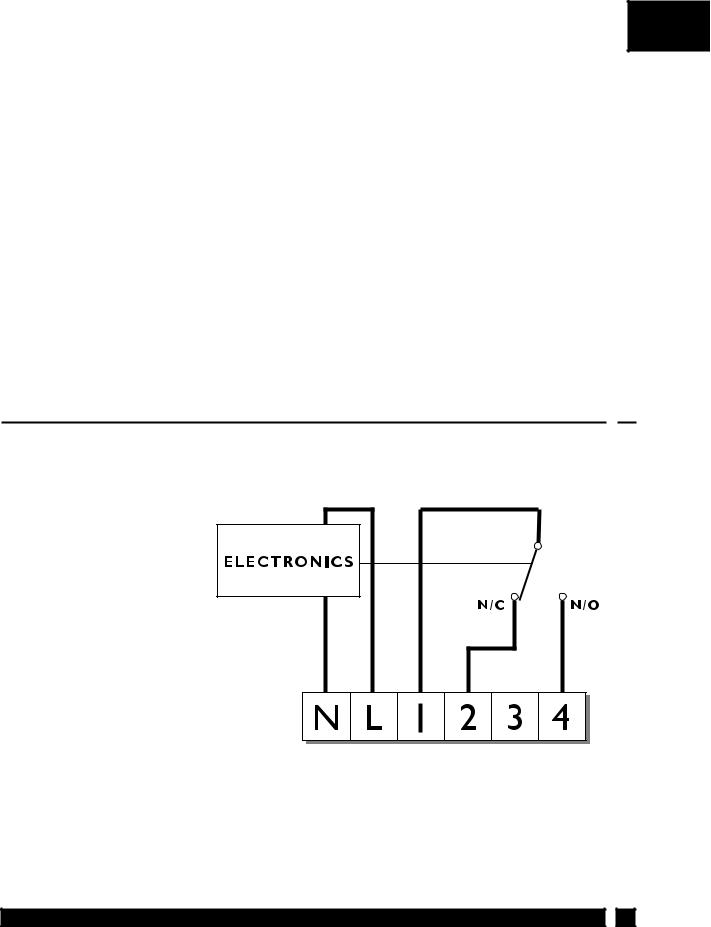
•For wiring connections refer to diagram below.
TS715 Si models are double insulated and do not require an earth connection, however a parking terminal is provided on the wallplate. This is clearly marked with an Earth symbol.
•Prior to mounting the plug-on module, DIL switches on the rear of the plug-on module must be set. See diagram on page 6 for available options.
•Mount plug-on module to wallplate by locating tabs on top of wallplate in apertures on rear of module, hinge down and press firmly to wallplate before tightening securing screws on bottom of wallplate.
3.1 Wiring
For wiring conversion tables please see pages 10-13).
Please Note:
Link terminals L and 1 for standard mains voltage operated systems.
On 24 volt models power supply must be wired to A & B on wallplate.
TS715 (3066 12/01)
230 V |
COM OFF |
ON |
fused 3A |
|
|
Please Note:
Always switch o mains first and never fit programmer to a live wallplate.
Danfoss Heating |
5 |
 Loading...