


 Loading...
Danfoss Series 51-1 Controls B1, Series 51-1 Controls B2, Series 51-1 Controls B7, Series 51-1 Controls E1, Series 51-1 Controls E2 Service guide
...MAKING MODERN LIVING POSSIBLE
Service Manual
Series 51-1 Controls B1, B2, B7, E1, E2, E7, F1, F2, N1, T1, T2, T7, TA, TH, P7, P8
powersolutions.danfoss.com

Service Manual |
Series 51-1 Controls B1, B2, B7, E1, E2, E7, F1, F2, N1, T1, T2, T7, TA, TH, P7, P8 |
|
|
Revision history |
Table of revisions |
|
|
|
|
|
|
|
Date |
Changed |
Rev |
|
|
|
|
|
February 2015 |
Danfoss layout |
BA |
|
|
|
|
|
January 2008 |
First edition |
AA |
|
|
|
|
2 |
11009443 • Rev BA • February 2015 |

Service Manual |
Series 51-1 Controls B1, B2, B7, E1, E2, E7, F1, F2, N1, T1, T2, T7, TA, TH, P7, P8 |
|
Contents |
|
|
Introduction |
|
|
|
Safety precautions............................................................................................................................................................................ |
4 |
|
Unintended machine movement.......................................................................................................................................... |
4 |
|
Flammable cleaning solvents................................................................................................................................................. |
4 |
|
Fluid under pressure.................................................................................................................................................................. |
4 |
|
Personal safety............................................................................................................................................................................. |
4 |
|
Hazardous material.................................................................................................................................................................... |
4 |
|
Symbols used in Danfoss literature............................................................................................................................................ |
5 |
|
General instructions........................................................................................................................................................................ |
5 |
|
Keep it clean.................................................................................................................................................................................. |
5 |
|
Inspect for system contamination........................................................................................................................................ |
6 |
|
Replace the O-rings and gaskets........................................................................................................................................... |
6 |
|
Lubricate all moving parts....................................................................................................................................................... |
6 |
|
Torque procedure....................................................................................................................................................................... |
6 |
|
Overview.............................................................................................................................................................................................. |
6 |
Required tools, gauge port and orifice locations |
|
|
|
Required tools.................................................................................................................................................................................... |
8 |
|
Port locations and gauge installation....................................................................................................................................... |
8 |
|
Orifice locations................................................................................................................................................................................ |
9 |
N1 two-position control |
|
|
|
Functional Description................................................................................................................................................................. |
10 |
|
Adjustments..................................................................................................................................................................................... |
10 |
|
Minor repair...................................................................................................................................................................................... |
10 |
E1, E2, E7, F1, F2 two-position controls |
|
|
|
Functional description................................................................................................................................................................. |
13 |
|
Adjustments..................................................................................................................................................................................... |
14 |
|
Minor repair...................................................................................................................................................................................... |
14 |
B1, B2, B7 two-position controls |
|
|
|
Functional description................................................................................................................................................................. |
17 |
|
Adjustments..................................................................................................................................................................................... |
17 |
|
Minor repair...................................................................................................................................................................................... |
17 |
T1, T2, T7, TA, TH Pressure Compensator (PC) controls |
|
|
|
Functional Description................................................................................................................................................................. |
20 |
|
Overview...................................................................................................................................................................................... |
20 |
|
Option TA.................................................................................................................................................................................... |
20 |
|
Option TH.................................................................................................................................................................................... |
20 |
|
Option T1T2/T7 ......................................................................................................................................................................... |
21 |
|
Brake pressure defeat.............................................................................................................................................................. |
21 |
|
Schematics.................................................................................................................................................................................. |
23 |
|
Adjustment....................................................................................................................................................................................... |
24 |
|
PC start pressure....................................................................................................................................................................... |
24 |
|
Minor repair...................................................................................................................................................................................... |
26 |
|
Control housing........................................................................................................................................................................ |
26 |
|
TA option components........................................................................................................................................................... |
27 |
|
TH option components.......................................................................................................................................................... |
28 |
|
T1, T2, T7 option components............................................................................................................................................. |
29 |
|
Servo/PC supply option CA (with hydraulic signal)..................................................................................................... |
30 |
|
Servo/PC supply option C2 (without external signal)................................................................................................. |
31 |
|
Servo/PC supply options D1/D2/D7.................................................................................................................................. |
32 |
|
Servo/PC supply options L5/R5........................................................................................................................................... |
34 |
11009443 • Rev BA • February 2015 |
3 |

Service Manual |
Series 51-1 Controls B1, B2, B7, E1, E2, E7, F1, F2, N1, T1, T2, T7, TA, TH, P7, P8 |
|
|
Introduction
Safety precautions
Always consider safety precautions before beginning a service procedure. Protect yourself and others from injury. Take the following general precautions whenever servicing a hydraulic system.
Unintended machine movement
W Warning
Unintended movement of the machine or mechanism may cause injury to the technician or bystanders. To protect against unintended movement, secure the machine or disable/disconnect the mechanism while servicing.
Flammable cleaning solvents
W Warning
Some cleaning solvents are flammable. To avoid possible fire, do not use cleaning solvents in an area where a source of ignition may be present.
Fluid under pressure
W Warning
Escaping hydraulic fluid under pressure can have sufficient force to penetrate your skin causing serious injury and/or infection. This fluid may also be hot enough to cause burns. Use caution when dealing with hydraulic fluid under pressure. Relieve pressure in the system before removing hoses, fittings, gauges, or components. Never use your hand or any other body part to check for leaks in a pressurized line. Seek medical attention immediately if you are cut by hydraulic fluid.
Personal safety
W Warning
Protect yourself from injury. Use proper safety equipment, including safety glasses, at all times.
Hazardous material
W Warning
Hydraulic fluid contains hazardous material. Avoid prolonged contact with hydraulic fluid. Always dispose of used hydraulic fluid acm³ording to state, and federal environmental regulations.
4 |
11009443 • Rev BA • February 2015 |

Service Manual |
Series 51-1 Controls B1, B2, B7, E1, E2, E7, F1, F2, N1, T1, T2, T7, TA, TH, P7, P8 |
|
|
Introduction
Symbols used in Danfoss literature
WARNING may result in injury
CAUTION may result in damage to product or property
Reusable part
Non-reusable part, use a new part
Non-removable item
Option - either part may exist
Superseded - parts are not interchangeable Measurement required
Flatness specification
Parallelism specification
External hex head
Internal hex head
Torx head
O-ring boss port
Tip, helpful suggestion
Lubricate with hydraulic fluid
Apply grease / petroleum jelly
Apply locking compound
Inspect for wear or damage
Clean area or part
Be careful not to scratch or damage Note correct orientation
Mark orientation for reinstallation Torque specification
Press in - press fit
Pull out with tool – press fit
Cover splines with installation sleeve
Pressure measurement/gauge location or specification
The symbols above appear in the illustrations and text of this manual. They are intended to communicate helpful information at the point where it is most useful to the reader. In most instances, the appearance of the symbol itself denotes its meaning. The legend above defines each symbol and explains its purpose.
General instructions
Keep it clean
 You can complete many repairs or adjustments without removing the unit from the machine, if the unit is accessible and you can thoroughly clean it before beginning any procedures.
Cleanliness is a primary means of assuring satisfactory motor life on either new or repaired units. Clean the outside of the motor thoroughly before disassembly. Take care to avoid contamination of the system ports. Cleaning parts with a clean solvent wash and air drying is usually adequate.
As with any precision equipment, keep all parts free of foreign materials and chemicals. Protect all exposed sealing surfaces and open cavities from damage and foreign material. Cap all hoses after removal, and plug all open ports. Cover any unattended parts with a protective layer of plastic.
11009443 • Rev BA • February 2015 |
5 |

Service Manual |
Series 51-1 Controls B1, B2, B7, E1, E2, E7, F1, F2, N1, T1, T2, T7, TA, TH, P7, P8 |
|
|
Introduction
Inspect for system contamination
 Inspect the motor for signs of system contamination. If you find contamination, fully disassemble, clean and inspect all components of the motor.
Replace the O-rings and gaskets

 Replace all O-rings and gaskets. Discard them only after you make certain that you have the correct replacement parts. Lightly lubricate all O-rings with clean petroleum jelly before assembly.
Lubricate all moving parts
 During reassembly, coat all moving parts with a film of clean hydraulic oil. This helps lubricate the surfaces during start-up.
 For fluid quality requirements, refer to 520L0463 Hydraulic Fluids and Lubricants, Technical
Information.
Torque procedure
 During reassembly, cross torque all retaining screws to the given value. Do not overtorque.
Overview
Series 51-1 motor controls operate by routing the flow of oil to the servo piston in the motor’s endcap. The servo piston has a differential area of 2:1.
•The larger area acts to reduce displacement.
•The smaller area works to increase displacement.
Due to the simplified design of the Series 51-1, only two-position and pressure compensator controls are available.
An external hydraulic or electric signal operates two-position controls. Pressure comes from the low side of the system loop and the control routes it to either the rod or piston end of the servo piston to set the motor’s displacement.
Pressure compensator (PC) controls automatically set the displacement of the motor based on system pressure. PC controls allow the motor to increase available torque based on system demand by increasing the motor’s displacement.
The motor defaults to minimum displacement until system pressure reaches the PC set pressure. The PC set pressure is adjustable in a range from 110 to 370 bar [1595 to 5365 psi]. Pressure is taken from the high side of the system loop to operate the servo piston.
PC controls:
6 |
11009443 • Rev BA • February 2015 |

Service Manual |
Series 51-1 Controls B1, B2, B7, E1, E2, E7, F1, F2, N1, T1, T2, T7, TA, TH, P7, P8 |
|
|
Introduction
•can have a maximum displacement lock that holds the displacement at maximum when a hydraulic or electric signal is applied.
•can be equipped with a brake pressure defeat option that holds the motor at minimum displacement during dynamic braking. A hydraulic or electric signal operates the brake pressure defeat feature.
Differential area servo piston
Value segment
Servo piston
11009443 • Rev BA • February 2015 |
7 |

Service Manual |
Series 51-1 Controls B1, B2, B7, E1, E2, E7, F1, F2, N1, T1, T2, T7, TA, TH, P7, P8 |
|
|
Required tools, gauge port and orifice locations
Required tools
You can perform the service procedures in this manual using common mechanic’s hand tools. Special tools, if required, are shown. Calibrate pressure gauges frequently to ensure accuracy. Use snubbers to protect pressure gauges. For controls N*, E*, F*, and B* use a 600 psi [45 bar] gauge for M3, M4, and M5 gauge (pressure) ports. For T* controls use a 10,000 psi [600 bar] gauge for M3 and M4 gauge (pressure) ports..
Port locations and gauge installation
Two-position controls
|
M3 Gauge port |
M3 Gauge port |
|
Servo pressure min-angle |
Servo pressure min-angle |
M3 Gauge port |
0.5625 [9/16] 18UNF-2B |
0.5625 [9/16] 18UNF-2B |
|
|
|
Servo pressure min-angle |
|
|
0.5625 [9/16] 18UNF-2B |
|
|
|
M5 Gauge port |
M5 Gauge port |
|
Servo supply pressure |
Servo supply pressure |
M5 Gauge port |
0.5625 [9/16] 18UNF-2B |
0.5625 [9/16] 18UNF-2B |
|
|
|
Servo supply pressure |
|
|
0.5625 [9/16] 18UNF-2B |
|
|
MON* |
MOE* |
|
|
MOF* |
MOB* |
M4 Gauge port |
M4 Gauge port |
|
Servo pressure max-angle |
||
Servo pressure max-angle |
||
0.5625 [9/16] 18UNF-2B |
||
0.5625 [9/16] 18UNF-2B |
||
|
P101 242E N1 Control

 Pressure Compensator
adjusting screw
M3 Gauge port
Servo pressure min-angle
0.5625 [9/16] 18UNF-2B
M4 Gauge port
Servo pressure max-angle
0.5625 [9/16] 18UNF-2B
T* Controls |
P101 244Ea |
8 |
11009443 • Rev BA • February 2015 |

Service Manual |
Series 51-1 Controls B1, B2, B7, E1, E2, E7, F1, F2, N1, T1, T2, T7, TA, TH, P7, P8 |
|
|
Required tools, gauge port and orifice locations
Orifice locations
T3
|
U5 |
|
U5 |
U5 |
U5 |
B* control codes
|
T2 |
|
T3 |
|
U5 |
|
U5 |
T3 |
T2 |
N* control codes
U5 
T2
T3 
T3 |
T2 |
E* and F* control codes
T3
T3 
E100 293E
T* control codes
11009443 • Rev BA • February 2015 |
9 |
Service Manual |
Series 51-1 Controls B1, B2, B7, E1, E2, E7, F1, F2, N1, T1, T2, T7, TA, TH, P7, P8 |
|
|
N1 two-position control
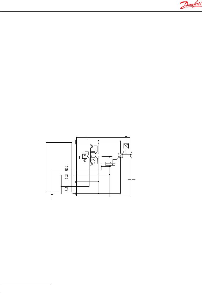
Functional Description
The N1 control consists of a ported housing that is mounted on the endcap over the piston end of the servo piston.
The housing contains two external ports, designated M3 and M5. These ports serve as the control inputs. There are three interface ports1 that connect to the rod and piston ends of the servo, and to the servo supply port in the endcap. The servo supply connects to the output of the loop flushing spool so it dispenses low loop pressure to the control regardless of motor direction.
The control routes servo supply pressure through orifices U5 and T2 to the rod end of the servo piston. This holds the motor at maximum displacement until pressure from an external source is applied at port M3. This signal pressure then routes through orifice T3 to the piston end of the servo, shifting the motor to minimum displacement. Typically 20 to 25 bar [290 to 360 psi] is necessary to shift the motor.
You may also install a plug in place of orifice U5, blocking the connection to servo supply. You can then apply pressure from an external source at port M5 to shift the motor to maximum displacement.
Orifices T2 and T3 set the control response by limiting the flow to either end of the servo piston.
Schematic diagram |
|
|
N1 control schematic diagram |
|
|
|
L2 |
N |
|
A |
|
|
|
n |
|
|
min. |
|
|
disp. |
|
T3 |
|
|
T2 |
|
|
|
L1 |
|
U5 |
|
M5 |
B |
M4 |
X1(M3) |
|
|
|
|
P001 779E |
Adjustments
This control requires no adjustments.
Minor repair
Disassembly
1.Thoroughly clean all external surfaces before disassembly. Mark components as necessary to ensure you reassemble the unit correctly.
2.Remove the 4 screws (M16). Use an 8mm internal hex wrench.
3.Remove the control housing (M1N*) from the endcap.
1 Interface ports are those between the control and the endcap.
10 |
11009443 • Rev BA • February 2015 |
Service Manual |
Series 51-1 Controls B1, B2, B7, E1, E2, E7, F1, F2, N1, T1, T2, T7, TA, TH, P7, P8 |
|
|
N1 two-position control
4.After ensuring you have the correct replacement parts, remove and discard the interface O-rings (G42), or remove the control gasket (G420) from the endcap.
5.Using a 1/4-inch internal hex wrench remove plugs (M14) from the housing. Fasteners are metric. Porting plugs are SAE.
6.Using a 1/8-inch internal hex wrench remove plug (M12) from the housing.
7.After ensuring you have the correct replacement parts, remove and discard O-rings (M12A and M14A) from the plugs (M12 and M14).
8.If necessary, remove T2, T3, and U5 control orifices. Use a 3mm internal hex wrench. Tag the orifices for reassembly.
N1 control exploded |
|
M14 |
|
|
M16 |
|
M12 |
|
M1N* |
G42 |
M14 |
G420 |
|
P101176
Inspection
Clean and inspect all parts for damage. Check orifices and passages in control housing for foreign material.
Assembly
1.If removed, install control orifices T2, T3, and U5 to their proper location. Using a 3mm internal hex wrench, torque the orifices to 6 N•m [4 lbf•ft].
2.Lubricate and install new O-rings on the housing plugs (M12). Using a 1/8-inch internal hex wrench, torque them to 9 N•m [7 lbf•ft]
3.Lubricate and install new O-rings on the housing plugs (M14). Using a 1/4-inch internal hex wrench, torque them to 37 N•m [28 lbf•ft].
4.Using clean petroleum jelly to retain them, install new interface O-rings (G42) or a new control gasket (G420) on the endcap.
11009443 • Rev BA • February 2015 |
11 |
Loading...