


RX1, 2 & 3
Electronic radio-frequency receivers (1,2 or 3-channel)
GB |
Installation Instructions |
NL |
|
Commissioning Instructions |
|
F |
Instructions d’installation |
GR |
|
Instructions d’utilisateur |
|
D |
Installationsanweisungen |
PL |
|
Inbetriebnahme-Instruktion |
|
ES |
Instrucciones de instalación |
LT |
Instrucciones del usuario |
||
DK |
Instruktions vejledning |
I |
Aktiveringsinstruktioner |
Installatiehandleiding
Inbedrijfstelling
ПдзгЯет егкбфЬуфбузт
Οδηγίες έναρξης λειτουργίας
Instrukcja instalacji
Instrukcja
Montavimo instrukcijos Komplektavimo instrukcijos
Istruzioni per l’uso Istruzioni per l’ordinazione

GB - Installation Instructions / F - Instructions d’installation / |
3-4 |
D- Installationsanweisungen / ES - Instrucciones de instalación / |
|
DK - Instruktions vejledning / NL - Installatie handleiding / |
|
GR - ПдзгЯет егкбфЬуфбузт / PL - Instrukcja instalacji / |
|
LT - Montavimo instrukcijos / I - Istruzioni per l’uso |
|
GB - Wiring Details / F - Détails du câblage interne / |
5-7 |
D - Elektrischer Anschluss / ES - Detalles de conexionado / |
|
DK - Ledningsforbindelser / NL - Bedradingsschema / |
|
GR - Λεπτομέρειες ηλεκτρικής σύνδεσης / PL - Szczegóły połączeń / |
|
LT - Informacija apie laidus / I - Dettagli collegamento |
|
GB |
|
Specification |
9 |
Commissioning |
10 |
F |
|
Spécifications |
11 |
Instructions |
12 |
D |
|
Technische Daten |
13 |
Inbetriebnahme-Instruktion |
14 |
ES |
|
Especificaciones |
15 |
Instrucciones de puesta en marcha |
16 |
DK |
|
Specification |
17 |
Aktiveringsinstruktioner |
18 |
NL |
|
Technische gegevens |
19 |
Inbedrijfstelling |
20 |
GR |
21 |
РспдйбгсбцЮ |
|
Οδηγίες έναρξης λειτουργίας |
22 |
PL |
|
Specyfikacja |
23 |
Instrukcja |
24 |
LT |
|
Specifikacija |
25 |
Komplektavimo instrukcijos |
26 |
I |
|
Specificazioni |
27 |
Istruzioni per l’ordinazione |
28 |
2
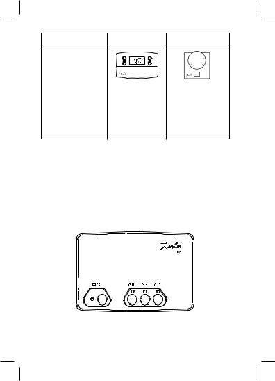
A |
B |
C |
TP5000-RF |
TP7000-RF |
RET B-RF |
TP5.2-RF |
TP75-RF |
CET B-RF |
TP5E-RF |
WP75-RF |
|
RT51-RF |
|
(LEARN |
RT52-RF |
|
button under |
RT1-RF |
|
setting dial) |
RT2-RF |
|
|
433.92 MHz
30m (max)
|
|
|
|
RX1 |
RX2 |
RX2C |
|
RX3 |
RX3B |
RX3B-VF |
|
3

4
(GB) Wiring Details / (F) Détails du câblage interne / (D) Elektrischer Anschluss /
(ES) Detalles de conexionado / (DK) Ledningsforbindelser / (NL) Aansluitschema / (GR) ЛерфпмЭсейет ухсмЬфщузт / (PL) Szczegóły połączeń / (LT) Informacija
apie laidus / (I) Dettagli collegamento
GB |
F |
D |
ES |
DK |
|
|
|
|
|
Electronics |
Electronique |
Elektronik |
Electrónica |
Elektronik |
|
|
|
|
|
COM |
COM |
Potentialfreie Kontakte |
Común |
Potentialefri kontakt |
|
|
|
|
|
On |
Marche |
EIN |
On |
Tændt |
|
|
|
|
|
Off |
Arrêt |
AUS |
Off |
Slukket |
|
|
|
|
|
Zone |
Zone |
Zone |
Zona |
Zone |
|
|
|
|
|
Boiler |
Chaudière |
Heizgerät |
Caldera |
Kedel |
|
|
|
|
|
CH |
Chauffage Central |
Zentralheizung |
Calefacción central |
Centralvarme |
|
|
|
|
|
HW |
Eau Chaude |
Heisswasser |
Agua caliente |
Varmt brugsvand |
|
|
|
|
|
|
|
|
|
|
NL |
GR |
PL |
LT |
IT |
|
|
|
|
|
Elektronica |
Ηλεκτρονικά |
Układy elektroniczne |
Elektroninė sistema |
Elettronica |
|
|
sterownika |
|
|
|
|
|
|
|
COM |
COM (Κοινό) |
Styk beznapięciowy |
COM (įprasta) |
COM |
|
|
|
|
|
Aan |
ON |
Styk: załącz |
On |
On |
|
|
|
|
|
Uit |
OFF |
Styk: wyłącz |
Off |
Off |
|
|
|
|
|
Zone |
Ζώνη |
Strefa |
Zona |
Zona |
|
|
|
|
|
Ketel |
Μπόιλερ |
Bojler |
Boileris |
Caldaia |
|
|
|
|
|
Centrale |
Κεντρική θέρμανση |
Centralne ogrzewanie |
Centrinis šildymas |
Riscaldamento |
verwarming |
|
|
|
centrale |
Warm tapwater |
Ζεστό νερό |
Gorąca woda |
Karštas vanduo |
Acqua calda |
|
|
|
|
|
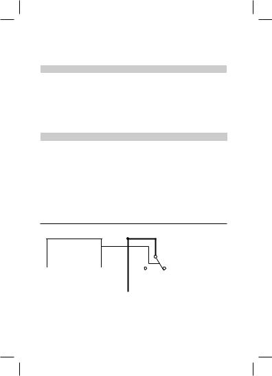
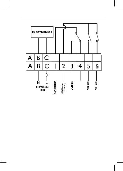
RX1
ELECTRONICS
|
|
|
|
|
|
|
|
|
|
|
|
|
|
|
|
|
|
|
|
|
|
|
|
|
N |
L |
1 |
2 |
3 |
4 |
|||||
|
|
|
|
|
|
|
COM |
ZONE |
ZONE |
||
|
|
|
|
|
|
|
|
1 ON |
1 OFF |
||
Note: For mains voltage applications link terminals L and 2.
5
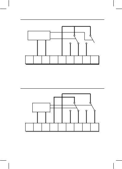
RX2
Note: for mains voltage applications link terminals L and 2.
ELECTRONICS |
|
|
|
|
|
|
A B C |
1 |
2 |
3 |
4 |
5 |
6 |
N |
L |
COM ZONE |
ZONE |
ZONE |
|
|
1 ON |
1 OFF |
2 ON |
ATTENTION: If replacing a previous version of the RX2 receiver please use the new backplate supplied and wire as illustrated above.
RX2C
|
ELECTRONICS |
|
|
|
|
|
|
A |
B C |
1 |
2 |
3 |
4 |
5 |
6 |
N |
L |
COM COM |
ZONE 1 ZONE |
1 ZONE 2 ZONE |
2 |
||
|
|
ZONE 1 ZONE 2 |
ON |
OFF |
ON |
OFF |
|
6
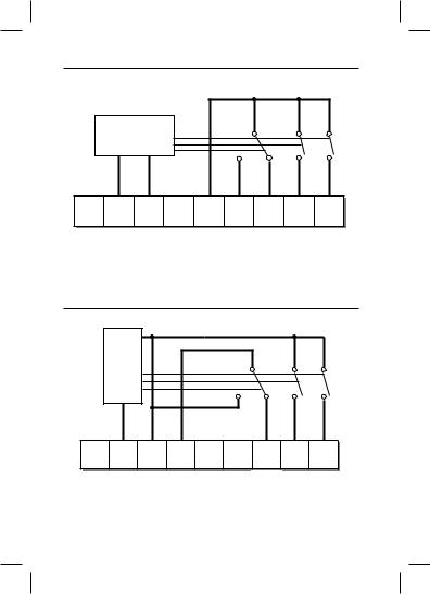
RX3 |
|
|
|
|
|
|
|
|
|
ELECTRONICS |
|
|
|
|
|
|
|
A |
B |
C |
1 |
2 |
3 |
4 |
5 |
6 |
|
N |
L |
|
COM |
ZONE |
ZONE |
ZONE |
ZONE |
|
|
|
|
|
1 ON |
1 OFF |
2 ON |
3 ON |
RX3B |
|
|
|
|
|
|
|
|
|
ELECTRONICS |
|
|
|
|
|
|
|
A |
B |
C |
1 |
2 |
3 |
4 |
5 |
6 |
|
N |
L |
HW |
|
|
PumpPL |
HTG BOILERBoiler |
|
|
|
|
|
|
|
FROMLive |
|
Switched |
|
|
|
|
|
|
BOILERFrom |
|
Live |
|
|
|
|
|
|
Boiler |
|
|
7
RX3B-VF
8

GB - Specification
ENGLISH |
SPECIFICATION |
|
|
Radio Controlled Room Thermostat Receiver Module for: see list page 3
Supply Voltage |
230 Vac ± 15%, 50Hz |
|
|
Construction |
BS EN 60730-2-1, EN 300-220-1 |
|
|
Maximum Ambient Temperature |
45°C |
|
|
Switch Type |
RX1 - 1 x SPDT, type 1B |
|
|
|
RX2 - 1 x SPDT, 1 x SPST, type 1B |
|
|
|
RX3 - 1 x SPDT, 2 x SPST, type 1B |
|
|
Switch Rating |
264 Vac, 3 (1) A (Total current) |
|
|
IP Rating |
IP 40 |
|
|
Control Pollution Situation |
Degree 2 |
|
|
Max. Range |
30 metres |
|
|
Operating Frequency |
433.92 MHz |
|
|
Software Classification |
Class A |
|
|
Rated Impulse Voltage |
2.5kV |
|
|
Ball Pressure Test |
75°C |
|
|
GB
Specification
9
GB GB - Commissioning Instructions
Commissioning Instructions
Thermostat (refer to page 3 for thermostat type)
Step 1. Type A Press & hold buttons and + for 3 seconds Type B Press & hold LEARN button for 3 seconds Type C Remove dial, press & hold LEARN button for 3
seconds (located under setting dial)
Do not replace knob until Learn process is complete
NOTE: Thermostat now transmits continuously for 5 minutes.
Receiver
Step 2. RX1
Press and hold buttons PROG and CH1 for 3 seconds
until green light flashes
Step 3. RX2 / RX3 (if applicable)
Stat 1 - perform steps 1-2 for CH1
Stat 2 (RX2 & RX3)
|
Wait 5 mins, perform step 1, then press |
|
PROG + CH2 on RX2/RX3 |
Stat 3 (RX3 only) |
|
|
Wait 5 mins, perform step 1, then press |
|
PROG + CH3 on RX3 |
Use only |
Zone status |
during |
LEDs, lit when |
programming |
‘ON’ |
Receiver status |
Emergency ‘ON’ button, press |
if communication fails, turns |
|
LED, flashes when |
on heat, returns to AUTO when |
receiving |
communication is re-established. |
10
 Loading...