


Installation Guide
SVA-ST/SVA-SS 15 - 200
ICFS 20, ICFR 20, ICFN 20
| <![if ! IE]> <![endif]>148R9504 |
Installation |
||||||||||||||||||||||||||||||||||||||||||||||||||||||
|
|||||||||||||||||||||||||||||||||||||||||||||||||||||||
|
|
|
|
|
|
|
|
|
|
|
|
|
|
|
|
|
|
|
|
|
|
|
|
|
|
|
|
|
|
|
|
|
|
|
|
|
|
|
|
|
|
|
|
|
|
|
|
|
|
|
|
|
|
|
|
|
|
|
|
|
|
|
|
|
|
|
|
|
|
|
|
|
|
|
|
|
|
|
|
|
|
|
|
|
|
|
|
|
|
|
|
|
|
|
|
|
|
|
|
|
|
|
|
|
|
|
|
|
|
|
|
|
|
|
|
|
|
|
|
|
|
|
|
|
|
|
|
|
|
|
|
|
|
|
|
|
|
|
|
|
|
|
|
|
|
|
|
|
|
|
|
|
|
|
|
|
|
|
|
|
|
|
|
|
|
|
|
|
|
|
|
|
|
|
|
|
|
|
|
|
|
|
|
|
|
|
|
|
|
|
|
|
|
|
|
|
|
|
|
|
|
|
|
|
|
|
|
|
|
|
|
|
|
|
|
|
|
|
|
|
|
|
|
|
|
|
|
|
|
|
|
|
|
|
|
|
|
|
|
|
|
|
|
|
|
|
|
|
|
|
|
|
|
|
|
|
|
|
|
|
|
|
|
|
|
|
|
|
|
|
|
|
|
|
|
|
|
|
|
|
|
|
|
|
|
|
|
|
|
|
|
|
|
|
|
|
|
|
|
|
|
|
|
|
|
|
|
|
|
|
|
|
|
|
|
|
|
|
|
|
|
|
|
|
|
|
|
|
|
|
|
|
|
|
|
|
|
|
|
|
|
|
|
|
|
|
|
|
|
|
|
|
|
|
|
|
|
|
|
|
|
|
|
|
|
|
|
|
|
|
|
|
|
|
|
|
|
|
|
|
|
|
|
|
|
|
|
|
|
|
|
|
|
|
|
|
|
|
|
|
|
|
|
|
|
|
|
|
|
|
|
|
|
|
|
|
|
|
|
|
|
|
|
|
|
|
|
|
|
|
|
|
|
|
|
|
|
|
|
|
|
|
|
|
|
|
|
|
|
|
|
|
|
|
|
|
|
|
|
|
|
|
|
|
|
|
|
|
|
|
|
|
|
|
|
|
|
|
|
|
|
|
|
|
|
|
|
|
|
|
|
|
|
|
|
|
|
|
|
|
|
|
|
|
|
|
|
|
|
|
|
|
|
|
|
|
|
|
|
|
|
|
|
|
|
|
|
|
|
|
|
|
|
|
|
|
|
|
|
|
|
|
|
|
|
|
|
|
|
|
|
|
|
|
|
|
|
|
|
|
|
|
|
|
|
|
|
|
|
|
|
|
|
|
|
|
|
|
|
|
|
|
|
|
|
|
|
|
|
|
|
|
|
|
|
|
|
|
|
|
|
|
|
|
|
|
|
|
|
|
|
|
|
|
|
|
|
|
|
|
|
|
|
|
|
|
|
|
|
|
|
|
|
|
|
|
|
|
|
|
|
|
|
|
|
|
|
|
|
|
|
|
|
|
|
|
|
|
|
|
|
|
|
|
|
|
|
|
|
|
|
|
|
|
|
|
|
|
|
|
|
|
|
|
|
|
|
|
|
|
|
|
|
|
|
|
|
|
|
|
|
|
|
|
|
|
|
|
|
|
|
|
|
|
|
|
|
|
|
|
|
|
|
|
|
|
|
|
|
|
|
|
|
|
|
|
|
|
|
|
|
|
|
|
|
|
|
|
|
|
|
|
|
|
|
|
|
|
|
|
|
|
|
|
|
|
|
|
|
|
|
|
|
|
|
|
|
|
|
|
|
|
|
|
|
|
|
|
|
|
|
|
|
|
|
|
|
|
|
|
|
|
|
|
|
|
|
|
|
|
|
|
|
|
|
|
|
|
|
|
|
|
|
|
|
|
|
|
|
|
|
|
|
|
|
|
|
|
|
|
|
|
|
|
|
|
|
|
|
|
|
|
|
|
|
|
|
|
|
|
|
|
|
|
|
|
|
|
|
|
|
|
|
|
|
|
|
|
|
|
|
|
|
|
|
|
|
|
|
|
|
|
|
|
|
1 |
2 |
|
3 |
|
|
|
|
|
|
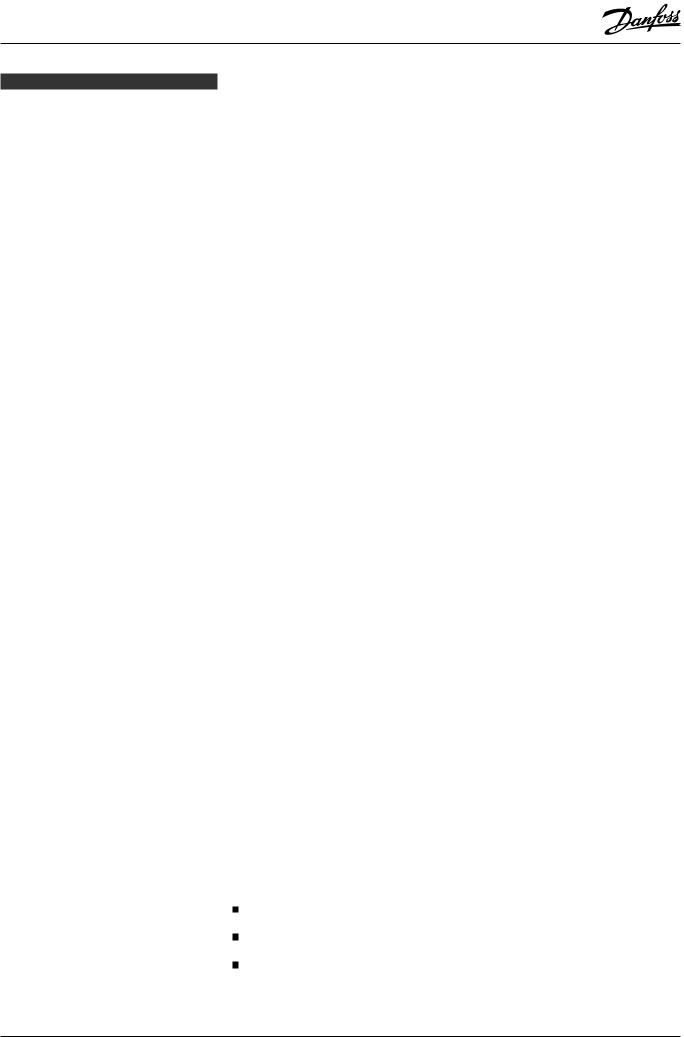
Nm |
LB-feet |
|
|
|
DN 15-20 |
22 |
16 |
|
|
|
DN 25-32-40-50 |
44 |
32 |
|
|
|
DN 65 |
75 |
53 |
|
|
|
DN 80 |
44 |
32 |
|
|
|
DN 100 |
75 |
53 |
|
|
|
DN 125-150 |
183 |
135 |
4 |
5a |
5b |
DN 200 |
370 |
272 |
|
|
|
Vedligeholdelse, Maintenance, Wartung, Entretien
6 |
7 |
8 |
9 |
Kun DN 80 - 200
Only DN 80 - 200
Nur DN 80 - 200
Uniquement DN 80 - 200
|
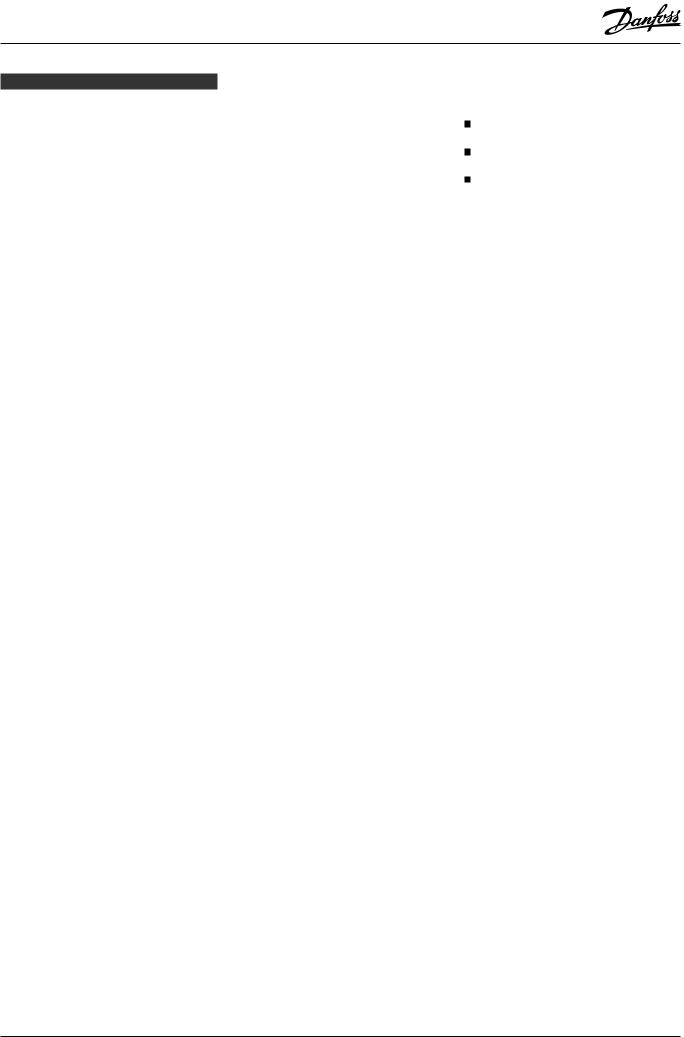
Nm |
LB-feet |
DN 15-20 |
50 |
37 |
DN 25-40 |
70 |
52 |
DN 50-65-80-100 |
60 |
45 |
DN 125-150-200 |
80 |
60 |
10 |
11 |
<![endif]>148R9504
© Danfoss A/S (RC-MDP/MWA), 2014-11 |
DKRCI.PI.KD0.A4.52 / 520H0745 |
1 |
DANSK
Installation
Kølemidler
Kan anvendes til alle almindelige, ikkebrændbare kølemidler, herunder R717, H2S og ikke-korroderende gasser/væsker under passende hensyntagen til tætnings-materialer. Brændbare kulbrinter bør ikke anvendes. Det anbefales, kun at anvende ventilen i lukkede kredsløb.
Yderligere informationer fås ved at kontakte Danfoss.
Temperaturområde
SVA-ST: –50/+150°C (–58/+302°F)
SVA-LT: –60/+150°C (–76/+302°F)
SVA-SS: –60/+150°C (–76/+302°F)
Trykområde
Ventilerne er beregnet til et maks. arbejdstryk på 40 bar g (580 psi g). Dette gælder såvel standardversionen (SVA-ST) som lavtemperaturversionerne (SVA-LT, SVA-SS).
Installation
Ventilen skal installeres med spindlen opad eller i vandret stilling (fig. 1). Ventiler bør åbnes manuelt uden brug af værktøj eller andre anordninger. Ventilen kan modstå et højt indvendigt tryk. Rørsystemet bør imidlertid konstrueres, så væskefælder undgås og risikoen for hydraulisk tryk for-årsaget af termisk ekspansion reduceres. Ventilen skal beskyttes mod tryktransienter, såsom “væskeslag”, i systemet.
Bemærk!
SVA er stopventiler og skal altid være helt lukket eller helt åbne. Halvåbne stillinger er ikke tilladt. Hvis ventilen monteres tæt på kompressoren (economizer-ledninger, olieledninger etc.) eller på andre ledninger, der udsættes for stærke vibrationer og pulseringer, er det nødvendigt at montere særlige låseskiver på ventilen. Yderligere oplysninger kan findes i kataloget.
Anbefalet flowretning
For at opnå optimale flowbetingelser bør ventilen installeres, så flowet styres hen imod ventilkeglen, som angivet af pilen på siden af ventilhuset (fig. 2). Flow i modsat retning er også acceptabelt
(fig. 2), men reducerer kv- / Cv-værdien let.
Svejsning
For at forhindre, at teflonpakningen i ventilsædet og O-ringene mellem ventilhuset og dækslet samt i pakdåsen beskadiges, bør dækslet fjernes før svejsning (fig. 4). Der må kun anvendes materialer og svejse-metoder, som er kompatible med det materiale, som ventilhuset er lavet af. Når svejsear-bejdet er færdigt, bør ventilen rengøres indvendigt for at fjerne svejseslagger, før den samles igen.
Undgå, at der trænger svejseslagger og snavs ind i ventilhusets og dækslets gevind.
Det er ikke nødvendigt at fjerne dækslet, forudsat at:
Temperaturen i området mellem ventil-huset og dækslet ikke overstiger +150°C/+302°F under svejsning. Temperaturen afhænger af den valgte svejsemetode samt af, hvorvidt ventil-huset køles under selve svejsningen. (Køling kan opnås
for eksempel ved at vikle en våd klud omkring ventilhuset.) Undgå, at der trænger snavs, svejseslagger osv. ind i ventilen under svejsning.
Pas på ikke at beskadige teflonkegle-ringen. Efter installation skal ventilhuset være uden spænding (ekstern belastning).
Der må ikke installeres stopventiler i systemer, hvor ventilens udløbsside er åben til atmosfæren. Ventilens udløbsside skal altid tilsluttes systemet eller blændes korrekt af, for eksempel med en påsvejset endebund.
Montering
Fjern svejseslagger og eventuelt snavs fra rør og ventilhus før montering. Kontroller, at keglen er skruet helt tilbage mod dækslet, før den udskiftes i ventil-huset
(fig. 5a).
Tilspænding
Tilspænd dækslet med en momentnøgle til de værdier, der er angivet i tabellen
(fig. 5b).
Farver og identifikation
SVA-ventilerne er fra fabrikken malet med rød oxidgrunder. Rustfrie stålventiler males ikke. Ventilen kan identificeres nøjagtigt ved hjælp af identifikationsringen oven på dækslet samt prægningen på ventilhuset. Når ventilhuset er installeret og monteret, skal dets udvendige overflade beskyttes mod korrosion med et velegnet anti-korrosionsmiddel.
Det anbefales at afdække identifikations-ringen ved ommaling af ventilen.
SVA-SS-ventiler er ikke malet og kræver ingen beskyttende behandling.
Vedligeholdelse
Pakdåse
Udskift hele pakdåsen (fås som reservedel), når der udføres service og vedligeholdelse. Som hovedregel må pakdåsen ikke afmon-teres, hvis der er indvendigt tryk på ventil-en. Pakdåsen kan imidlertid fjernes, mens ventilen stadig er under tryk, hvis der tages følgende forholdsregler:
Spindeltætningsfunktion (fig. 6)
Drej spindlen mod uret, indtil ventilen er helt åben, for at aktivere spindeltætnings-funktionen.
Trykudligning (fig. 7)
I nogle tilfælde dannes der tryk bag pak-dåsen. Følgelig bør der fastgøres et hånd-hjul eller lignende til spindlens top, mens trykket udlignes. Trykket kan udlignes ved langsomt at skrue pakdåsen af.
Afmontering af pakdåse (fig. 8)
Håndhjul og pakdåse kan nu fjernes.
Afmontering af ventil (fig. 9)
Undlad at afmontere dækslet, mens ventilen er under tryk.
Kontroller, at O-ringen (pos. A) ikke er beskadiget.
Kontroller, at spindlen er fri for ridser og slagmærker.
Skift hele kegleenheden ud, hvis teflonkegleringen er beskadiget.
Udskiftning af kegle (fig. 9) |
|
Skru kegleskruen (pos. B) ud med en |
|
unbrakonøgle. |
|
SVA-ST/LT/SS 15-40................................... |
2,0 mm A/F |
SVA-ST/LT 50-65.......................................... |
2,5 mm A/F |
SVA-ST/LT 80-100........................................... |
4 mm A/F |
SVA-ST/LT 125-150 ........................................ |
5 mm A/F |
SVA-ST/LT 200.................................................. |
6 mm A/F |
(Pakningssættet fra Danfoss Industrial Refrigeration indeholder en unbrakonøgle). Fjern kuglerne (pos. C).
Antal kugler i pos. C: |
|
SVA-ST/LT/SS 10-20.............................................. |
10 stk. |
SVA-ST/LT/SS 25-65.............................................. |
14 stk. |
SVA-ST/LT 80-200 ................................................. |
13 stk. |
Keglen kan nu afmonteres. Anbring den nye kegle på spindlen og monter kuglerne. Monter kegleskruen igen med Loctite nr. 648, så den spændes godt til.
Udskiftning af spindeltætning (fig. 10)
Størrelserne DIN 80-200:
Ventilens spindeltætning består af en speciel teflonring. Hvis denne ring er be-skadiget, skal den udskiftes. Skru spindlen ud af dækslet. Afmonter forsigtigt den originale spindeltætning og monter en ny tætning i den vinklede kontaktflade lige inden for åbningen i dækslet. Undgå at bøje og beskadige teflonringen, eller beskadige kontaktoverfladen i ventiltop-pen under monteringen.
Montering
Fjern eventuelt snavs fra huset, før ven-tilen samles. Kontroller, at keglen er skruet tilbage imod dækslet, før den udskiftes i ventilhuset (fig. 5a).
Tilspænding
Tilspænd dækslet med en momentnøgle til de værdier, der er angivet i tabellen (fig. 5b).
Tilspænd pakdåsen med en momentnøgle til de værdier, der er angivet i tabellen (fig. 11).
Anvend kun originale Danfoss-dele, her-under pakdåser, O-ringe og pakninger, ved udskiftning. De materialer, som er anvendt til nye dele, er certificeret til det pågældende kølemiddel.
Kontakt venligst Danfoss i tilfælde af tvivl.
Danfoss påtager sig intet ansvar for fejl og undladelser. Danfoss Industrial Refrigeration forbeholder sig retten til at foretage ændringer i produkter og specifikationer uden forudgående varsel.
2 |
DKRCI.PI.KD0.A4.52 / 520H0745 |
© Danfoss A/S (RC-MDP/MWA), 2014-11 |
ENGLISH
Installation
Refrigerants
Applicable to all common non-flammable refrigerants, including R717, H2S and noncorrosive gases/liquids dependent on sealing material compatability. Flammable hydrocarbons are not recommended. The valve is only recommended for use in closed circuits. For further information please contact Danfoss.
Temperature range
SVA-ST: –50/+150°C (–58/+302°F)
SVA-LT: –60/+150°C (–76/+302°F)
SVA-SS: –60/+150°C (–76/+302°F)
Pressure range
The valves are designed for a max. working pressure of 40 bar g (580 psi g), for both standard (SVA-ST) and low temperature versions (SVA-LT, SVA-SS).
Installation
The valve must be installed with the spindle vertically upwards or in horizontal position (fig. 1). Valves should be opened by hand without the use of tools or other devices (fig. 3). The valve is designed to withstand a high internal pressure. However, the piping system should be designed to avoid liquid traps and reduce the risk of hydraulic pressure caused by thermal expansion. It must be ensured that the valve is protected from pressure transients like “liquid hammer” in the system.
Attention!
SVA are shut off valves and must always be either fully closed or fully open. Half open positions are not allowed. In case the valve is installed close to compressor (economizer lines, oil lines etc.) or on other lines subjected to high vibrations and pulsations, it is necessary to install special lock washers on the valve. Please refer to the catalogue for additional information.
Recommended flow direction
To achieve optimum flow conditions, the valve should be installed with the flow towards the valve cone as indicated by the arrow on the side of the valve body
(fig. 2). Flow in the opposite direction is also acceptable (fig. 2), but slightly reduces the kv- / Cv value.
Welding
The bonnet should be removed before welding (fig. 4) to prevent damage to the O-rings in the packing gland and between the valve body and bonnet, as well as the teflon gasket in the valve seat. Only materials and welding methods, compa-tible with the valve housing material, must be welded to the valve housing. The valve should be cleaned internally to remove welding debris on completion of welding and before the valve is reassembled.
Avoid welding debris and dirt in the threads of the housing and the bonnet.
Removing the bonnet can be omitted provided that:
The temperature in the area between the valve body and bonnet during welding does not exceed +150°C/+302°F. This temperature depends on the welding method as well as on
any cooling of the valve body during the welding itself. (Cooling can be ensured by, for example, wrapping a wet cloth around the valve body.) Make sure that no dirt, welding debris etc. get into the valve during the welding procedure.
Be careful not to damage the teflon cone ring.
The valve housing must be free from stresses (external loads) after installation.
Stop valves must not be mounted in sy-stems where the outlet side of the valve is open to atmosphere. The outlet side of the valve must always be connected to the system or properly capped off, for example with a welded-on end plate.
Assembly
Remove welding debris and any dirt from pipes and valve body before assembly. Check that the cone has been fully screwed back towards the bonnet before it is re-placed in the valve body (fig. 5a).
vTightening
Tighten the bonnet with a torque wrench, to the values indicated in the table
(fig. 5b).
Colours and identification
The SVA valves are painted with a red oxide primer in the factory. Stainless steel valves are not painted. Precise identification of the valve is made via the ID ring at the top of the bonnet, as well as by the stamping on the valve body. The external surface of the valve housing must be guarded against corrosion with a suitable protective coating after installation and assembly.
Protection of the ID ring when repainting the valve is recommended.
SVA-SS valves are not painted and do not require any protective coating.
Maintenance
Packing gland
When performing service and mainte-nance, replace the complete packing gland only, which is available as a spare part. As a general rule, the packing gland must not be removed if there is internal pressure in the valve. However, if the following precautionary measures are taken, the packing gland can be removed with the valve still under pressure:
Backseating (fig. 6)
To backseat the valve, turn the spindle counterclockwise until the valve is fully open.
Pressure equalization (fig. 7)
In some cases, pressure forms behind the packing gland. Hence a handwheel or similar should be fastened on top of the spindle while the pressure is equal-ized. The pressure can be equalized by slowly screwing out the gland.
Removal of packing gland (fig. 8)
Handwheel and packing gland can now be removed.
Dismantling the valve (fig. 9)
Do not remove the bonnet while the valve is still under pressure.
Check that the O-ring (pos. A) has not been damaged.
Check that the spindle is free of scratches and impact marks.
If the teflon cone ring has been damaged, the whole cone assembly must be replaced.
Replacement of the cone (fig. 9)
Unscrew the cone screw (pos. B) with an Allen
key. |
|
SVA-ST/LT/SS 15-40................................... |
2.0 mm A/F |
SVA-ST/LT 50-65.......................................... |
2.5 mm A/F |
SVA-ST/LT 80-100........................................... |
4 mm A/F |
SVA-ST/LT 125-150 ........................................ |
5 mm A/F |
SVA-ST/LT 200.................................................. |
6 mm A/F |
(An Allen key is included in the Danfoss |
|
Industrial Refrigeration gasket set). |
|
Remove the balls (pos. C). |
|
Number of balls in pos. C: |
|
SVA-ST/LT/SS 10-20............................................. |
10 pcs. |
SVA-ST/LT/SS 25-65............................................. |
14 pcs. |
SVA-ST/LT 80-200 ................................................ |
13 pcs. |
The cone can then be removed. Place the new cone on the spindle and replace the balls. Refit the cone screw in again using Loctite No. 648. to ensure that the screw is properly fastened.
Replacement of backseat seal (fig. 10)
For sizes DN 80-200 only:
The valve backseat is a special teflon ring. If this is damaged, it must be replaced. Screw the spindle out of the bonnet. Carefully remove the original backseat seal and mount a new one
in the angled contact surface directly inside the opening in the bonnet. Avoid folding and damage to the teflon ring, or damage to the contact surface at the top of the valve during assembly.
Assembly
Remove any dirt from the body before the valve is assembled. Check that the cone has been screwed back towards the bonnet before it is replaced in the valve body
(fig. 5a).
Tightening
Tighten the bonnet with a torque wrench, to the values indicated in the table (fig. 5b). Tighten the packing gland with a torque wrench, to the values indicated in the table (fig. 11).
Use only original Danfoss parts, including packing glands, O-rings and gaskets for replacement. Materials of new parts are certified for the relevant refrigerant.
In cases of doubt, please contact Danfoss. Danfoss accepts no responsibility for errors and omissions. Danfoss Industrial Refrigeration reserves the right to make changes to products and specifications without prior notice.
© Danfoss A/S (RC-MDP/MWA), 2014-11 |
DKRCI.PI.KD0.A4.52 / 520H0745 |
3 |
 Loading...