


Data sheet |
STV Series |
|
|
||
|
Balancing Valves |
|
|
|
|
Applications/
Features:
STV / STVL |
STVA / STVC |
|
|
Danfoss STV series of balancing valves provide testing and balancing of circuit flow for hydronic heating or cooling systems.
STV valves provide a high level of balancing accuracy using an easy to set multi-turn setting wheel and memory lock.
Features:
•Positive shut-off
•Built-in memory stop
•Multi-turn 360 hand wheel with vernier scale and digit readout
•Offset pressure/ temperature ports
•Presetting and locking with Allen key
Ordering |
|
|
|
|
|
|
|
|
|
|
Weight |
Cv* |
Connection |
||||
Information: |
Valve |
Size |
||||||
lbs. (kg) |
NPT (STV) |
F. Solder (STVL) |
||||||
|
|
|
|
|||||
|
|
|
|
|
|
|
||
|
|
1/2” |
1.2 (0.5) |
4.1 |
065F8965 |
065F896501 |
||
|
|
|
|
|
|
|
||
|
|
3/4” |
1.3 (0.6) |
5.9 |
065F8966 |
065F896601 |
||
|
|
|
|
|
|
|
||
|
STV / |
1” |
1.7 (0.8) |
10.2 |
065F8967 |
065F896701 |
||
|
STVL |
1-1/4” |
2.7 (1.2) |
15.2 |
065F8968 |
065F896801 |
||
|
|
|
|
|
|
|
||
|
|
1-1/2” |
3.3 (1.5) |
22.6 |
065F8969 |
065F896901 |
||
|
|
|
|
|
|
|
||
|
|
2” |
5.1 (2.3) |
36.5 |
065F8970 |
065F897001 |
||
|
|
|
|
|
|
|
||
|
|
|
|
|
|
|
|
|
|
Valve |
Size |
Weight |
Cv* |
Connection |
Code No. |
||
|
lbs. (kg) |
|||||||
|
|
|
|
|
|
|||
|
|
|
|
|
|
|
|
|
|
|
2-1/2” |
31 |
(14) |
110 |
|
065F8971 |
|
|
|
|
|
|
|
|
|
|
|
|
3” |
45 |
(20) |
128 |
|
065F8972 |
|
|
|
|
|
|
|
|
|
|
|
STVA |
4” |
58 |
(26) |
222 |
|
065F8973 |
|
|
|
|
|
|
|
ANSI |
|
|
|
|
5” |
90 |
(41) |
350 |
065F8974 |
||
|
|
class 125 |
||||||
|
|
|
|
|
|
|
||
|
|
6” |
112 (51) |
495 |
065F8975 |
|||
|
|
Flanged |
||||||
|
|
|
|
|
|
|
||
|
|
8” |
275 |
(125) |
696 |
|
065F8993 |
|
|
|
|
|
|
|
|
|
|
|
STVC |
10” |
490 |
(222) |
1405 |
|
065F8994 |
|
|
|
|
|
|
|
|
|
|
|
|
12” |
573 |
(260) |
1764 |
|
065F8995 |
|
|
|
|
|
|
|
|
|
|
*Cv= Flow rate in GPM with a pressure drop of 1 psi.
VDDNB122 © Danfoss 05/08 |
1 |

Data sheet |
STV Series |
|
Balancing Valves |
Accessories: |
|
|
|
|
|
Part |
Description |
Code No. |
|
|
|
|||
|
|
|
|
|
|
|
Test Plug |
Red Tag |
065F8985 |
|
|
|
|
|
|
|
Blue Tag |
065F8986 |
|
|
|
|
||
|
|
|
|
|
|
|
|
1/2” to 2” valves |
003Z40324 |
|
|
Gauge Adapter Measuring |
(1/16” diameter, 1.75” length) |
|
|
|
|
||
|
|
Needle |
2-1/2” to 12” valves |
003Z0326 |
|
|
|
(1/8” diameter, 1.75” length) |
|
|
|
|
|
|
|
|
|
|
|
|
|
Replacement hand wheel |
Hand wheel, 1/2” to 2” |
900693 |
|
|
|
|
|
|
|
Hand wheel, 2-1/2” to 6” |
900694 |
|
|
|
|
||
|
|
|
|
|
|
|
|
|
|
Technical Specifications: |
|
|
|
|
Max. static pressure: |
1/2” to 2” : 290 psi (20 bar) |
|
||
|
|
|
||
|
|
2-1/2” to 12” : 232 psi (16 bar) |
|
|
|
|
|
|
|
|
|
|
|
|
|
|
Temperature range : |
1/2” to 2”: -4° to 250°F (-20° to 120°C) |
|
|
|
2-1/2” to 12”: 14° to 250°F (-10° to 120°C) |
|
|
|
|
|
|
|
|
|
|
|
|
|
|
Connection: |
Female NPT and Female Solder (STV / STVL) |
|
|
|
ANSI 125 Flanged (STVA / STVC) |
|
|
|
|
|
|
|
|
|
|
|
|
|
|
Pressure tappings: |
P/T plugs |
|
|
|
|
|
|
|
|
Allowable fluid |
Closed loop application, 100% water, max 50% glycol mixture |
|
|
|
|
|
|
|
|
|
|
|
System Layout: |
|
|
STV / STVL |
Copper Fin |
M |
|
||
|
|
|
|
Radiator |
|
STV / STVL |
Fan Coil |
M |
|
|
|
|
Unit |
|
|
|
M |
|
STVA / STVC |
|
STV / STVL |
Fan Coil |
M |
|
||
|
|
|
|
Unit |
|
STV / STVL |
Fan Coil |
M |
|
Unit |
|
|
|
STV / STVL |
STVA / STVC |
STVA / STVC |
|
|
|
Chiller or |
|
|
Boiler |
VDDNB122 © Danfoss 05/08 |
2 |
|
Data sheet |
STV Series |
|
Balancing Valves |
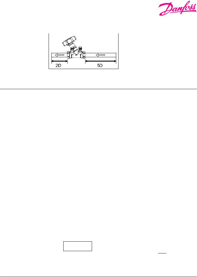
Installation: |
|
Install the balancing valve with the arrow on the |
|
||
|
|
valve’s body pointing in the direction of the flow |
|
|
in the system. |
To ensure an accurate reading, a straight length of 5 times the diameter of the pipe should be piped prior to the valve and a straight length of at least 2 times the pipe diameter should be piped after the valve.
If a pump is installed near the valve, a straight length of 10 times the diameter of the pipe should be piped prior to the valve to reduce an inaccurate measurement due to turbulence.
Setting Flow Coefficient values
(Cv value = gpm@1psi ∆P):
STV / |
|
|
|
|
Number of Turns |
|
|
|
|
|
|||
STVL |
|
|
|
|
|
|
|
|
|
||||
|
|
|
|
|
|
|
|
|
|
|
|
|
|
|
|
|
|
|
|
|
|
|
|
|
|
|
|
Size |
1 |
2 |
3 |
4 |
|
5 |
6 |
|
7 |
8 |
9 |
10 |
|
|
|
|
|
|
|
|
|
|
|
|
|
|
|
1/2” |
0.21 |
0.37 |
0.52 |
0.72 |
|
1.00 |
1.36 |
|
1.88 |
2.96 |
3.65 |
4.12 |
|
|
|
|
|
|
|
|
|
|
|
|
|
|
|
3/4” |
0.39 |
0.70 |
0.96 |
1.31 |
|
1.80 |
2.44 |
|
3.36 |
4.47 |
5.22 |
5.92 |
<![if ! IE]> <![endif]>Cv |
|
|
|
|
|
|
|
|
|
|
|
|
|
|
1” |
0.56 |
0.89 |
1.19 |
1.74 |
|
2.67 |
4.18 |
|
5.80 |
7.54 |
9.16 |
10.20 |
|
|
|
<![if ! IE]> <![endif]>Values |
|||||||||||
|
|
|
|
|
|
|
|
|
|
|
|
|
|
1-1/4” |
0.92 |
1.53 |
2.09 |
3.13 |
|
4.76 |
6.84 |
|
9.05 |
11.30 |
13.30 |
15.20 |
|
|
|
|
|||||||||||
|
|
|
|
|
|
|
|
|
|
|
|
|
|
1-1/2” |
1.39 |
2.38 |
3.25 |
4.76 |
|
7.19 |
10.3 |
|
13.90 |
17.10 |
19.80 |
22.60 |
|
|
|
|
|
|
|
|
|
|
|
|
|
|
|
2” |
2.32 |
4.18 |
6.03 |
8.82 |
|
13.80 |
19.4 |
|
24.60 |
29.00 |
33.20 |
36.50 |
|
|
|
|
|
|
|
|
|
|
|
|
|
|
|
STVA |
|
|
|
|
Number of Turns |
|
|
|
|
|
|||
|
|
|
|
|
|
|
|
|
|
|
|
|
|
Size |
1 |
2 |
3 |
4 |
|
5 |
6 |
|
7 |
8 |
9 |
10 |
|
|
|
|
|
|
|
|
|
|
|
|
|
|
|
2-1/2” |
3.2 |
5.9 |
11.1 |
23.2 |
|
41.2 |
59.2 |
|
76.6 |
91.1 |
101.0 |
108.0 |
|
|
|
|
|
|
|
|
|
|
|
|
|
|
<![if ! IE]> <![endif]>Cv |
3” |
6.4 |
11.0 |
15.7 |
21.5 |
|
34.2 |
56.8 |
|
79.5 |
98.6 |
114.0 |
128.0 |
|
4” |
9.3 |
15.7 |
22.0 |
38.3 |
|
77.7 |
115.0 |
|
145.0 |
174.0 |
197.0 |
220.0 |
<![if ! IE]> <![endif]>Values |
|
|
|
|||||||||||
|
|
|
|
|
|
|
|
|
|
|
|
|
|
5” |
11.6 |
25.5 |
38.3 |
73.1 |
|
123.0 |
174.0 |
|
225.0 |
274.0 |
317.0 |
349.0 |
|
|
|
|
|
|
|
|
|
|
|
|
|
|
|
6” |
20.9 |
38.3 |
78.9 |
151.0 |
|
216.0 |
285.0 |
|
341.0 |
394.0 |
447.0 |
493.0 |
|
|
|
|
|
|
|
|
|
|
|
|
|
|
|
STVC |
|
|
|
|
|
Number of Turns |
|
|
|
|
|
|
|||
|
|
|
|
|
|
|
|
|
|
|
|
|
|
|
|
Size |
2 |
3 |
4 |
5 |
6 |
7 |
8 |
9 |
10 |
11 |
12 |
14 |
16 |
18 |
|
|
|
|
|
|
|
|
|
|
|
|
|
|
|
|
|
8” |
46 |
66 |
84 |
139 |
215 |
290 |
365 |
452 |
545 |
638 |
696 |
- |
- |
- |
<![if ! IE]> <![endif]>Cv |
|
|
|
|
|
|
|
|
|
|
|
|
|
|
|
|
10” |
116 |
160 |
204 |
349 |
494 |
689 |
884 |
1031 |
1177 |
1291 |
1405 |
- |
- |
- |
<![if ! IE]> <![endif]>Values |
|
|||||||||||||||
|
|
|
|
|
|
|
|
|
|
|
|
|
|
|
|
12” |
116 |
180 |
244 |
396 |
546 |
708 |
869 |
1012 |
1153 |
1290 |
1427 |
1588 |
1668 |
1764 |
|
|
|
|
|
|
|
|
|
|
|
|
|
|
|
|
|
Based upon the flow or differential pressures required within the system, the flow can be determined by using the equation:
_____
Q = Cv . √∆p
Q = flow
Cv = flow coefficient ∆p = differential pressure
For correction of fluids other than water, the following equation applies provided the viscosity of the fluid is the same for water, which is the case for most glycol and brine solutions:
Q R = |
Q M |
√ |
|
|
___ |
|
|
Q R = real flow
Q M = measured flow
= specific density of fluid
VDDNB122 © Danfoss 05/08 |
3 |
 Loading...