


Danfoss How to design balancing and control solutions for energy efficient hydronic applications in residential and commercial buildings Application guide

Application guide
How to design
balancing and control solutions for energy efficient hydronic applications in residential and commercial buildings
44
applications with detailed descriptions about the investment, design, construction and control
hbc.danfoss.com
Content structure in this guide
1. Hydronic applications |
2. Mixing loop |
|
1.1 Commercial |
3. AHU applications |
|
1.1.1 Variable flow |
||
3.1 AHU applications heating |
||
1.1.2 Constant flow |
||
3.2 AHU applications cooling |
||
1.2 Residential |
||
4. Chillers applications |
||
1.2.1 Two-pipe system |
||
5. Boiler applications |
||
1.2.2 One-pipe system |
||
1.2.3 Heating – special application |
6. Hot water applications |
|
|
Typical page shows you:
Recommendation
Chapter
Schematic drawing
Application
General system description
Danfoss products
Performance indicators 
Application details
7.Glossary and abbreviations
8.Control and valve theory
9.Energy efficiency analyses
10.Product overview
Type of solution
2

Introduction |
Notes |
Designing HVAC systems is not that simple. Many factors need to be considered before making the final decision about the heatand/or cooling load, which terminal units to use, how to generate heating or cooling and a hundred other things.
This application guide is developed to help you make some of these decisions by showing the consequences of certain choices. For example, it could be tempting to go for the lowest initial cost (CAPEX) but often there would be compromises on other factors, like the energy consumption or the Indoor Air Quality (IAQ). In some projects the CAPEX might be the deciding factor but in another ones it is more about energy efficiency or control precision, therefore it differs from project to project. We collected the most important information concerning a particular solution on a single page with clear indications what consequences can be expected when certain choices are made.
The aim of this guide was not to cover each and every application because that would be impossible. Every day, smart designers come up with new solutions that might be relevant only to one specific problem or that is solving new problems.That is what engineers do. The drive for greener, more energy-friendly solutions is creating new challenges every day, so there are always some new applications. In this particular guide we will find to cover the applications that are the most common.
Danfoss also has many competent people available that can support you with specific challenges or that can support you with calculations. Please contact your local Danfoss office for support in your native language.
We hope this guide will help you in your daily work.
Each application shown here is analyzed for four aspects:
Return on Investment, Design, Operation/Maintenance, Control
Return of investment |
|
|
Operation/Maintenance |
|
||
|
|
|
|
|
|
|
|
|
|
|
|
|
|
poor |
acceptable |
exellent |
|
poor |
acceptable |
exellent |
Design |
|
|
|
Control |
|
|
|
|
|
|
|
|
|
|
|
|
|
|
|
|
poor |
acceptable |
exellent |
|
poor |
acceptable |
exellent |
All of them are marked as:
Technically and economically optimized solutions as recommended by Danfoss.
This solution will result in efficiently operating systems.
 Recommended
Depending on the situation and the particularities of the system this will result in a good installation. However, some trade-offs are made.
Acceptable
This system is not recommended since it will result in expensive and inefficient systems or the Indoor Air Quality is not ensured.
 Not Recommended
3
Table of Contents
Content structure in this guide |
2 |
Typical page shows you: |
2 |
Introduction |
3 |
1. Hydronic applications |
|
1.1Hydronic applications – commercial buildings |
6 |
1.1.1 Commercial - Variable flow |
|
1.1.1.1 Variable flow: Pressure Independent Control (PICV) with ON/OFF actuator |
8 |
1.1.1.2 Variable flow: Pressure Independent Control (PICV) with proportional control |
9 |
1.1.1.3 Variable flow: Pressure Independent Control (PICV) with digital actuator |
10 |
1.1.1.4 Variable flow: Flow limitation (with flow limiter) on terminal unit with ON/OFF or modular actuator |
11 |
1.1.1.5 Variable flow: Differential pressure control with ON/OFF or modulation |
12 |
1.1.1.6 Variable flow: Shell and Core installation for Offices and Shopping malls* |
13 |
1.1.1.7 Variable flow: Manual balancing |
14 |
1.1.1.8 Variable flow: Manual balancing with reverse return |
15 |
1.1.1.9 Variable flow: Four-pipe Changeover (CO6) for radiant heating/cooling panels, |
|
chilled beams, etc. with PICV control valve |
16 |
1.1.1.10 Variable flow: Two-pipe heating/cooling system with central changeover* |
17 |
1.1.2 Commercial - Constant flow |
|
1.1.2.1 Constant flow: 3-way valve with manual balancing (in fan-coil, chilled beam etc. application) |
18 |
1.1.2.2 Constant flow: 3-way valve with flow limiter on terminal units (fan-coil, chilled beam etc. application) |
19 |
1.2 Hydronic applications - residential buildings |
|
1.2.1 Residential - Two pipes system |
|
1.2.1.1 Two-pipe radiator heating system – risers with, thermostatic radiator valves (with presetting) |
20 |
1.2.1.2 Two pipe radiator heating system – risers with, thermostatic radiator valves (without presetting) |
21 |
1.2.1.3 Pressure Independent Control for radiator heating system |
22 |
1.2.1.4 Subordinated risers (staircase, bathroom, etc.) in twoor one-pipe radiator heating system without thermostatic valve 23
1.2.1.5 Δp control for manifold with individual zone/loop control |
24 |
1.2.1.6 Δp control and flow limitation for manifold with central zone control |
25 |
1.2.2 Residential - One pipe system |
|
1.2.2.1 One-pipe radiator heating system renovation with automatic flow limitation |
|
and possible self-acting return temperature limitation |
26 |
1.2.2.2 One-pipe radiator heating system renovation with electronic flow limitation and return temperature control |
27 |
1.2.2.3 One-pipe radiator heating system renovation with manual balancing |
28 |
1.2.2.4 One-pipe horizontal heating systems with thermostatic radiator valves, flow limitation |
|
and return temperature self-acting control |
29 |
1.2.3 Residential - Heating - special application |
|
1.2.3.1 Three-pipe, flat station system; Δp controlled heating and local DHW* preparation |
30 |
2. Mixing loop
2.1 |
Mixing with PICV – manifold with pressure difference |
31 |
2.2 |
Injection (constant flow) control with 3-way valve |
32 |
2.3 |
Mixing with 3-way valve – manifold without pressure difference |
33 |
3 AHU applications |
|
|
3.1 AHU applications - heating |
|
|
3.1.1 Pressure Independent Control (PICV) for cooling |
34 |
|
3.1.2 3-way valve control for cooling |
35 |
|
3.2 AHU applications - cooling |
|
|
3.2.1 Pressure Independent Control (PICV) for heating |
36 |
|
3.2.2 3-way valve control for heating |
37 |
|
3.2.3 Keep proper flow temperature in front of AHU in partial load condition |
38 |
|
4. Chillers applications |
|
|
4.1 |
Variable primary flow |
39 |
4.2 |
Constant primary variable secondary (Step Primary) |
40 |
4.3 |
Constant primary and variable secondary (Primary Secondary) |
41 |
4.4 |
Constant primary & secondary (Constant Flow System) |
42 |
4.5 |
District cooling system |
43 |
5. Boiler applications |
|
|
5.1 |
Condensing boiler, variable primary flow |
44 |
5.2 |
Traditional boilers, variable primary flow |
45 |
5.3 |
System with manifolds de-couplers |
46 |
6. Domestic hot water |
|
|
6.1 |
Thermal balancing in DHW circulation (vertical arrangement) |
47 |
6.2 |
Thermal balancing in DHW circulation (horizontal loop) |
48 |
6.3 |
Thermal balancing in DHW circulation with self–acting disinfection |
49 |
6.4 |
Thermal balancing in DHW circulation with electronic desinfection |
50 |
6.5 |
DHW* circulation control with manual balancing |
51 |
7. Glossary and abbreviations |
54 |
|
8. Control and valve theory |
56 |
|
9. Energy efficiency analyses |
65 |
|
10. Product overview |
75 |
|
| <![if ! IE]> <![endif]>Hydronic applications |
<![if ! IE]> <![endif]>Commercial |
|
|
| <![if ! IE]> <![endif]>Hydronic applications |
<![if ! IE]> <![endif]>Residential |
<![endif]>Mixing loop
<![if ! IE]><![endif]>AHU heating
<![if ! IE]><![endif]>AHU application
<![if ! IE]><![endif]>AHU cooling
<![if ! IE]><![endif]>AHU application
<![if ! IE]><![endif]>Boilers applications Chillers applications
<![if ! IE]><![endif]>Hot water
Hydronic applications – commercial buildings |
Notes |
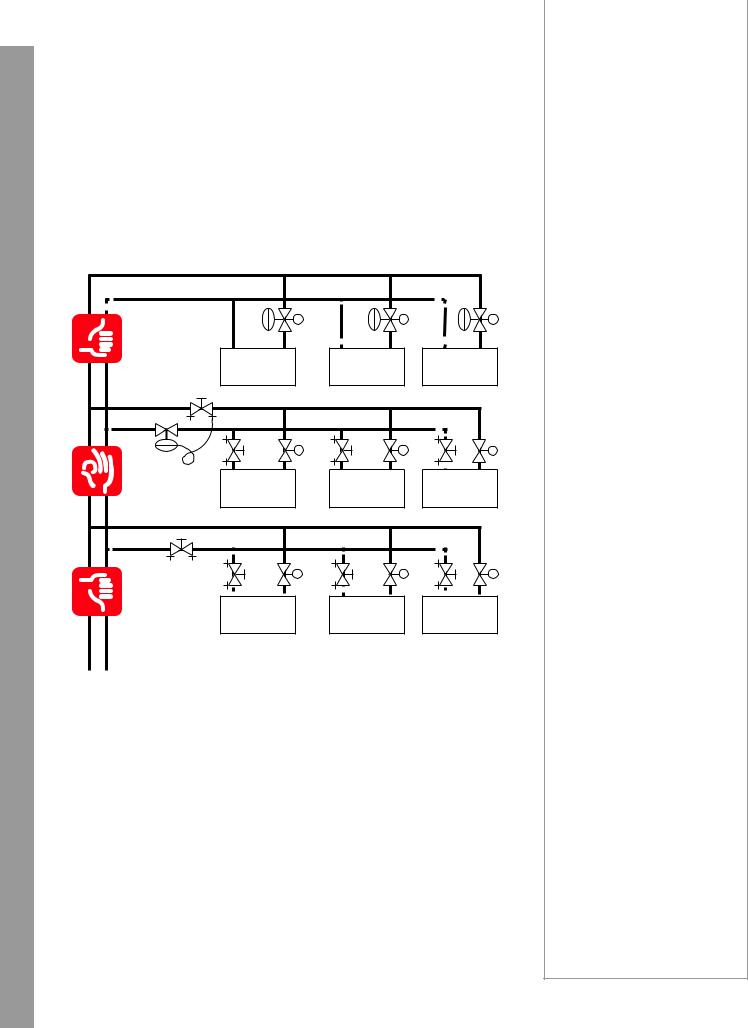
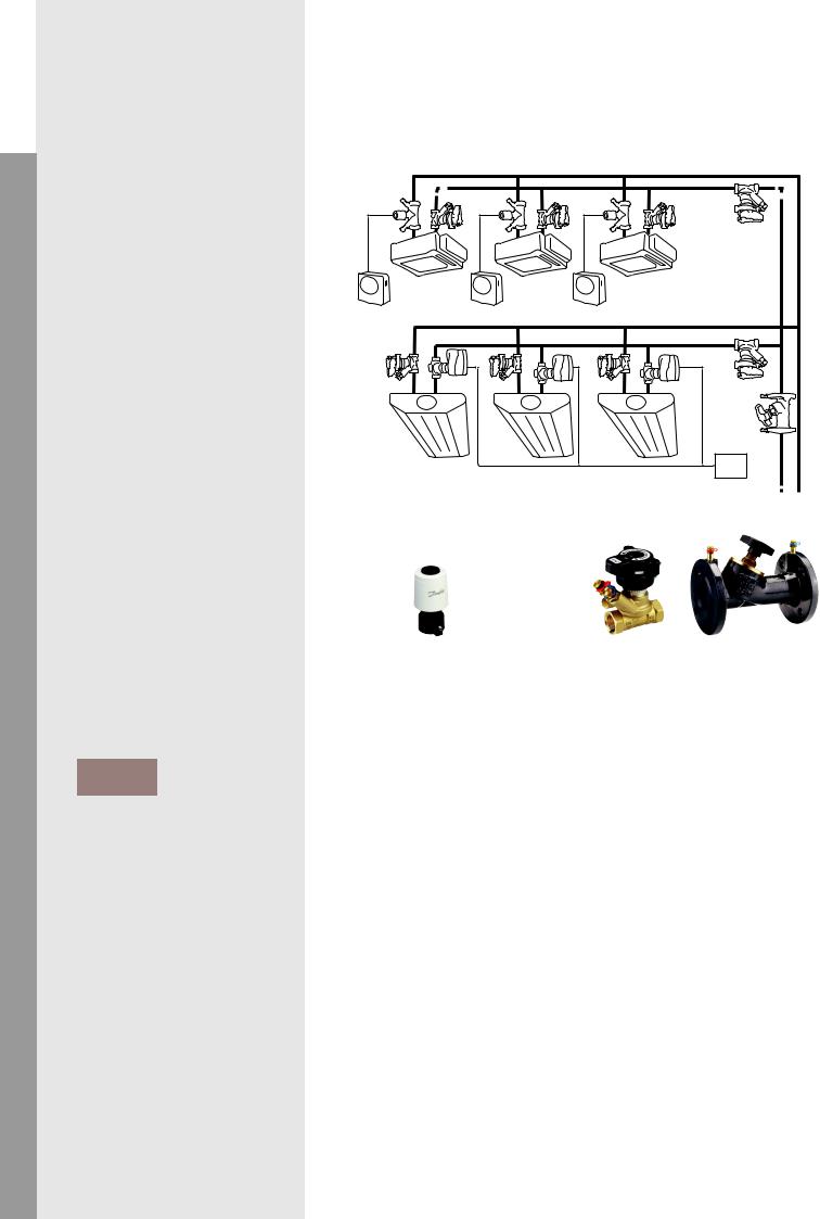
Variable flow* systems |
|
|
1.1.1.1 - 1.1.1.6**
Hydronic applications can be controlled and balanced based on a lot of different type of solutions. It is impossible to find the best one for all.
We have to take into consideration each system and its specific to decide what kind of solution will be the most efficient and suitable.
All applications with control valves are variable flow* systems. Calculation is generally done based on nominal parameters but during operation flow in each part of the system is changing (control valves are working). Flow changes result in pressure changes. That’s why in such case we have to use balancing solution that allows to respond to changes in partial load.
Pressure |
Independent |
Control |
Di erential |
Pressure |
Control |
Manual |
Balancing |
The evaluation of systems (Recommended/Acceptable/Not recommended) is principally based on combination of 4 aspects mentioned on page 3 (Return on investment/Design/ Operation-Maintenance/Control) but the most important factors are the system performance and efficiency.
On application above the manual balanced system is Not recommended because the static elements are not able to follow the dynamic behaviour of variable flow* system and during partial load condition huge overflow occurs on control valves (due to smaller pressure drop on pipe network).
The differential pressure controlled system performs much better (Acceptable) because the pressure stabilization is closer to control valves and although we still have manual balanced system inside the dp controlled loop, the overflow phenomenon mitigated. The efficiency of such system depends on location of differential pressure control valve. The closer it is to control valve, the better it works.
The most efficient (Recommended) system we can have is using PICV (pressure independent control valves). In this case the pressure stabilization is right on the control valve, therefore we have full authority* and we are able to eliminate all unnecessary flow from the system.
6 |
*see page 54-55 |
** applications below |
Hydronic applications – commercial buildings |
Notes |
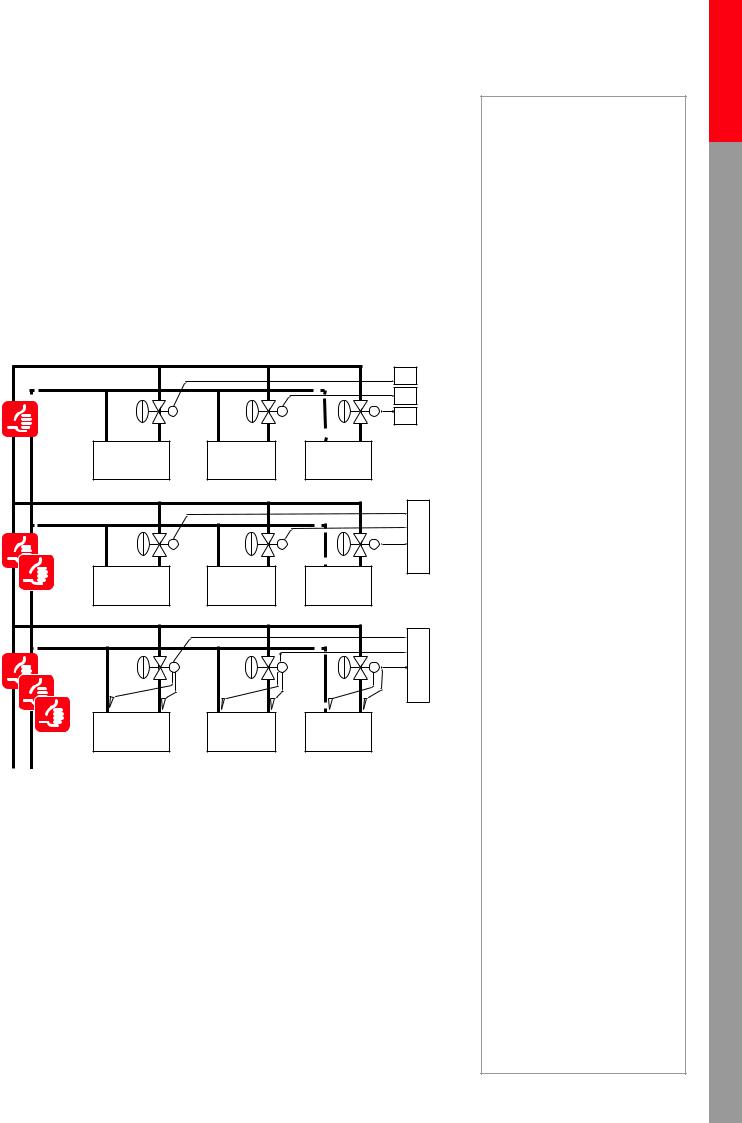
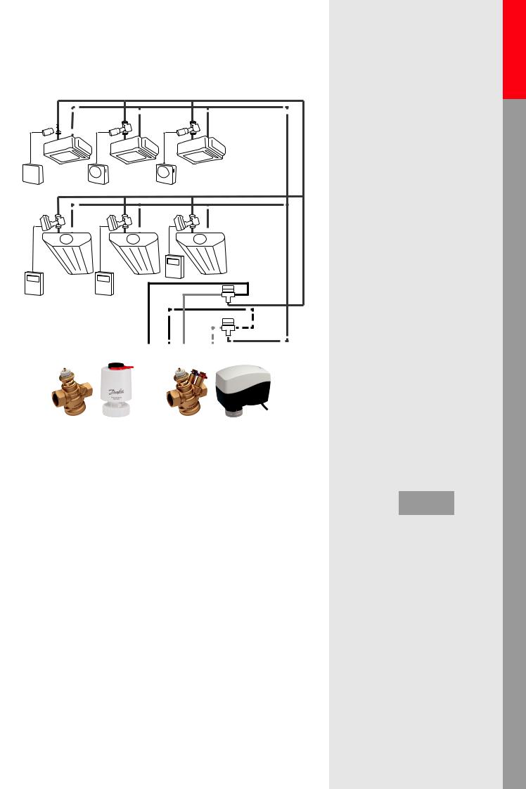
Variable flow* system: PICV – ON/OFF vs modulating vs smart control
1.1.1.1 - 1.1.1.3**
All these applications base on PICV (Pressure Independent Control Valve) technology. It means the control valve (integrated into the valve body) is independent from pressure fluctuation in the system during both full, and partial load conditions. This solution allows us to use different types of actuators (control method)
•With ON/OFF control, the actuator has two positions, open and closed
•With modulation control the actuator is able to set any flow between nominal and zero value
•With SMART actuator we can ensure (above modulation control) direct connectivity to BMS (Building Management System) to use advanced functions such as energy allocation, energy management etc.
|
<![if ! IE]> <![endif]>ON/OFF |
|
|
|
<![if ! IE]> <![endif]>Controlers |
|
|
<![if ! IE]> <![endif]>PICV & |
|
|
|
|
|
|
<![if ! IE]> <![endif]>PICV & modulating |
|
|
|
<![if ! IE]> <![endif]>Controler |
|
T |
T |
<![if ! IE]> <![endif]>actuator |
T |
T |
T |
T |
|
|
|
|
|
<![if ! IE]> <![endif]>Controler |
|
|
<![if ! IE]> <![endif]>PICV & SMART |
|
|
|
|
|
PICV technology allows us to use proportional or end point (based on Δp sensor) pump control
The above mentioned control types strongly affect on overall energy consumption of systems.
While ON/OFF control ensures either 100% or 0 flow during operation, the modulation control enables to minimize the flow rate through on terminal unit according real demand. For example, to the same 50% average energy demand we need around 1/3 of flow rate to modulation control, compared to ON/OFF control. (You can find more details in chapter 9) The lower flow rate contributes to energy saving* on more levels:
•Less circulation cost (fewer flow needs less electricity)
•Improved chiller/boiler efficiency (less flow ensures bigger ΔT in the system)
•Smaller room temperature oscillation* ensures better comfort and defines the room temperature setpoint
The SMART control – over the above mentioned benefits - enable to reduce the maintenance cost with remote access and predictive maintenance.
<![endif]>applications Hydronic applications Hydronic
<![if ! IE]><![endif]>Residential Commercial
<![if ! IE]><![endif]>loop Mixing
<![if ! IE]><![endif]>application AHU
<![if ! IE]><![endif]>heating AHU
<![if ! IE]><![endif]>application AHU
<![if ! IE]><![endif]>cooling AHU
<![if ! IE]><![endif]>applications Boilers applications Chillers
<![if ! IE]><![endif]>water Hot
*see page 54-55 |
7 |
** applications below |
| <![if ! IE]> <![endif]>Hydronic applications |
<![if ! IE]> <![endif]>Commercial |
|
|
| <![if ! IE]> <![endif]>Hydronic applications |
<![if ! IE]> <![endif]>Residential |
<![endif]>Mixing loop
<![if ! IE]><![endif]>AHU cooling
<![if ! IE]><![endif]>AHU applications
<![if ! IE]><![endif]>Boilers applications Chillers applications AHU heating
<![if ! IE]><![endif]>AHU applications
<![if ! IE]><![endif]>Hot water
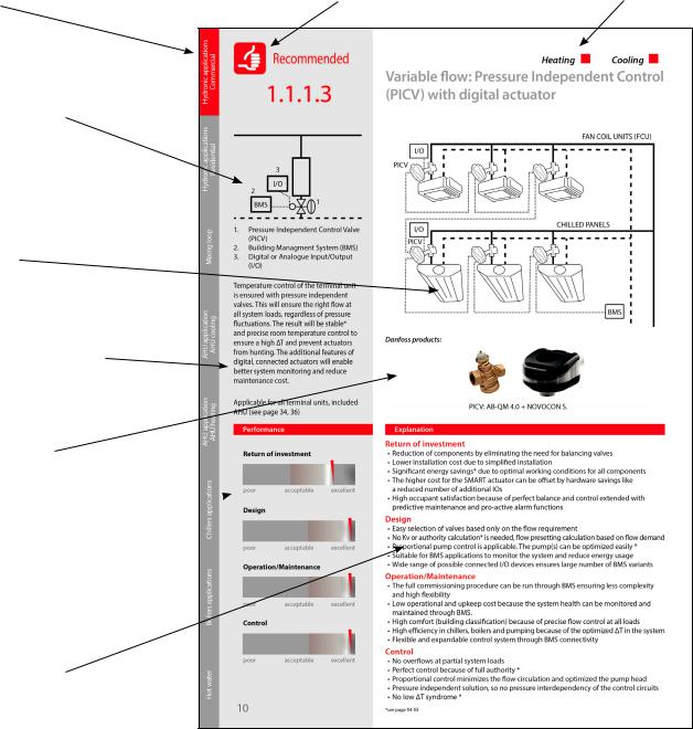
Recommended |
Heating |
Cooling |
1.1.1.1 |
Variable flow: Pressure Independent Control |
|
(PICV) with ON/OFF actuator |
|
|
2
1
1.Preasure Independent Control Valve (PICV)
2.Room temperature Control (RC)
Balancing of the terminal unit by pressure independent valves. This will ensure the right flow at all system loads, regardless of pressure fluctuations. ON/OFF control will cause fluctuations in the room temperature. The system will not be operating optimally because the ΔT
is not optimized.
Performance
Return of investment
poor |
acceptable |
excellent |
Design
poor |
acceptable |
excellent |
Operation/Maintenance
poor |
acceptable |
excellent |
Control |
|
|
poor |
acceptable |
excellent |
FAN COIL UNITS (FCU)
PICV-1 |
RC |
CHILLED PANELS |
PICV-2 |
RC |
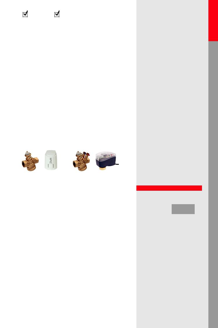
Danfoss products:
PICV-1: AB-QM 4.0 + TWA-Q |
PICV-2: AB-QM 4.0 + AMI-140 |
Explanation
Return of investment
•Reduction of components by eliminating the need for balancing valves
•Lower installation cost due to simplified installation
•The chillers and boilers operate efficiently but not optimally because the ∆T is not optimized
•Handover of the building can easily be done in phases
Design
•Easy selection of valves based only on the flow requirement
•No Kv or authority* calculation is needed, the calculation is based on flow demand
•Perfect balance at all loads
•Proportional pump control is applicable and the pump(s) can be optimized* easily
•Min available ∆p demand on the valve can be taken for calculating the pump head
Operation/Maintenance
•Simplified construction because of a reduction of components
•Set and forget, so no complicated balancing procedures
•Fluctuating room temperature, so some occupant complaints can be expected
•Low operational and upkeep cost, so occupants may experience discomfort
•Good but reduced efficiency in chillers, boilers and pumping because of a sub-optimized ∆T in the system
Control
•Temperature fluctuations *
•No overflows*
•Pressure independent solution, so no pressure changes do not affect control circuits
•Low ∆T syndrome* is unlikely to happen
8 |
*see page 54-55 |
Heating |
Cooling |
Variable flow: Pressure Independent Control (PICV) with proportional control
FAN COIL UNITS (FCU)
PICV-1 |
|
RC |
0-10V |
|
CHILLED PANELS |
PICV-2 |
|
|
BMS |
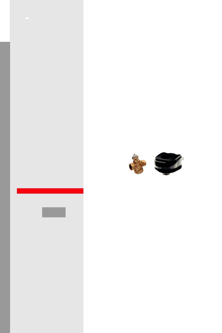
Danfoss products:
PICV-1: AB-QM 4.0 + ABNM A5 |
PICV-2: AB-QM 4.0 + AME 110 NL |
Recommended 
1.1.1.2
2
1
1.Pressure Independent Control Valve (PICV)
2.Building Management System (BMS) or Room temperature Control (RC)
Temperature control of the terminal unit is ensured with pressure independent valves. This will ensure the right flow at all system loads, regardless of pressure fluctuations. The result will be stable* and precise room temperature control to ensure a high ΔT and prevent actuators from hunting.
Applicable for all terminal units, included AHU (see page 34, 36)
Explanation
Return of investment
•Reduction of components by eliminating the need for balancing valves
•Lower installation cost due to simplified installation
•Significant energy savings* due to optimal working conditions for all components
•Handover of the building can easily be done in phases
Design
•Easy selection of valves based only on the flow requirement
•No Kv or authority* calculation is needed, flow presetting calculation based on flow demand
•Proportional pump control is applicable. The pump(s) can be optimized easily *
•Suitable for BMS applications to monitor the system and reduce energy usage
Performance
Return of investment
|
|
|
poor |
acceptable |
excellent |
Design
Operation/Maintenance |
poor |
acceptable |
excellent |
|
• Simplified construction because of a reduction of components |
Operation/Maintenance |
|
||
• Set and forget, so no complicated balancing procedures |
|
|||
• Good control at all loads, so no complaints by occupants |
|
|
|
|
|
|
|
||
• Low operational and upkeep cost |
|
|
|
|
• High comfort (building classification*) because of precise flow control at all loads |
|
|
|
|
• High efficiency in chillers, boilers and pumping because of the optimized ∆T in the |
poor |
acceptable |
excellent |
|
system |
|
|
|
|
Control |
Control |
|
|
|
• Perfect control because of full authority * |
|
|
|
|
|
|
|
||
• No overflows* at partial system loads |
|
|
|
|
• Proportional control minimizes the flow circulation and optimizes the pump head |
|
|
|
|
poor |
acceptable |
excellent |
||
• Pressure independent solution, so pressure interdependency of the control circuits |
||||
• No low ∆T syndrome * |
|
|
|
|
<![endif]>applications Hydronic applications Hydronic
<![if ! IE]><![endif]>Residential Commercial
<![if ! IE]><![endif]>loop Mixing
<![if ! IE]><![endif]>applications AHU
<![if ! IE]><![endif]>cooling AHU
<![if ! IE]><![endif]>applications Boilers applications Chillers applicationsheating AHUAHU
<![if ! IE]><![endif]>water Hot
*see page 54-55 |
9 |
| <![if ! IE]> <![endif]>Hydronic applications |
<![if ! IE]> <![endif]>Commercial |
|
|
| <![if ! IE]> <![endif]>Hydronic applications |
<![if ! IE]> <![endif]>Residential |
<![endif]>Mixing loop
<![if ! IE]><![endif]>AHU cooling
<![if ! IE]><![endif]>AHU applications
<![if ! IE]><![endif]>Boilers applications Chillers applications AHU heating
<![if ! IE]><![endif]>AHU applications
<![if ! IE]><![endif]>Hot water
 Recommended
1.1.1.3
3
I/O
2
BMS 


 1
1
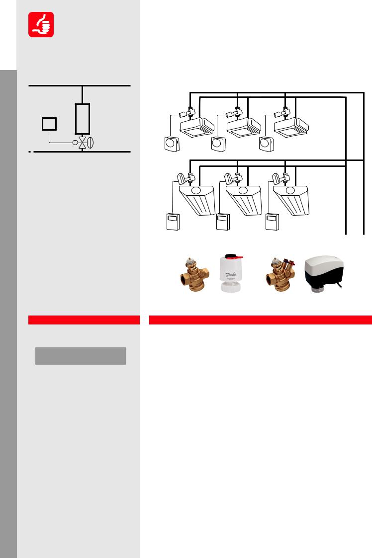
1.Pressure Independent Control Valve (PICV)
2.Building Management System (BMS)
3.Digital or Analogue Input/Output (I/O)
Temperature control of the terminal unit is ensured with pressure independent valves. This will ensure the right flow at all system loads, regardless of pressure fluctuations. The result will be stable and precise room temperature control to ensure a high ΔT and prevent actuators from hunting. The additional features of digital, connected actuators will enable better system monitoring and reduce maintenance cost.
Applicable for all terminal units, included AHU (see page 34, 36)
Heating |
Cooling |
Variable flow: Pressure Independent Control (PICV) with digital actuator
FAN COIL UNITS (FCU)
I/O |
|
PICV |
|
I/O |
CHILLED PANELS |
|
|
PICV |
|
|
BMS |
Danfoss products:
PICV: AB-QM 4.0 + NovoCon® S.
Performance Explanation
|
|
|
Return of investment |
|
Return of investment |
|
• Reduction of components by eliminating the need for balancing valves |
||
|
|
|
• Lower installation cost due to simplified installation |
|
|
|
|
• Significant energy savings* due to optimal working conditions for all components |
|
|
|
|
• The higher cost for the SMART actuator can be offset by hardware savings like |
|
poor |
acceptable |
excellent |
a reduced number of additional IOs |
|
|
|
|
• High occupant satisfaction because of perfect balance and control extended with |
|
Design |
|
|
predictive maintenance and pro-active alarm functions |
|
|
|
Design |
||
|
|
|
||
|
|
|
||
|
|
|
• Easy selection of valves based only on the flow requirement |
|
|
|
|
• No Kv or authority calculation* is needed, flow presetting calculation based on flow demand |
|
poor |
acceptable |
excellent |
• Proportional pump control is applicable. The pump(s) can be optimized easily * |
|
|
|
|
• Suitable for BMS applications to monitor the system and reduce energy usage |
|
Operation/Maintenance |
|
• Wide range of possible connected I/O devices ensures large number of BMS variants |
||
|
|
|||
|
|
|
Operation/Maintenance |
|
|
|
|
||
|
|
|
• The full commissioning procedure can be run through BMS ensuring less complexity |
|
|
|
|
and high flexibility |
|
poor |
acceptable |
excellent |
• Low operational and upkeep cost because the system health can be monitored and |
|
|
|
|
maintained through BMS. |
|
Control |
|
|
• High comfort (building classification) because of precise flow control at all loads |
|
|
|
|
• High efficiency in chillers, boilers and pumping because of the optimized ∆T in the system |
|
|
|
|
• Flexible and expandable control system through BMS connectivity |
|
|
|
|
Control |
|
poor |
acceptable |
excellent |
||
• No overflows at partial system loads |
||||
|
|
|
• Perfect control because of full authority * |
|
• Proportional control minimizes the flow circulation and optimizes the pump head
• Pressure independent solution, so pressure changes do not affect control circuits
• No low ∆T syndrome *
10 |
*see page 54-55 |
Heating |
Cooling |
Variable flow: Flow limitation (with flow limiter) on terminal unit with ON/OFF or modular actuator
FAN COIL UNITS (FCU)
CV-1 |
|
ON/OFF |
FL |
|
|
RC |
|
CV-2 |
CHILLED PANELS |
|
|
0-10V |
FL |
|
|
|
BMS |
Danfoss products:
CV-1: RA-HC + TWA-A |
CV-2: VZ2 + AME130 |
FL: AB-QM |
Explanation
Return of investment
•Relatively high product cost because of 2 valves for all terminal units (one CV + FL)
•Higher installation costs although no manual partner valves* are needed
•Variable speed pump is recommended (proportional pump control is possible)
Design
•Traditional calculation is needed but only the kvs of the control valve. It is not necessary to calculate the authority* since the FL will take away the authority of the CV
•For ON/OFF control it is an acceptable solution (simple design: big kvs of zone valve, flow limiter selected based on flow demand)
•High pump head is needed because of the two valves (additional Δp on flow limiter)
Operation/Maintenance
•Closing force of actuator should be able to close the valve against the pump head at minimum flow
•Most flow limiters have pre-determined flow, no adjustment is possible.
•For flushing cartridges need to be removed from the system and placed back afterwards (emptying and filling the system twice)
•Cartridges have small openings and clog easily
•If modulation is attempted the lifetime of the CV is very short due to hunting at partial system loads
•High energy consumption with modulation control due to higher pump head and overflow on terminal units in partial load
Control
•Temperature fluctuations due to ON/OFF control, even with modulating actuators*
•No overflows*
•No pressure interdependency of the control circuits
•Overflow during partial load when modulating because the FL will keep the maximum flow if possible
Not Recommended 
1.1.1.4
2 

3
1
1.2-way Control Valve (CV)
2.Flow Limiter (FL)
3.Building Management System (BMS) or Room temperature Control (RC)
Temperature control of the terminal unit is done by conventional motorized control valves (CV) while the hydronic balance in the system is realized by automatic flow limiter (FL). For ON/OFF control this could be an acceptable solution, provided that the pump head is not too high. For modulating control this is not acceptable. The FL will counteract the actions of the CV and fully distort the control characteristic. Therefore, modulation with this solutions is impossible.
Performance
Return of investment
|
|
|
poor |
acceptable |
excellent |
Design
|
|
|
poor |
acceptable |
excellent |
Operation/Maintenance
|
|
|
poor |
acceptable |
excellent |
Control |
|
|
|
|
|
|
|
|
poor |
acceptable |
excellent |
3-point or pro- |
ON/OFF |
|
portional control |
control |
|
<![endif]>applications Hydronic applications Hydronic
<![if ! IE]><![endif]>Residential Commercial
<![if ! IE]><![endif]>loop Mixing
<![if ! IE]><![endif]>applications AHU
<![if ! IE]><![endif]>cooling AHU
<![if ! IE]><![endif]>applications Boilers applications Chillers applicationsheating AHUAHU
<![if ! IE]><![endif]>water Hot
*see page 54-55 |
11 |
| <![if ! IE]> <![endif]>Hydronic applications |
<![if ! IE]> <![endif]>Commercial |
|
|
| <![if ! IE]> <![endif]>Hydronic applications |
<![if ! IE]> <![endif]>Residential |
<![endif]>Mixing loop
<![if ! IE]><![endif]>AHU cooling
<![if ! IE]><![endif]>AHU applications
<![if ! IE]><![endif]>Boilers applications Chillers applications AHU heating
<![if ! IE]><![endif]>AHU applications
<![if ! IE]><![endif]>Hot water
 Acceptable
1.1.1.5
5 |
1 |
2 |
|
|
|
|
6 |
6 |
|
4 |
3 |
1.Zone Control Valve (with presetting) (CV)
2.Zone Control Valve (no presetting) (CV)
3.Manual Balancing Valve (MBV)
4.Δp Controller (DPCV)
5.Partner Valve*
6.Building Management System (BMS) or Room temperature Control (RC)
Temperature control at the terminal unit is done by conventional motorized control valve (CV). Hydronic balance is achieved by differential pressure controllers (DPCV) on the branches and manual balancing valves (MBV) at the terminal unit. If the CV has a pre-setting option the MBV is redundant.
It guarantees that, regardless of pressure oscillations in the distribution network, we have the right pressure and flow in the pressure-controlled segment.
Performance
Return of investment
|
|
|
poor |
acceptable |
excellent |
Design
|
|
|
poor |
acceptable |
excellent |
Operation/Maintenance
|
|
|
poor |
acceptable |
excellent |
Control |
|
|
|
|
|
|
|
|
poor |
acceptable |
excellent |
3-point or pro- |
ON/OFF |
|
portional control |
control |
|
Heating |
Cooling |
Variable flow: Differential pressure control with ON/OFF or modulation
FAN COIL UNITS (FCU)
CV-1 |
|
ON/OFF |
DPCV |
|
|
RC |
|
CV-2 |
CHILLED PANELS |
|
|
0-10V |
MBV |
|
|
|
DPCV |
|
BMS |
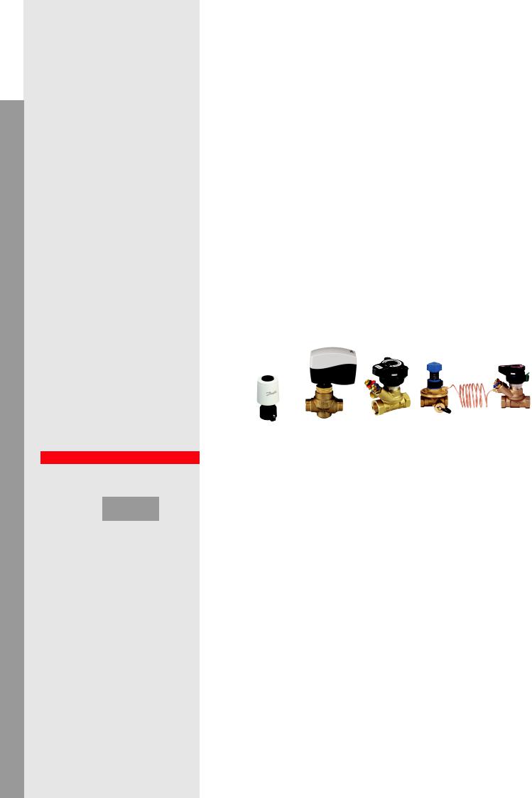
Danfoss products:
CV-1: RA-HC +TWA-A CV-2: VZ2 + AME130 MBV: MSV-BD |
DPCV: ASV-PV+ASV-BD |
Explanation
Return of investment
•Requires Δp controllers and partner valves*.
•MBVs or pre-settable CV is needed for each terminal unit
•Cooling systems might require big and expensive (flanged) Δp controllers
•Good energy efficiency because there are only limited overflows* in partial load
Design
•Simplified design because the branches are pressure independent
•Kv calculation needed for Δp controller and control valve. An authority* calculation is also needed for modulating control
•Pre-setting calculation for terminal units is necessary for proper water distribution within the branch
•The setting for the Δp controller needs to be calculated
•A variable speed pump is recommended
Operation/Maintenance
•More components to install included impulse tube connection between Δp - and partner valve*
•Simplified commissioning* procedure because of pressure independent branches
•Balancing on the terminal units is still required although simplified by Δp controlled branch
•Phased commissioning is possible (branch by branch)
Control
•Generally acceptable to good controllability
•Pressure fluctuations that impact the controllability can occur with long branchesor and/or big Δp on terminal units
•Depending on the size of the branch overflows can still result in room temperature fluctuations.
•If we use flow limitation on partner valve* connected to Δp controller (not on terminal units), higher overflow and room temperature oscillation* are expected
12 |
*see page 54-55 |
Heating |
Cooling |
Variable flow: Shell and Core installation for Offices and Shopping malls*
FAN COIL UNITS (FCU)
PICV-3 |
PICV-1 |
PICV-3 |
|
? |
RC |
|
VACANT |
|
|
|
CHILLED PANELS |
|
PICV-3 |
PICV-1 |
|
|
|
|
PICV-2 |
|
|
|
VACANT |
|
|
BMS |
Danfoss products:
PICV-1: AB-PM+AME435QM |
PICV-2 & PICV3: AB-PM + TWA-Q |
Explanation
Return of investment
•Only one valve needed
•One actuator for zone or flow control
•Variable speed pump is recommended (proportional pump control is possible)
Design
•No kvs and authority* calculation needed.
•Presetting calculation needed only based on flow and Δp demand of loop
•For loop design (later stage of installation) the set parameters are available
Operation/Maintenance
•Reliable solution for shop or floor connection
•Flow setting can be done based on measurements on the test plugs of the valve
•Central distribution is always correctly balanced and independent of any mistakes made in sizing on the occupant‚s side
•Changes in secondary section of the system do not influence other shops or floors
•Easy trouble shooting, energy allocation, management, etc. with NovoCon
Control
•Stable pressure difference for shops or floors
•If only flow limitation is used small overflows can happen within the loop during partial load
•Actuator on valve (if applied) ensures either zone control (Δp control application) or flow control (flow control application)
**Two different approaches can be chosen:
1.Flow and ΔP limitation. Here the valve limits both the ΔP and the flow.
2.Flow limitation only. This will require additional zone controls and balancing for the terminal units
|
1.1.1.6 |
|
<![if ! IE]> <![endif]>applicationsHydronic Commercial |
|
Recommended |
|
|
1 |
2 |
|
<![if ! IE]> <![endif]>applicationsHydronic Residential |
|
? |
? |
|
|
|
1. |
Combined Automatic Balancing |
<![if ! IE]> <![endif]>Mixing |
|
Valve as Δp Controller (PICV 1) |
|
|
|
|
2. |
Combined Automatic Balancing |
<![if ! IE]> <![endif]>loop |
|
Valve as Flow Controller (PICV 2) |
|
|
|
This application is useful specifically for |
|
||||
situations where the system is built in two |
<![if ! IE]> <![endif]>applications AHU cooling AHU |
||||
phases by different contractors. The first |
|||||
phase is usually the central infrastructure, |
|||||
like boilers, chillers and transport piping, |
|||||
while the second part includes the termi- |
|||||
nal units and room controls. |
|||||
|
|
|
|
|
|
This commonly occurs in shopping malls, |
|
||||
where the shops use their own contractor |
|
||||
to do the shop’s installation, or Shell & |
|
||||
Core offices where the renter of an office |
<![if ! IE]> <![endif]>applications AHU heating AHU |
||||
floor fits out his own space, including the |
|||||
HVAC. |
|
|
|
||
|
|
|
|
|
|
Performance |
|
|
|
||
|
Return of investment |
|
|
||
|
|
|
|
||
|
|
|
|
<![if ! IE]> <![endif]>Chillers |
|
|
|
|
|
|
|
|
poor |
acceptable |
excellent |
||
|
|
|
|
|
|
|
Design |
|
|
|
<![if ! IE]> <![endif]>applications |
|
|
|
|
|
|
|
|
|
|
|
|
|
poor |
acceptable |
excellent |
|
|
|
Operation/Maintenance |
<![if ! IE]> <![endif]>Boilers |
|||
|
|
|
|
|
|
|
|
|
|
|
|
|
|
|
|
|
<![if ! IE]> <![endif]>applications |
|
poor |
acceptable |
excellent |
||
|
Control |
|
|
|
|
|
|
|
|
|
|
|
|
|
|
|
|
|
poor |
acceptable |
excellent |
|
|
|
p control |
|
Flow control |
<![if ! IE]> <![endif]>Hot |
|
|
application |
|
application |
||
|
|
<![if ! IE]> <![endif]>water |
|||
|
|
|
|
|
|
*see page 54-55 |
13 |
| <![if ! IE]> <![endif]>applicationsHydronic Commercial |
|
|
1.1.1.7 |
|
|
||||||||||||||||||||||
|
|
|
|
|
|
|
|
|
|
|
|
|
|
|
|
Not Recomended |
|||||||||||
|
|
|
|
|
|
|
|
|
|
|
|
|
|
|
|
|
|
|
|
|
|
|
|
|
|
|
|
| <![if ! IE]> <![endif]>applicationsHydronic Residential |
|
|
|
|
|
|
|
|
|
|
|
|
|
|
|
|
|
|
|
|
|
|
|
|
|
|
|
|
|
|
|
|
|
|
|
|
|
|
|
|
|
1 |
|
|
|
|
|
|
|
|
|
||||
|
|
|
|
|
|
|
|
|
|
|
|
|
|
|
|
|
|
|
|
|
|
|
|
||||
|
|
|
|
|
|
|
|
|
|
|
|
|
|
|
|
|
|
|
|
|
|
|
|
|
|
|
|
|
|
|
|
|
|
|
|
|
|
|
|
|
|
|
|
|
|
|
|
|
|
|
|
|
|
|
|
|
|
|
|
|
|
|
|
|
|
|
|
|
|
|
|
|
|
|
|
|
|
|
|
|
|
|
|
|
|
|
|
|
|
|
|
|
|
|
|
|
|
|
|
|
|
|
|
|
|
|
|
|
|
|
|
|
|
|
|
|
|
|
|
|
|
|
|
|
|
|
|
4 |
|
|
|
|
|
|
|
|
|
|
|
| <![if ! IE]> <![endif]>loop |
|
|
3 |
|
|
|
|
|
|
|
2 |
|
|
|
|
|
|
|
|
|
|||||||
|
|
|
|
|
|
|
|
|
|
|
|
|
|
|
|
|
|
||||||||||
|
|
|
|
|
|
|
|
|
|
|
|
|
|
|
|
|
|
||||||||||
|
|
|
|
|
|
|
|
|
|
|
|
|
|
|
|
|
|
||||||||||
|
|
|
|
|
|
|
|
|
|
|
|
|
|
|
|
|
|
||||||||||
|
|
|
|
|
|
|
|
|
|
|
|
|
|
|
|
|
|
|
|
|
|
|
|
|
|
||
|
|
|
|
|
|
|
|
|
|
|
|
|
|
|
|
|
|
|
|
|
|
|
|
|
|
||
|
|
|
|
|
|
|
|
|
|
|
|
|
|
|
|
|
|
|
|
|
|
|
|
|
|
||
| <![if ! IE]> <![endif]>Mixing |
1. |
2-way Control Valve (CV) |
|
|
|
||||||||||||||||||||||
2. |
Manual Balancing Valve (MBV) |
||||||||||||||||||||||||||
|
|||||||||||||||||||||||||||
|
3. |
Partner Valve* (MBV) |
|
|
|
||||||||||||||||||||||
|
4. |
Building Management System (BMS) |
|||||||||||||||||||||||||
| <![if ! IE]> <![endif]>applicationsAHU coolingAHU |
|
|
or Room temperature Control (RC) |
||||||||||||||||||||||||
|
The terminal units are controlled by |
||||||||||||||||||||||||||
|
|
||||||||||||||||||||||||||
|
|
conventional motorized control valves |
|||||||||||||||||||||||||
|
|
and the hydronic balance is achieved by |
|||||||||||||||||||||||||
|
|
manual balancing valve. Due to the static |
|||||||||||||||||||||||||
|
|
nature the MBV only ensures hydronic |
|||||||||||||||||||||||||
|
|
balance in full system load. During partial |
|||||||||||||||||||||||||
|
|
load underand overflows can be expec- |
|||||||||||||||||||||||||
| <![if ! IE]> <![endif]>applicationsAHU heatingAHU |
|
ted in the terminal units, causing exces- |
|||||||||||||||||||||||||
|
sive energy consumption as well as cold |
||||||||||||||||||||||||||
|
|
||||||||||||||||||||||||||
|
|
and hot spots in the system. |
|
|
|
||||||||||||||||||||||
|
|
|
|
|
|
|
|
|
|
|
|
|
|
|
|
|
|
|
|
|
|
|
|
|
|
||
|
|
|
Performance |
|
|
|
|||||||||||||||||||||
|
|
|
Return of investment |
|
|
|
|||||||||||||||||||||
| <![if ! IE]> <![endif]>applicationsChillers |
|
|
|
|
|
|
|
|
|
|
|
|
|
|
|
|
|
|
|
|
|
|
|
|
|
|
|
|
|
|
|
|
|
|
|
|
|
|
|
|
|
|
|
|
|
|
|
|
|
|
|
|
|
||
|
|
poor |
|
acceptable |
excellent |
||||||||||||||||||||||
|
|
|
|
||||||||||||||||||||||||
|
|
|
Design |
|
|
|
|
|
|
|
|
|
|
|
|
||||||||||||
|
|
|
|
|
|
|
|
|
|
|
|
|
|
|
|
|
|
|
|
|
|
|
|
|
|
||
|
|
|
|
|
|
|
|
|
|
|
|
|
|
|
|
|
|
|
|
|
|
|
|
|
|
|
|
|
|
|
poor |
|
acceptable |
excellent |
|||||||||||||||||||||
| <![if ! IE]> <![endif]>applications |
|
|
Operation/Maintenance |
|
|
|
|||||||||||||||||||||
|
|
|
|
|
|
|
|
|
|
|
|
|
|
|
|
|
|
|
|
|
|
|
|
|
|
||
|
|
|
|
|
|
|
|
|
|
|
|
|
|
|
|
|
|
|
|
|
|
|
|
|
|
||
|
|
poor |
|
acceptable |
excellent |
||||||||||||||||||||||
| <![if ! IE]> <![endif]>Boilers |
|
|
|
||||||||||||||||||||||||
|
|
Control |
|
|
|
|
|
|
|
|
|
|
|
|
|||||||||||||
|
|
|
|
|
|
|
|
|
|
|
|
|
|
|
|
|
|
|
|
|
|
|
|
|
|
||
|
|
|
|
|
|
|
|
|
|
|
|
|
|
|
|
|
|
|
|
|
|
|
|
|
|
|
|
|
|
|
poor |
|
acceptable |
excellent |
|||||||||||||||||||||
| <![if ! IE]> <![endif]>Hot water |
|
|
|
|
|
|
|
|
|
|
|
|
|
|
|
|
|
|
|
|
|
|
|
|
|
|
|
Heating |
Cooling |
Variable flow: Manual balancing
FAN COIL UNITS (FCU)
CV-1 |
MBV-1 |
|
|
|
MBV-1 |
RC |
|
|
|
|
CHILLED PANELS |
MBV-1 |
|
|
|
CV-2 |
MBV-1 |
|
|
MBV-2 |
|
|
BMS |
Danfoss products:
CV-1: RA-HC +TWA-A |
CV-2: VZ2 + AME130 MBV-1: MSV-BD |
MBV-2: MSV-F2 |
Explanation
Return of investment
•Many components are needed: 2 valves per terminal unit and additional branch valves for commissioning*
•Increased installation cost due to many valves
•Complex commissioning procedure is required increasing risk of a delayed.
•Variable speed pump is recommended with constant Δp function
Design
•Precise sizing is required (Kv-value, authority*)
•Authority* calculations are crucial for acceptable modulation
•Constant Δp pump control is recommended because of the proper location for the pressure
•It is impossible to predict system behaviour in partial load
Operation/Maintenance
•Complicated commissioning procedure that can only be executed by qualified staff
•Commissioning process can only be started at the end of the project with full load on the system and sufficient access to all balancing valves
•High complaint costs because of balancing issues, noise and inaccurate control during partial load
•Rebalancing needed regularly and in case of changes in the system
•High pumping costs* because of overflows during partial load
Control
•Interdependence of circuits creates pressure fluctuations, which influence control stability and accuracy
•The generated overflow reduces the system efficiency (high pumping cost*, low ΔT syndrome* in cooling system, room temperature oscillation*)
•Failure to create sufficient pressure drop on the valve will result in low authority* which will make modulating control impossible
14 |
*see page 54-55 |

Heating |
Cooling |
Variable flow: Manual balancing with reverse return
FAN COIL UNITS (FCU)
CV-1 |
MBV-1 |
|
MBV-1 |
||
|
||
RC |
|
|
|
CHILLED PANELS |
|
CV-2 |
MBV-1 |
|
|
MBV-1 |
|
|
MBV-2 |
|
|
BMS |
Danfoss products:
CV-1: RA-HC +TWA-A CV-2: VZ2 + AME130 MBV-1: MSV-BD MBV-2: MSV-F2
Explanation
Return of investment
•Due to extra pipe runs the investment is much higher
•More space needed in technical shaft for additional third pipe
•Bigger pump needed because of added resistance of additional piping
•High complaint costs because of the balancing issues, noise and inaccurate control during partial loads
Design
•Complicated piping design
•Precise control valve sizing is required (Kv-values, authority*)
•Authority* calculations are crucial for acceptable modulation
•Constant Δp pump control is recommended, it is impossible to use a Δp sensor
•The system is only balanced during full load conditions
•It is impossible to predict system behaviour in partial load
Operation/Maintenance
•Complicated commissioning* procedure that can only be executed by qualified staff
•Commissioning process can only be started at the end of the project with full load on the system and sufficient access to all balancing valves
•Δp sensor does not solve over pumping issues
•Rebalancing needed in case of changes in the system
•Extra high pumping costs* because of third pipeline and overflows during partial load
Control
•Interdependence of circuits creates pressure fluctuations which influence control stability and accuracy
•The generated overflow reduces the system efficiency (high pumping cost*, low ΔT syndrome* in cooling system, room temperature oscillation*)
•Failure in creating sufficient pressure drop on the valve will result in low authority which* will make modulating control impossible
|
|
1.1.1.8 |
|
|
|
|
|
|
<![if ! IE]> <![endif]>applicationsHydronic Commercial |
|||||||||||||||||||||
Not Recommended |
|
|||||||||||||||||||||||||||||
|
|
|
|
|
|
|
|
|
|
|
|
|
|
|
|
|
|
|
|
|
|
|
|
|
|
|
|
|
|
|
|
|
|
|
|
|
|
|
|
|
|
|
|
|
|
|
|
|
|
|
|
|
|
|
|
|
|
|
|
<![if ! IE]> <![endif]>applicationsHydronic Residential |
|
|
|
1 |
|
|
|
|
|
|
|
|
|
1 |
|
|
|
|
|
|
|
|||||||||||
|
|
|
|
|
|
|
|
|
|
|
|
|||||||||||||||||||
|
|
|
|
|
|
|
|
|
|
|
|
|
|
|
|
|
|
|
|
|
|
|
|
|
|
|
|
|
||
|
|
|
|
|
|
|
|
|
|
|
|
|
|
|
|
|
|
|
|
|
|
|
|
|
|
|
|
|
||
|
|
|
|
|
|
|
|
|
|
|
|
|
|
|
|
|
|
|
|
|
|
|
|
|
|
|
|
|
||
|
|
|
|
|
|
|
|
|
|
|
|
|
|
|
|
|
|
|
|
|
|
|
|
|
|
|
|
|
||
|
|
|
4 |
|
|
|
|
|
|
|
|
|
|
|
|
4 |
|
|
|
|
|
|
|
|
||||||
|
|
2 |
|
|
|
|
|
|
|
|
|
2 |
|
|
|
|
|
|
|
|
||||||||||
|
|
|
|
|
|
|
|
|
|
|
|
|
|
|
|
|
|
|
||||||||||||
|
|
|
|
|
|
|
|
|
|
|
|
|
|
|
|
|
|
|
||||||||||||
|
|
|
|
|
|
|
|
|
|
|
|
|
|
|
|
|
|
|||||||||||||
|
|
3 |
|
|
|
|
|
|
|
|
|
|
|
|
|
|
|
|
|
|
|
|
|
|
|
|
<![if ! IE]> <![endif]>Mixing |
|||
|
|
|
|
|
|
|
|
|
|
|
|
|
|
|
|
|
|
|
|
|
|
|
|
|
|
|||||
|
|
|
|
|
|
|
|
|
|
|
|
|
|
|
|
|
|
|
|
|
|
|
|
|
|
|||||
|
|
|
|
|
|
|
|
|
|
|
|
|
|
|
|
|
|
|
|
|
|
|
|
|
|
|
|
|
||
|
|
|
|
|
|
|
|
|
|
|
|
|
|
|
|
|
|
|
|
|
|
|
|
|
|
|
|
|
||
1. |
2-way Control Valve (CV) |
|||||||||||||||||||||||||||||
| <![if ! IE]> <![endif]>loop |
||||||||||||||||||||||||||||||
2. |
Manual Balancing Valve (MBV) |
|||||||||||||||||||||||||||||
|
||||||||||||||||||||||||||||||
3. |
Partner Valve* (MBV) |
|
|
|
|
|
|
|
|
|
||||||||||||||||||||
4. |
Building Management System (BMS) |
|
||||||||||||||||||||||||||||
|
|
or Room temperature Control (RC) |
<![if ! IE]> <![endif]>applicationsAHU coolingAHU |
|||||||||||||||||||||||||||
In a reverse return system (Tichelmann), |
||||||||||||||||||||||||||||||
|
||||||||||||||||||||||||||||||
the piping is designed in such way that |
|
|||||||||||||||||||||||||||||
the first terminal unit on the supply is the |
|
|||||||||||||||||||||||||||||
last one on the return. The theory is that |
|
|||||||||||||||||||||||||||||
all terminal units have the same available |
|
|||||||||||||||||||||||||||||
Δp and therefore are balanced. This sys- |
|
|||||||||||||||||||||||||||||
tem can only be used if the terminal units |
|
|||||||||||||||||||||||||||||
are the same size and have constant* |
<![if ! IE]> <![endif]>applicationsAHU heatingAHU |
|||||||||||||||||||||||||||||
flow. For other systems this application is |
||||||||||||||||||||||||||||||
unsuitable. |
|
|
|
|
|
|
|
|
|
|
|
|
|
|||||||||||||||||
Performance |
|
|
|
|
|
|
|
|
|
|
|
|
|
|||||||||||||||||
|
|
|
|
|
|
|
|
|
|
|
|
|
|
|||||||||||||||||
|
|
Return of investment |
|
|
|
|
|
|
|
|
|
|||||||||||||||||||
|
|
|
|
|
|
|
|
|
|
|
|
|
|
|
|
|
|
|
|
|
|
|
|
|
|
|
|
|
<![if ! IE]> <![endif]>Chillers |
|
|
|
|
|
|
|
|
|
|
|
|
|
|
|
|
|
|
|
|
|
|
|
|
|
|
|
|
|
|
||
|
|
poor |
acceptable |
|
excellent |
|||||||||||||||||||||||||
|
|
|
<![if ! IE]> <![endif]>applications |
|||||||||||||||||||||||||||
|
|
Design |
|
|
|
|
|
|
|
|
|
|
|
|
|
|||||||||||||||
|
|
|
|
|
|
|
|
|
|
|
|
|
|
|
|
|||||||||||||||
|
|
|
|
|
|
|
|
|
|
|
|
|
|
|
|
|
|
|
|
|
|
|
|
|
|
|
|
|
||
|
|
|
|
|
|
|
|
|
|
|
|
|
|
|
|
|
|
|
|
|
|
|
|
|
|
|
|
|
|
|
|
|
poor |
acceptable |
|
excellent |
|
||||||||||||||||||||||||
|
|
Operation/Maintenance |
<![if ! IE]> <![endif]>Boilers |
|||||||||||||||||||||||||||
|
|
|
|
|
|
|
|
|
|
|
|
|
|
|
|
|
|
|
|
|
|
|
|
|
|
|
|
|
||
|
|
|
|
|
|
|
|
|
|
|
|
|
|
|
|
|
|
|
|
|
|
|
|
|
|
|
|
|
||
|
|
|
|
|
|
|
|
|
|
|
|
|
|
|
|
|
|
|
|
|
|
|
|
|
|
|
|
|
<![if ! IE]> <![endif]>applications |
|
|
|
Control |
acceptable |
|
excellent |
|||||||||||||||||||||||||
|
|
poor |
|
|
||||||||||||||||||||||||||
|
|
|
|
|
|
|
|
|
|
|
|
|
|
|
|
|
|
|
|
|
|
|
|
|
|
|
|
|
||
|
|
|
|
|
|
|
|
|
|
|
|
|
|
|
|
|
|
|
|
|
|
|
|
|
|
|
|
|
|
|
|
|
poor |
acceptable |
|
excellent |
|
||||||||||||||||||||||||
|
|
|
|
|
|
|
|
|
|
|
|
|
|
|
|
|
|
|
|
|
|
|
|
|
|
|
|
|
<![if ! IE]> <![endif]>water Hot |
|
*see page 54-55 |
15 |

| <![if ! IE]> <![endif]>Hydronic applications |
<![if ! IE]> <![endif]>Commercial |
|
|
| <![if ! IE]> <![endif]>Hydronic applications |
<![if ! IE]> <![endif]>Residential |
<![endif]>Mixing loop
<![if ! IE]><![endif]>AHU cooling
<![if ! IE]><![endif]>AHU applications
<![if ! IE]><![endif]>Boilers applications Chillers applications AHU heating
<![if ! IE]><![endif]>AHU applications
<![if ! IE]><![endif]>Hot water
 Recommended
1.1.1.9
1


 2
2
3
1.6-way Valve
2.Pressure Independent Control Valve (PICV)
3.Building Management System (BMS)
This application is useful if you have one heat exchanger that needs to do both heating and cooling. This fit well with radiant panel solutions. The application uses a 6-way valve for switching over between heating and cooling and a PICV is used to balance and control the flow.
Performance
Return of investment
|
|
|
poor |
acceptable |
excellent |
Design
|
|
|
poor |
acceptable |
excellent |
Operation/Maintenance
|
|
|
poor |
acceptable |
excellent |
Control |
|
|
|
|
|
|
|
|
poor |
acceptable |
excellent |
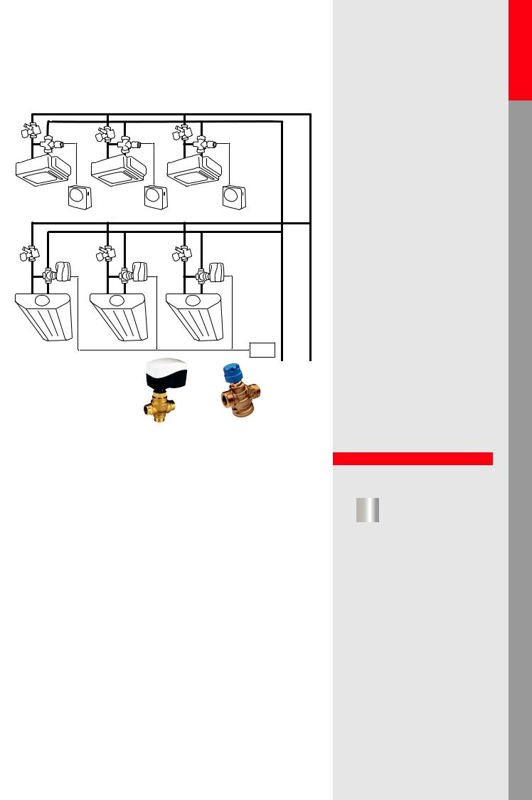
Heating |
Cooling |
Variable flow: Four-pipe Changeover (CO6) for radiant heating/cooling panels, chilled beams, etc. with PICV control valve
6-way value |
FAN COIL UNITS (FCU) |
|

 PICV
PICV
6-way value 
CHILLED PANELS
PICV
BMS |
Danfoss products:
6-way valve + PICV: NovoCon ChangeOver6 +AB-QM
Explanation
Return of investment
•Only two valves are needed instead of four. One for changeover* and one for heating/ cooling control
•Very energy efficient thanks to high ∆T and no overflows*
•Low commissioning* cost because only the flow needs to be set either on PICV or on BMS when using a digital actuator
•BMS costs are reduced because only one datapoint is needed
Design
•Easy selection of PICV, only the flow is required for sizing
•No Kv or authority* calculations needed
•The Δp on CO6 valve does need to be checked
•Perfect balance and control under all loads ensuring precise room temperature control
Operation/Maintenance
•Simplified construction because of reduction of components and pre-built sets
•One valve controls both cooling and heating
•Low complaint costs because of perfect balance and perfect control at all loads
•No cross flow between heating and cooling
•Low operational and upkeep cost. Flushing, purging, energy allocation and management can all be done through BMS.
Control
•Perfect control because of full authority*
•Individual settings for cooling and heating (flow), so perfect control in both situations
•Precise room temperature control
•Digital actuator ensures further saving with energy measurement and management function
16 |
*see page 54-55 |
Heating |
Cooling |
Variable flow: Two-pipe heating/cooling system with central changeover*
FAN COIL UNITS (FCU)
PICV-1
RC 

CHILLED PANELS
PICV-2
RC |
<![if ! IE]> <![endif]>COOLING |
<![if ! IE]> <![endif]>RETURN |
| <![if ! IE]> <![endif]>SUPPLY/RETURN |
||
| <![if ! IE]> <![endif]>HEATING |
<![if ! IE]> <![endif]>SUPPLY |
|
Danfoss products:
PICV-1: AB-QM 4.0 + TWA-Q |
PICV-2: AB-QM 4.0 + AMI-140 |
Explanation
Return of investment
•Heavily reduced construction cost due to elimination of a secend set of pipes
•Extra costs if automatic changeover* is required
•Proportional pump control is recommended
Design
•Simple PICV selection according to cooling flow, which is usually the highest
•The change-over valve needs to be selected according to the biggest flow rate (cooling) and a big Kvs is recommend to reduce the pumping cost*
•Different flow rates for heating and cooling need to be ensured, either by limiting the actuator stroke or by the ability to remotely set the maximum flow, (digital actuator)
•In most cases a different pump head is needed for heating and cooling
Operation/Maintenance
•Simple system setup with few valves, so low maintenance cost
•The seasonal changeover* needs to be managed
•No overflow* (if flow can be set for different heating/cooling mode)
Control
• Simultaneous heating and cooling in different rooms is not possible
• Perfect hydronic balancing and control with PICV
• ON/OFF control results in overflows when the flow limitation is not solved for lower flow demand (heating)
Acceptable |
<![if ! IE]> <![endif]>applicationsHydronic Commercial |
|
1.1.1.10 |
||
1 |
2 |
<![if ! IE]> <![endif]>applicationsHydronic Residential |
|
|
2 |
3 |
3 |
<![if ! IE]> <![endif]>loopMixing |
1 |
|
|
|
|
|
1.Central Changeover Valve
2.Pressure Independent Control Valve (PICV)
3.Room thermostat (RC)
In this application a central change |
<![if ! IE]> <![endif]>applicationsAHU coolingAHU |
||||
|
|||||
guarantees that the rooms can be cooled |
|
||||
and heated. It is strongly recommended |
|
||||
to use a PICV to control the temperature |
|
||||
because of the different flow require- |
|
||||
ments for the heating and cooling. |
<![if ! IE]> <![endif]>applicationsAHU heatingAHU |
||||
|
|
|
|
|
|
Performance |
|
|
|
||
|
|
|
|
||
|
Return of investment |
|
|
|
|
|
|
|
|
|
<![if ! IE]> <![endif]>Chillers |
|
|
|
|
|
|
|
poor |
acceptable |
excellent |
||
|
<![if ! IE]> <![endif]>applications |
||||
|
Design |
|
|
|
|
|
|
|
|
|
|
|
|
|
|
|
|
|
|
|
|
|
|
|
poor |
acceptable |
excellent |
|
|
|
Operation/Maintenance |
|
|
<![if ! IE]> <![endif]>Boilers |
|
|
|
|
|
|
|
|
|
|
|
|
|
|
|
|
|
|
<![if ! IE]> <![endif]>applications |
|
Control |
acceptable |
excellent |
||
|
poor |
|
|||
|
|
|
|
|
|
|
|
|
|
|
|
|
poor |
acceptable |
excellent |
|
|
|
|
|
|
|
<![if ! IE]> <![endif]>water Hot |
*see page 54-55 |
17 |

| <![if ! IE]> <![endif]>Hydronic applications |
<![if ! IE]> <![endif]>Commercial |
|
|
| <![if ! IE]> <![endif]>Hydronic applications |
<![if ! IE]> <![endif]>Residential |
<![endif]>Mixing loop
<![if ! IE]><![endif]>AHU cooling
<![if ! IE]><![endif]>AHU applications
<![if ! IE]><![endif]>Boilers applications Chillers applications AHU heating
<![if ! IE]><![endif]>AHU applications
<![if ! IE]><![endif]>Hot water
 Not Recommended
1.1.2.1
2
4
3
1
1.3-way Control Valve (CV)
2.Manual Balancing Valve (MBV)
3.Partner Valve* (MBV)
4.Building Management System (BMS) or Room temperature Control (RC)
In this application temperature control on the terminal unit is done by using 3-way valves. Manual balancing valves are used to create hydronic balance in the system. This application should be avoided due to its high energy inefficiency.
Performance
Return of investment
|
|
|
poor |
acceptable |
excellent |
Design
|
|
|
poor |
acceptable |
excellent |
Operation/Maintenance
|
|
|
poor |
acceptable |
excellent |
Control |
|
|
|
|
|
|
|
|
poor |
acceptable |
excellent |
ON/OFF |
|
Modulation |
control |
|
control |
Heating |
Cooling |
Constant flow: 3-way valve with manual balancing (in fan-coil, chilled beam etc. application)
FAN COIL UNITS (FCU)
MBV-1 |
|
|
CV-1 |
|
|
RC |
|
<![if ! IE]> <![endif]>MBV-1 |
|
|
|
|
CHILLED PANELS |
|
MBV-1 |
|
|
CV-2 |
|
<![if ! IE]> <![endif]>2 |
|
|
<![if ! IE]> <![endif]>MBV- |
|
|
BMS |
Danfoss products: |
|
|
CV-1: VZL3 + TWA-ZL CV-2: VZ3 +AME130 |
MBV-1: MSV-BD |
MBV-2: MSV-F2 |
Explanation |
|
|
Return of investment
•Many components are needed: a 3-way valve and a balancing valve per terminal unit and additional branch valves for commissioning*
•Extremely high operational cost, very energy inefficient
•The flow is close to constant, no variable speed drive applied
•In partial loads very low ΔT in the system, so boilers and chillers run at very low efficiency
Design
•Kv calculation is required, as well as an authority calculation* for the 3-way valve in case of modulation
•A by-pass needs to be sized or a balancing valve should be fitted. Otherwise big overflows in partial loads can occur causing terminal unit starvation and energy inefficiencies.
•For the Pump head calculation partial load needs to be considered if overflows on the by-pass are expected
Operation/Maintenance
•Commissioning of the system is required
•The hydronic balance at fulland partial load is acceptable
•Huge pump energy consumption due to constant operation
•High energy consumption (low ΔT)
Control
•The water distribution and the available pressure on the terminal units are more or less constant under all loads
•The room temperature control is satisfactory
•An oversized control valve will result in low rangeability and oscillation* with modulation
18 |
*see page 54-55 |
Heating |
Cooling |
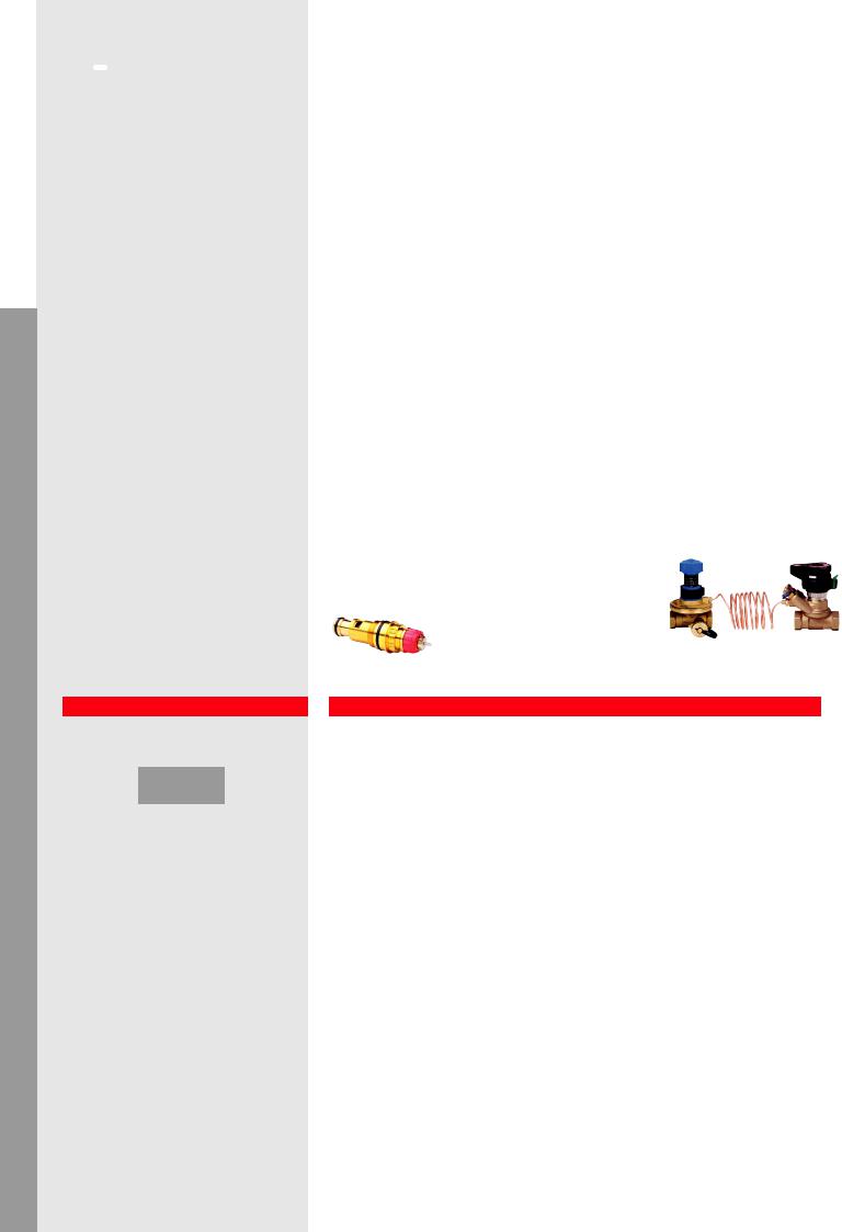
Constant flow: 3-way valve with flow limiter on terminal units (fan-coil, chilled beam etc. application)
FL |
CV-1 |
|
|
|
|
|
|
|
RC |
|
|
|
|
|
CHILLED PANELS |
FL |
CV-2 |
|
|
|
|
|
|
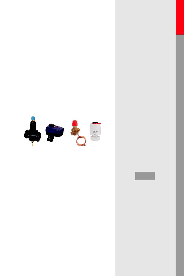
Danfoss products: |
|
BMS |
|
|
|
||
|
CV-1: VZL3 + TWA-ZL |
CV-2: VZ3 +AMV-130 |
FL: AB-QM |
Explanation |
|
|
|
Return of investment
•Many components are needed: a 3-way valve and an automatic flow limiter per terminal unit
•Fairly simple valve setup, no need for a balancing valve in by-pass or other valves for commissioning*
•Extremely high operational cost, very energy inefficient
•The flow close to constant, no variable speed drive applied
•In partial loads very low ΔT in the system, so boilers and chillers run at very low efficiency
Design
•Kv calculation is required, as well as an authority* calculation for the 3-way valve in case of modulation.
•Sizing and presetting of the flow limiters is based on the nominal flow of terminal unit
•For the Pump head calculation partial load needs to be considered if overflows on the by-pass are expected.
Operation/Maintenance
•Commissioning of the system is required
•The hydronic balance at fulland partial load is acceptable
•Huge pump energy consumption due to constant operation
•High energy consumption (low ΔT)
Control
•The water distribution and the available pressure on the terminal units are more or less constant under all loads
•The room temperature control is satisfactory
•An oversized control valve will result in low rangeability and oscillation* with modulation
Not Recommended 
1.1.2.2
2 
3
1
1.3-way Control Valve (CV)
2.Flow Limiter (FL)
3.Building Management System (BMS) or Room temperature Control (RC)
In this application temperature control on the terminal unit is done by using 3-way valves. Automatic flow limiters are used to create hydronic balance in the system. This application should be avoided due to its high energy inefficiency.
Performance
Return of investment
|
|
|
poor |
acceptable |
excellent |
Design
|
|
|
poor |
acceptable |
excellent |
Operation/Maintenance
|
|
|
poor |
acceptable |
excellent |
Control |
|
|
|
|
|
|
|
|
poor |
acceptable |
excellent |
ON/OFF |
|
Modulation |
control |
|
control |
<![endif]>applications Hydronic applications Hydronic
<![if ! IE]><![endif]>Residential Commercial
<![if ! IE]><![endif]>loop Mixing
<![if ! IE]><![endif]>applications AHU
<![if ! IE]><![endif]>cooling AHU
<![if ! IE]><![endif]>applications Boilers applications Chillers applicationsheating AHUAHU
<![if ! IE]><![endif]>water Hot
*see page 54-55 |
19 |
| <![if ! IE]> <![endif]>Hydronic applications |
<![if ! IE]> <![endif]>Commercial |
|
|
| <![if ! IE]> <![endif]>Hydronic applications |
<![if ! IE]> <![endif]>Residential |
|
|
<![endif]>Mixing loop
<![if ! IE]><![endif]>AHU cooling
<![if ! IE]><![endif]>AHU applications
<![if ! IE]><![endif]>Boilers applications Chillers applications AHU heating
<![if ! IE]><![endif]>AHU applications
<![if ! IE]><![endif]>Hot water
 Recommended
1.2.1.1
4 |
1 |
1 |
3 |
2 |
2 |
1.Termostatic Radiator Valve (TRV)
2.Return Locking Valve (RLV)
3.Δp controller (DPCV)
4.Partner valve*
In this application we ensure variable flow* on risers with thermostatic radiator valves. In case of presetting available
on TRV, ΔP controller used without flow limitation on the riser.
Performance
Return of investment
|
|
|
poor |
acceptable |
excellent |
Design
|
|
|
poor |
acceptable |
excellent |
Operation/Maintenance
|
|
|
poor |
acceptable |
excellent |
Control |
|
|
|
|
|
|
|
|
poor |
acceptable |
excellent |
Heating |
Cooling |
Two-pipe radiator heating system – risers with, thermostatic radiator valves
(with presetting)
TRV-2
TRV-1
DPCV |
DPCV |
Danfoss products:
TRV-1: RA build in + RA |
TRV-2: RA-N + RA |
DPCV: ASV-PV+ASV-BD |
Explanation
Return of investment
•Δp controller is more expensive compared to manual balancing
•Commissioning is not needed only Δp setting on Δp controller and flow pre-setting on TRVs
•Variable speed pump is recommended
Design
•Simple calculation method, Δp controlled risers can be calculated as independent loops (you can split the system by risers)
•The presetting calculation of radiators is needed,
•Kv calculation needed for Δp controller and control valve. Authority calculation also needed for proper TRV operation
•The Δp demand of loop should be calculated and set according nominal flow and system resistance
Operation/Maintenance
•Hydraulic regulation is in the bottom of risers and radiator presetting
•No hydronic interference among the risers
•Balancing at full and partial load – good – with TRV presetting
•Good efficiency: increased ΔT on riser and variable speed pump ensures energy saving
Control
•The efficiency of system good with individual presetting on radiators
•Low pumping costs – the flow rate of risers are limited.
•Maximum ΔT on risers
20 |
*see page 54-55 |
Heating |
Cooling |
Two pipe radiator heating system – risers with, thermostatic radiator valves (without presetting)
TRV
RLV-2
DPCV
Danfoss products:
DPCV: ASV-PV+ASV-BD
Explanation
Return of investment
•Δp controller plus flow limitation is more expensive then manual balancing
•Commissioning* is needed for flow limitation on the bottom of riser plus dp setting on Δp controller
•Variable speed pump is recommended
Design
•Simple calculation method, Δp controlled risers can be calculated as independent loops (you can split the system by risers)
•The presetting calculation of partner valve* for flow limitation is required
•Kv calculation needed for Δp controller and control valve. Authority *checking is also essential to know the control performance of TRV
•The Δp demand of loop should be calculated and set according nominal flow and system resistance
Operation/Maintenance
•Hydronic regulation is at the bottom of risers only
•No hydronic interference among the risers
•Balancing at full and partial load is acceptable
•Acceptable efficiency and variable speed pump ensures energy saving*
Control
•The flow limitation at the bottom of riser causes extra pressure drop within the Δp controlled loop therefore higher overflow appears during partial load (compared to presetting on TRV)
•Higher pumping costs* – however the flow rate of risers is limited slight oveflow occure within the riser during partial load condition
•Acceptable ΔT on risers (lower comparing to presetting on TRV)
|
|
|
|
|
1.2.1.2 |
|
|
|
|
|
|
|
<![if ! IE]> <![endif]>applicationsHydronic Commercial |
||||||||||||||
|
|
|
|
|
|
|
|
|
|
|
|
|
Acceptable |
|
|
|
|||||||||||
|
|
|
|
|
|
|
|
|
|
|
|
|
|
|
|
|
|
|
|
|
|
|
|
|
|
|
|
|
|
|
|
|
|
|
|
|
|
|
|
|
|
|
|
|
|
|
|
|
|
|
|
|
|
|
<![if ! IE]> <![endif]>applicationsHydronic Residential |
|
|
|
|
|
|
|
|
|
|
|
|
|
|
|
|
|
|
|
|
|
|
|
|
|
|
|
|
|
|
|
|
|
|
|
|
|
|
|
|
4 |
1 |
|
|
|
|
1 |
|
|
|
|
|
|
|
|
|
|
|
|
|
|
|
|
|
|
|
|
|
|
|
|
|
|
|
|
|
|
|
|
|
||||
|
|
|
|
|
3 |
|
|
|
|
|
|
|
|
|
|
|
|
|
|||||||||
|
|
|
|
|
|
|
|
|
|
|
|
|
|
|
|||||||||||||
|
|
|
|
|
|
|
|
|
|
|
|
|
|
|
|
|
|
|
|
||||||||
|
|
|
|
|
|
|
|
|
|
|
|
|
|
|
|
|
|
|
|
||||||||
|
|
|
|
|
|
|
|
|
|
|
|
|
|
|
|
|
|
|
|
||||||||
|
|
|
|
|
|
2 |
|
|
|
|
2 |
|
|
|
|
|
|
|
<![if ! IE]> <![endif]>Mixing |
||||||||
|
|
|
|
|
|
|
|
|
|
|
|
|
|
|
|
|
|||||||||||
|
|
|
|
|
|
|
|
|
|
|
|
|
|
|
|
|
|
|
|
|
|
|
|
|
|||
|
|
|
|
|
|
|
|
|
|
|
|
|
|
|
|
|
|
|
|
|
|
||||||
|
|
|
|
|
|
|
|
|
|
|
|
|
|
|
|
|
|
|
|
|
|
|
|
|
|
|
|
|
|
|
|
|
|
|
|
|
|
|
|
|
|
|
|
|
|
|
|
|
|
|
|
|
|
|
|
|
|
|
|
|
|
|
|
|
|
|
|
|
|
|
|
|
|
|
|
|
|
|
|
|
|
|
|
1. |
|
|
|
Termostatic Radiator Valve (TRV) |
|
|
<![if ! IE]> <![endif]>loop |
||||||||||||||||||||
2. |
|
|
|
Return Locking Valve (RLV) |
|
|
|||||||||||||||||||||
|
|
|
|
|
|
||||||||||||||||||||||
3. |
|
|
|
Δp controller (DPCV) |
|
|
|
|
|
|
|
|
|
||||||||||||||
4. |
|
|
|
Partner valve* |
|
|
|
|
|
|
|
|
|
||||||||||||||
In this application we ensure variable* |
|
|
<![if ! IE]> <![endif]>applications AHU cooling AHU |
||||||||||||||||||||||||
flow on risers with thermostatic radiator |
|
|
|
||||||||||||||||||||||||
valves. No possibility of presetting on TRV, |
|
|
|
||||||||||||||||||||||||
ΔP controller used with flow limitation on |
|
|
|
||||||||||||||||||||||||
the riser with partner valve*. |
|
|
|
|
|
|
|
|
<![if ! IE]> <![endif]>applicationsAHU heatingAHU |
||||||||||||||||||
|
|
|
|
|
|
|
|
|
|
|
|
|
|
|
|
|
|
|
|
|
|
|
|
|
|
|
|
Performance |
|
|
|
|
|
|
|
|
|
|
|
||||||||||||||||
|
|
|
|
|
|
|
|
|
|
|
|
|
|
||||||||||||||
|
|
|
|
|
Return of investment |
|
|
|
|
|
|
|
|
|
|||||||||||||
|
|
|
|
|
|
|
|
|
|
|
|
|
|
|
|
|
|
|
|
|
|
|
|
|
|
|
<![if ! IE]> <![endif]>Chillers |
|
|
|
|
|
|
|
|
|
|
|
|
|
|
|
|
|
|
|
|
|
|
|
|
|
|
|
|
|
|
|
|
|
poor |
|
acceptable |
|
excellent |
||||||||||||||||||
|
|
|
|
|
|
|
|
|
<![if ! IE]> <![endif]>applications |
||||||||||||||||||
|
|
|
|
|
Design |
|
|
|
|
|
|
|
|
|
|
|
|
|
|||||||||
|
|
|
|
|
|
|
|
|
|
|
|
|
|
|
|
|
|
|
|||||||||
|
|
|
|
|
|
|
|
|
|
|
|
|
|
|
|
|
|
|
|
|
|
|
|
|
|
|
|
|
|
|
|
|
|
|
|
|
|
|
|
|
|
|
|
|
|
|
|
|
|
|
|
|
|
|
|
|
|
|
|
|
poor |
|
acceptable |
|
excellent |
|
|
|
|||||||||||||||
|
|
|
|
|
Operation/Maintenance |
|
|
<![if ! IE]> <![endif]>Boilers |
|||||||||||||||||||
|
|
|
|
|
|
|
|
|
|
|
|
|
|
|
|
|
|
|
|
|
|
|
|
|
|
|
|
|
|
|
|
|
|
|
|
|
|
|
|
|
|
|
|
|
|
|
|
|
|
|
|
|
|||
|
|
|
|
|
|
|
|
|
|
|
|
|
|
|
|
|
|
|
|
|
|
|
|
|
|
|
<![if ! IE]> <![endif]>applications |
|
|
|
|
|
Control |
|
acceptable |
|
excellent |
||||||||||||||||||
|
|
|
|
|
poor |
|
|
|
|
|
|||||||||||||||||
|
|
|
|
|
|
|
|
|
|
|
|
|
|
|
|
|
|
|
|
|
|
|
|
|
|
|
|
|
|
|
|
|
|
|
|
|
|
|
|
|
|
|
|
|
|
|
|
|
|
|
|
|
|
|
|
|
|
|
|
|
poor |
|
acceptable |
|
excellent |
|
|
|
|||||||||||||||
|
|
|
|
|
|
|
|
|
|
|
|
|
|
|
|
|
|
|
|
|
|
|
|
|
|
|
<![if ! IE]> <![endif]>water Hot |
*see page 54-55 |
21 |
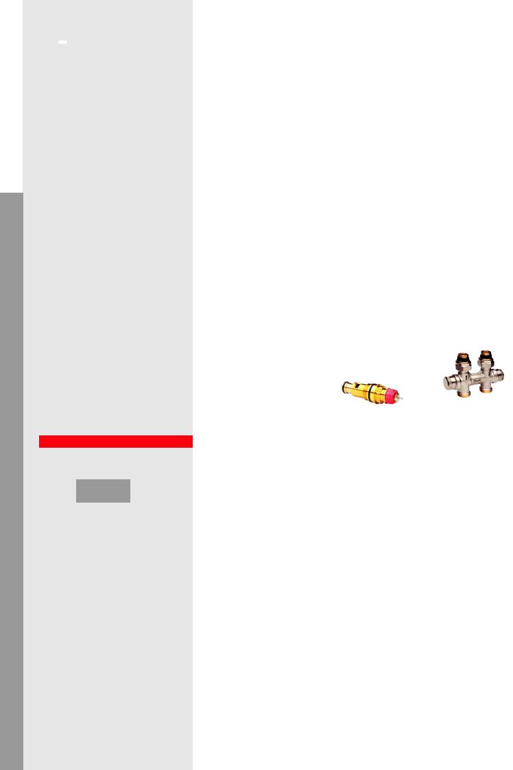
| <![if ! IE]> <![endif]>Hydronic applications |
<![if ! IE]> <![endif]>Commercial |
|
|
| <![if ! IE]> <![endif]>Hydronic applications |
<![if ! IE]> <![endif]>Residential |
|
|
<![endif]>Mixing loop
<![if ! IE]><![endif]>AHU cooling
<![if ! IE]><![endif]>AHU applications
<![if ! IE]><![endif]>Boilers applications Chillers applications AHU heating
<![if ! IE]><![endif]>AHU applications
<![if ! IE]><![endif]>Hot water
 Recommended
1.2.1.3
1
 2
2
3 |
4 |
1.Radiator Dynamic Valve (RDV)
2.Termostatic Radiator Valve (TRV)
3.Return Locking Valve (RLV)
4.Return Locking Dynamic Valve (RLDV)
In this application Pressure Independent Control Valves used in smaller radiator heating system combined with thermostatic senor (self-acting proportional room temperature control), give us a guarantee that regardless of the pressure oscillation inside the system, we will secure the right flow, allowing the right amount of heat to be delivered to the room. (Traditional radiator or„H” piece connection available).
Performance
Return of investment
|
|
|
poor |
acceptable |
excellent |
Design
|
|
|
poor |
acceptable |
excellent |
Operation/Maintenance
|
|
|
poor |
acceptable |
excellent |
Control |
|
|
|
|
|
|
|
|
poor |
acceptable |
excellent |
Heating |
Cooling |
Pressure Independent Control for radiator heating system

 TRV
TRV
RDV
 RLDV
RLDV
Danfoss products:
RDV: RA-DV + RA |
TRV-1: RA build in + RA |
RLDV: RLV-KDV |
Explanation
Return of investment
•A minimal number of components is needed which means less installation costs
•Low complaint costs because of perfect balance and perfect control at all loads
•Highly energy efficiency because of precise flow limitation at all loads
•High efficiency of boilers and pumping because of high ∆T in the system
Design
•Easy selection of valves based only on flow requirement
•No Kv or authority* calculation is needed, presetting calculation is based on flow demand
•Perfect balance and control at all loads
•Proportional pump control is recommended, pump speed can be optimized easily
•This solution applicable up to max. 135 l/h flow rate on terminal unit and max 60 kPa pressure difference across the valve
•Min available Δp on the valve 10 kPa
Operation/Maintenance
•Simplified construction because of reduction of components
•Set and forget, no complicated balancing procedures are needed
•Changes of flow setting do not influence the other users
•Flow verification is possible on the valve with special tool
Control
•Perfect control because of full authority*
•No overflows*
•Fix 2K proportional Xp band
•Fully pressure independent so no interference from pressure fluctuations and therefore stable room temperatures*
22 |
*see page 54-55 |
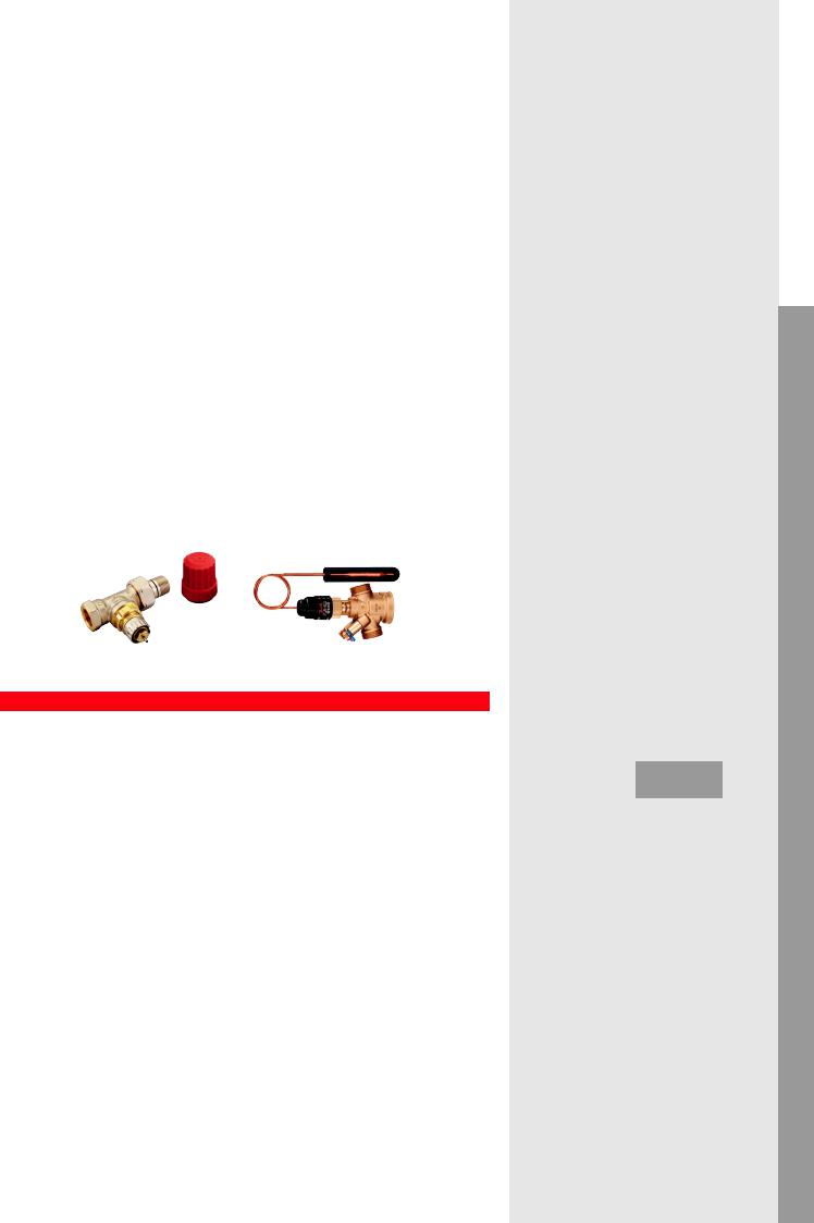
Heating |
Cooling |
Subordinated risers (staircase, bathroom, etc.) in twoor one-pipe radiator heating system without thermostatic valve
TRV
RLV 
PICV  +QT
+QT 
Danfoss products:
TRV: RA-N+RA |
PICV+QT: AB-QT |
Explanation
Return of investment
•QT (temperature limiter sensor) is an extra cost (flow limiter is recommended in any case)
•Commissioning of the system is not required only setting of flow on PICV and temperature on QT
•VSD pump is recommended
Design
•Simple calculation is required for riser flow, based on heat demand and ΔT, the size of radiator, convector has to be designed accordingly
•The flow is controlled by return temperature signal
•The presetting calculation of radiator is crucial due to no room temperature controller, the heat emission will depend on flow rate and size of radiator. The presetting calculation is based on flow rate among radiators and pressure drop of pipeline
•Simplified hydraulic calculation (you can split the system by risers)
Operation/Maintenance
•No overheating on riser during partial load condition (strongly recommended for renovation)
•Good balancing at full and partial load - additional energy saving*
•Higher efficiency, limited return temperature and variable speed pump ensures energy saving*
Control
•Inner rooms (typically bathrooms) have constant heat demand, to keep constant heat output, with increasing flow temperature, QT reduces the flow rate.
•Less overheating of risers – energy saving*
•ΔT increasement ensures lower heat loss and better heat production efficiency
•LOW pumping costs* – the flow rate of subordinated risers are limited and reduced even more with temperature limitation by QT
•Limited efficiency of QT control when flow temperature drops. Electronic controller (CCR3+) increases efficiency at higher outdoor temperature.
|
|
1.2.1.4 |
|
|
<![if ! IE]> <![endif]>applicationsHydronic Commercial |
||||||||||
|
|
Recommended |
|
|
|
||||||||||
|
|
|
|
|
|
|
|
|
|
|
|
|
|
<![if ! IE]> <![endif]>applications Hydronic Residential |
|
|
|
2 |
|
|
1 |
|
|
|
|
|
|
|
|||
|
|
|
|
|
|
|
|
|
|
|
|||||
|
|
|
|
|
|
|
|
|
|
|
|
||||
|
|
|
|
|
|
|
|
|
|
|
|
||||
|
|
|
|
|
|
|
|
|
|
|
|
||||
|
|
|
|
|
|
|
|
|
|
|
|
|
|||
|
|
3 |
|
|
|
|
|
|
|
<![if ! IE]> <![endif]>Mixing |
|||||
|
|
|
|
|
|
|
|
|
|
|
|
|
|||
|
|
|
|
|
|
|
|
|
|
|
|
|
|
||
|
|
|
|
|
|
|
|
|
|
|
|
|
|
||
1. |
Radiator Valve (without sensor) (RV) |
||||||||||||||
| <![if ! IE]> <![endif]>loop |
|||||||||||||||
2. |
Pressure Independent Control Valve |
||||||||||||||
|
|||||||||||||||
|
|
(PICV) |
|
|
|
|
|
|
|
|
|
||||
3. |
Temperature Sensor (QT) |
|
|
|
|||||||||||
In this application we have theoretical |
<![if ! IE]> <![endif]>applicationsAHU coolingAHU |
||||||||||||||
|
|||||||||||||||
constant flow* on subordinated risers and |
|
||||||||||||||
no thermostatic sensor on radiator valve |
|
||||||||||||||
(like staircase, bathroom etc.) For better |
|
||||||||||||||
efficiency we ensure variable flow* in case |
|
||||||||||||||
of partial load condition when the return |
|
||||||||||||||
temperature is increasing, with return |
|
||||||||||||||
flow temperature limitation. |
|
|
<![if ! IE]> <![endif]>applicationsAHU heatingAHU |
||||||||||||
|
|
|
|
|
|
|
|
|
|
|
|
|
|
||
Performance |
|
|
|
|
|
|
|
|
|||||||
|
|
|
|
|
|
|
|
|
|||||||
|
|
Return of investment |
|
|
|
||||||||||
|
|
|
|
|
|
|
|
|
|
|
|
|
|
<![if ! IE]> <![endif]>Chillers |
|
|
|
|
|
|
|
|
|
|
|
|
|
|
|
||
|
|
poor |
acceptable |
excellent |
|||||||||||
|
|
<![if ! IE]> <![endif]>applications |
|||||||||||||
|
|
Design |
|
|
|
|
|
|
|
|
|||||
|
|
|
|
|
|
|
|
|
|
|
|||||
|
|
|
|
|
|
|
|
|
|
|
|
|
|
||
|
|
|
|
|
|
|
|
|
|
|
|
|
|
|
|
|
|
poor |
acceptable |
excellent |
|
||||||||||
|
|
Operation/Maintenance |
|
|
<![if ! IE]> <![endif]>Boilers |
||||||||||
|
|
|
|
|
|
|
|
|
|
|
|
|
|
||
|
|
|
|
|
|
|
|
|
|
|
|
|
|
||
|
|
|
|
|
|
|
|
|
|
|
|
|
|
<![if ! IE]> <![endif]>applications |
|
|
|
Control |
acceptable |
excellent |
|||||||||||
|
|
poor |
|
||||||||||||
|
|
|
|
|
|
|
|
|
|
|
|
|
|
||
|
|
|
|
|
|
|
|
|
|
|
|
|
|
|
|
|
|
poor |
acceptable |
excellent |
|
||||||||||
|
|
|
|
|
|
|
|
|
|
|
|
|
|
<![if ! IE]> <![endif]>water Hot |
|
*see page 54-55 |
23 |

| <![if ! IE]> <![endif]>Hydronic applications Commercial |
|
|
|
|
|
|
Recommended |
|||||||||||||||||
|
|
|
|
1.2.1.5 |
|
|
||||||||||||||||||
|
|
|
|
|
|
|
|
|
|
|
|
|
|
|
|
|
|
|
|
|
|
|
|
|
| <![if ! IE]> <![endif]>Hydronic applications Residential |
|
|
|
|
|
|
|
|
|
|
|
|
|
|
|
|
|
|
|
|
|
|
|
|
|
|
|
|
|
|
|
|
|
|
|
|
|
|
|
|
|
|
|
|
|
|
|
||
|
|
|
|
|
|
|
|
|
|
|
|
|
|
|
|
|
|
|
|
|
|
|
|
|
|
|
|
|
|
|
|
|
2 |
|
|
|
|
|
|
|
|
|
|
|
|
|
|||
|
|
|
|
|
|
|
|
|
|
|
|
|
|
|
|
|
|
|
|
|||||
|
|
|
|
|
|
|
|
|
|
|
|
|
|
|
|
|
|
|
|
|
|
|
|
|
|
|
|
|
|
|
|
|
|
|
|
|
|
|
|
|
|
|
|
|
3 |
|
|
||
|
|
|
|
|
|
|
|
|
|
|
|
|
|
|
|
|
|
|
|
|
|
|
|
|
|
|
|
|
|
|
|
|
|
|
|
|
|
|
|
|
|
|
|
|
|
|
|
|
|
|
|
|
|
1 |
|
|
|
|
|
|
|
|
|
|
|
|
|
|||||||
|
|
|
|
|
|
|
|
|
|
|
|
|
|
|
|
|
|
|||||||
|
|
|
|
|
|
|
|
|
|
|
|
|
|
|
|
|
|
|||||||
|
1. |
Δp controller (DPCV) |
|
|
|
|
||||||||||||||||||
| <![if ! IE]> <![endif]>loop |
|
|
|
|
||||||||||||||||||||
2. |
Partner valve* |
|
|
|
|
|||||||||||||||||||
| <![if ! IE]> <![endif]>Mixing |
3. |
Manifold with presettable valves |
||||||||||||||||||||||
|
|
|
|
|
|
|
|
|
|
|
|
|
|
|
|
|
|
|
|
|
|
|
|
|
| <![if ! IE]> <![endif]>AHUapplications AHUcooling |
In this application we ensure variable |
|||||||||||||||||||||||
|
||||||||||||||||||||||||
|
flow* in the distribution pipeline and |
|||||||||||||||||||||||
|
constant differential pressure on each |
|||||||||||||||||||||||
|
manifold independently from temporal |
|||||||||||||||||||||||
|
load and pressure fluctuation in the |
|||||||||||||||||||||||
| <![if ! IE]> <![endif]>applicationsAHU heatingAHU |
system. Applicable for both radiator and |
|||||||||||||||||||||||
floor heating systems. |
|
|
|
|
||||||||||||||||||||
|
|
|
|
|
||||||||||||||||||||
|
|
|
Performance |
|
|
|
|
|||||||||||||||||
|
|
|
Return of investment |
|
|
|
|
|||||||||||||||||
| <![if ! IE]> <![endif]>applicationsChillers |
|
|
|
|
|
|
|
|
|
|
|
|
|
|
|
|
|
|
|
|
|
|
|
|
|
|
|
|
|
|
|
|
|
|
|
|
|
|
|
|
|
|
|
|
|
|
|
|
|
|
|
poor |
|
|
|
|
|
|
|
acceptable |
|
excellent |
||||||||||||
|
|
|
|
|
|
|
|
|
|
|
||||||||||||||
|
|
|
Design |
|
|
|
|
|
|
|
|
|
|
|
|
|
|
|
|
|
|
|
|
|
|
|
|
|
|
|
|
|
|
|
|
|
|
|
|
|
|
|
|
|
|
|
|
|
|
|
|
|
|
|
|
|
|
|
|
|
|
|
|
|
|
|
|
|
|
|
|
|
|
|
|
|
|
poor |
|
|
|
|
|
|
|
acceptable |
|
excellent |
|||||||||||
| <![if ! IE]> <![endif]>applications |
|
|
Operation/Maintenance |
|
|
|
|
|||||||||||||||||
|
|
|
|
|
|
|
|
|
|
|
|
|
|
|
|
|
|
|
|
|
|
|
|
|
|
|
|
|
|
|
|
|
|
|
|
|
|
|
|
|
|
|
|
|
|
|
|
|
|
|
|
poor |
|
|
|
|
|
|
|
acceptable |
|
excellent |
||||||||||||
| <![if ! IE]> <![endif]>Boilers |
|
|
|
|
|
|
|
|
|
|
||||||||||||||
|
|
Control |
|
|
|
|
||||||||||||||||||
|
|
|
|
|
|
|
|
|
|
|
|
|
|
|
|
|
|
|
|
|
|
|
|
|
|
|
|
|
|
|
|
|
|
|
|
|
|
|
|
|
|
|
|
|
|
|
|
|
|
|
|
|
poor |
|
|
|
|
|
|
|
acceptable |
|
excellent |
|||||||||||
| <![if ! IE]> <![endif]>Hot water |
|
|
|
|
|
|
|
|
|
|
|
|
|
|
|
|
|
|
|
|
|
|
|
|
Heating |
Cooling |
p control for manifold with individual zone/loop control
RC 
DPCV
Danfoss products:
Manifold: FHF + TWA-A |
DPCV: ASV-PV + ASV-BD |
Explanation
Return of investment
•Beside manifold we need DPCV with partner valve*. Heat meter is often used for individual flat connections
•Thermal actuator for zone control (floor heating) or thermostatic sensor (radiator)
•Commissioning is not needed, Δp setting and flow setting on manifold loops only
•With additional investment, the users’ comfort can be increased with individual, time based wired or wireless room temperature control
•Variable speed pump is recommended
Design
•Simple DPCV sizing according kvs calculation and total flow demand of manifold
•Presetting calculation is needed for built in zone valves only
•The presetting of loops, limiting the flow to be ensured no under/overflow on connections
Operation/Maintenance
•Reliable, pressure independent solution for individual flat/manifold connection
•Partner valve* can have different functions like, impulse tube connection, shut off, etc.
•Flow setting can be done accurately via Δp setting on DPCV with heat meter most often used
•NO noise risk thanks for Δp controlled manifolds
•High efficiency, especially with individual programmable room control
Control
•Stable pressure difference for manifolds
•Flow limitation is solved, no overflow* or underflow per connections
•Thermal actuators (floor heating) ensure manifold or individual time based room temperature zone control (ON/OFF) with suitable room controller
•Thermostatic sensor (radiator) ensures proportional room control with proper Xp band
24 |
*see page 54-55 |
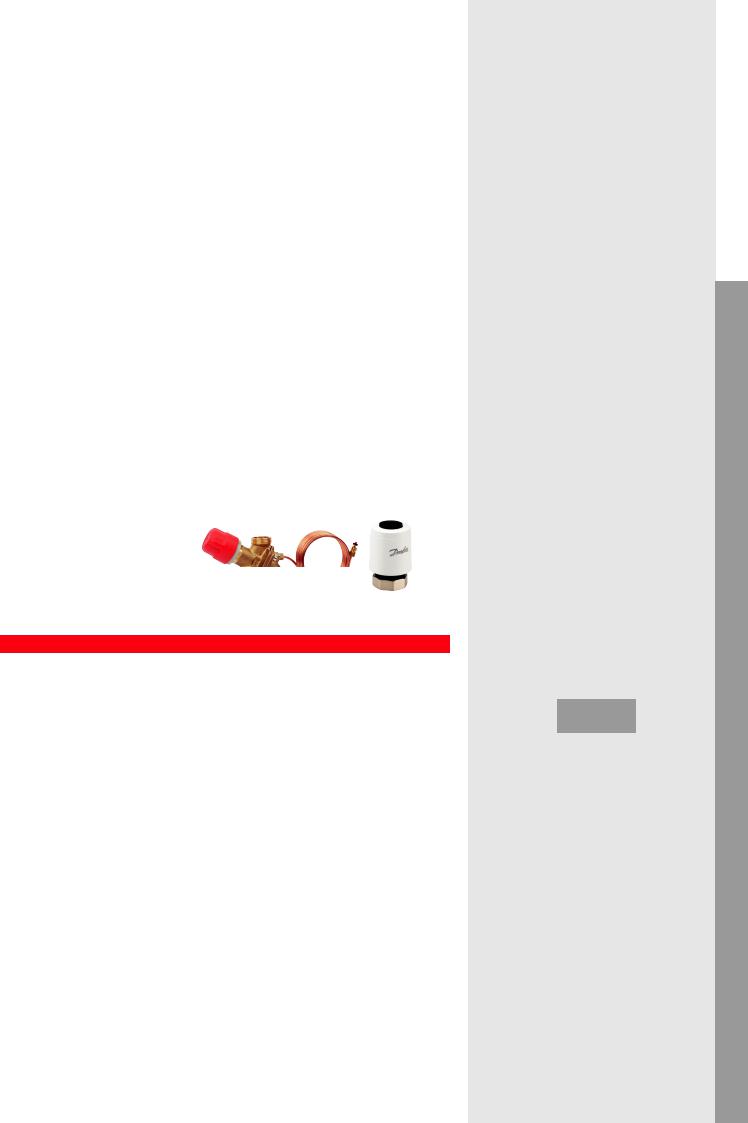
Heating |
Cooling |
p control and flow limitation for manifold with central zone control
DPCV
RC 

Danfoss products:
Manifold: FHF |
ABV: AB-PM +TWA-Q (optional) |
Explanation
Return of investment
•DPCV and impulse tube connection needed only. Heat meter often used for individual flat connection
•Thermal actuator for zone control as option (installed on DPCV)
•Individual zone control (floor heating) or thermostatic sensor (radiator) also possible
•Installation time can be reduced with usage of set solution
•Commissioning is not needed, flow setting on DPCV only and presetting of each loop
•Variable speed pump is recommended
Design
•Simple, no kvs and authority* calculation, valve selection based on flow rate and Δp demand of loop
•Presetting calculation is needed for built-in zone valves (if there are)
•The presetting of flow limitation ensures no under/overflow on manifold
•Pump head calculation is very simple, min available pressure difference for DPCV (included the loop Δp) is given
Operation/Maintenance
•Reliable, pressure independent solution for individual flat connection
•Partner valve* – if applied - can have different functions like, impulse tube connection, shut off, etc.
•No noise risk thanks to Δp controlled manifold
•High efficiency, especially with individual programmable room control
Control
•Maximized pressure difference for manifold
•Flow limitation is solved, no overflow* or underflow per connections
•...but slight overflow within the loop during partial load
•Thermal actuator ensures zone control (ON/OFF) with suitable room controller
1.2.1.6 |
|
<![if ! IE]> <![endif]>applicationsHydronic Commercial |
Recommended |
|
|
1 |
|
<![if ! IE]> <![endif]>applicationsHydronic Residential |
|
|
|
|
2 |
|
1. |
Δp controller (DPCV) |
2. |
<![if ! IE]> <![endif]>loopMixing |
Manifold with presettable valves |
In this application we ensure variable |
<![if ! IE]> <![endif]>applicationsAHU coolingAHU |
|||||
flow* in the distribution pipeline and |
||||||
|
||||||
maximum pressure difference on each |
|
|||||
manifold independently from temporal |
|
|||||
load and pressure fluctuation in the |
|
|||||
system. Furthermore, we limit the flow for |
|
|||||
manifold and able to ensure zone control |
|
|||||
with adding thermal actuator on DPCV. |
|
|||||
Applicable for both radiator and floor |
<![if ! IE]> <![endif]>applicationsAHU heatingAHU |
|||||
heating systems. |
|
|
|
|||
|
|
|
|
|
||
Performance |
|
|
|
|||
|
|
|
|
|||
|
Return of investment |
|
|
|
||
|
|
|
|
|
<![if ! IE]> <![endif]>Chillers |
|
|
|
|
|
|
||
|
poor |
acceptable |
excellent |
|||
|
<![if ! IE]> <![endif]>applications |
|||||
|
Design |
|
|
|
||
|
|
|
|
|
||
|
|
|
|
|
||
|
|
|
|
|
|
|
|
poor |
acceptable |
excellent |
|
||
|
Operation/Maintenance |
|
|
<![if ! IE]> <![endif]>Boilers |
||
|
|
|
|
|
||
|
|
|
|
|
||
|
|
|
|
|
<![if ! IE]> <![endif]>applications |
|
|
Control |
acceptable |
excellent |
|||
|
poor |
|
||||
|
|
|
|
|
||
|
|
|
|
|
|
|
|
poor |
acceptable |
excellent |
|
||
|
|
|
|
|
<![if ! IE]> <![endif]>water Hot |
|
*see page 54-55 |
25 |
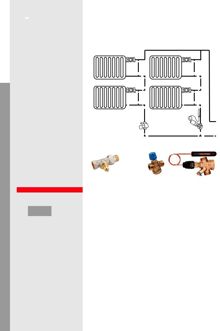
| <![if ! IE]> <![endif]>Hydronic applications |
<![if ! IE]> <![endif]>Commercial |
|
|
| <![if ! IE]> <![endif]>Hydronic applications |
<![if ! IE]> <![endif]>Residential |
|
|
<![endif]>Mixing loop
<![if ! IE]><![endif]>AHU cooling
<![if ! IE]><![endif]>AHU applications
<![if ! IE]><![endif]>Boilers applications Chillers applications AHU heating
<![if ! IE]><![endif]>AHU applications
<![if ! IE]><![endif]>Hot water
 Recommended
1.2.2.1
 1
1
 1
1
3
2 

1.Radiator Valve (TRV)
2.Pressure Independent Control Valve (PICV)
3.Optional - Temperature Sensor (QT)
This application is suitable for renovating of vertical one-pipe radiator heating system. We recommend high capacity thermostatic radiator valve and flow limiter installation on riser. For better efficiency we optionally recommend to use return temperature control with QT (Thermostatic Sensor)
Performance
Return of investment
|
|
|
poor |
acceptable |
excellent |
Design
|
|
|
poor |
acceptable |
excellent |
Operation/Maintenance
|
|
|
poor |
acceptable |
excellent |
Control |
|
|
|
|
|
|
|
|
poor |
acceptable |
excellent |
With QT |
|
Without QT |
Heating |
Cooling |
One-pipe radiator heating system renovation with automatic flow limitation and possible self-acting return temperature limitation
TRV
PICV |
PICV+QT |
|
Danfoss products:
TRV: RA-G + RA |
PICV: AB-QM |
PICV+QT: AB-QT |
Explanation
Return of investment
•Investment cost are higher (thermostatic radiator valve + flow limiter + QT on risers) compared to manual balancing
•Simple QT installation with low extra cost
•No commissioning* demand only flow setting
•Variable speed pump is recommended (without QT the pump control is not needed)
Design
•„α” (radiator share) calculation with iteration
•Big capacity TRV is needed to increase the„α”
•Radiator size depends on flow temperature changes
•Gravitation effect should be taken into account
•Simple hydronic calculation regarding riser controller, selection based on flow rate but we need to ensure the minimum available pressure on it
•QT setting depends on system conditions
Operation/Maintenance
•System less sensitive for gravitation effect due to flow limitation
•„α” (radiator share) sensitive for installation punctuality
•Real constant flow* without QT, variable flow* with QT
•QT contributes to energy saving* on pumping
•QT ensures more accurate heat cost allocation
Control
•Accurate and simple water distribution among risers
•Improved room temperature control
•The radiator heat emission depends on varying flow temperature
•Heat gain from pipe in the rooms affects the room temperature
•QT effect is limited in case of higher outdoor temperature
26 |
*see page 54-55 |
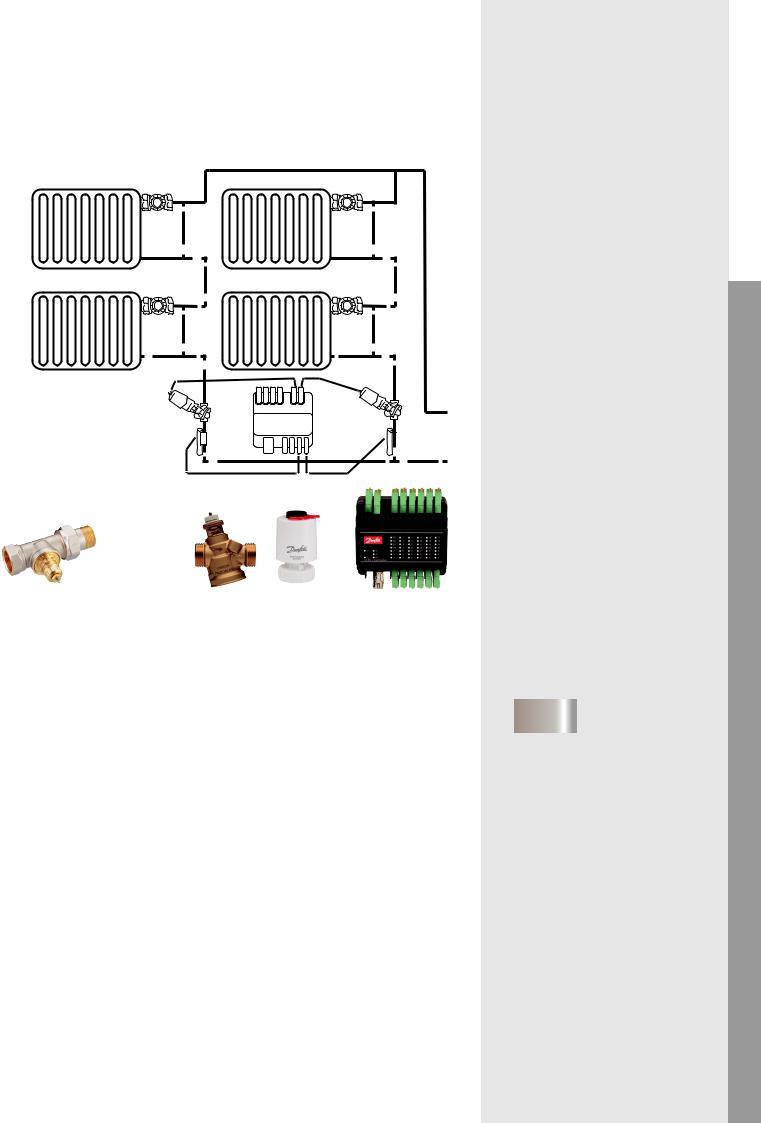
Heating |
Cooling |
One-pipe radiator heating system renovation with electronic flow limitation and return temperature control
TRV
PICV
CCR3+

 TS
TS
Danfoss products:
TRV: RA-G + RA |
PICV: AB-QM+TWA-Q |
CCR3+ |
Explanation
Return of investment
•High investment cost (thermostatic radiator valve + flow limiter with thermal actuator, sensor on risers + CCR3+)
•Electronic wiring is needed, programing CCR3+
•No commissioning* demand only flow setting
•Variable speed pump is recommended
Design
•„α” (radiator share) calculation with iteration
•Big capacity TRV is needed to increase the„α”
•Radiator size depends on flow temperature changes
•Gravitation effect should be taken into account
•Simple hydronic calculation regarding riser controller, selection based on flow rate but we need to ensure the minimum available pressure on it
•Defining of needed return characteristic
Operation/Maintenance
•The system less sensitive for gravitation effect due to flow limitation
•„α” (radiator share) sensitive for installation punctuality
•Programming CCR3+, data logging, remote maintenance and access
•Higher efficiency due to improved ΔT, and reduced pipe heat loss
Control
•Accurate and simple water distribution among risers
•Improved room temperature control
•The radiator heat emission depends on varying flow temperature
•Heat gain from pipe in the rooms affects the room temperature
•CCR3+ Weather compensation on return temperature on all individual risers
|
|
|
1.2.2.2 |
|
|
|
|
|
<![if ! IE]> <![endif]>applicationsHydronic Commercial |
||||||||
|
|
|
Recommended |
|
|
|
|
|
|
||||||||
|
|
|
|
|
|
|
|
|
|
|
|
|
|
|
|
|
|
|
|
|
|
|
|
|
|
|
|
|
|
|
|
|
|
|
<![if ! IE]> <![endif]>applicationsHydronic Residential |
|
|
|
|
1 |
|
|
|
|
|
|
|
|
|
||||
|
|
|
|
|
|
|
|
|
|
|
|
|
|
|
|
|
|
|
|
|
|
|
|
|
|
|
|
|
|
|
|
|
|
|
|
|
|
|
|
1 |
|
|
|
|
|
|
|
|
|
||||
|
|
|
|
|
|
|
|
|
|
|
|
|
|
||||
|
|
|
|
|
|
|
|
|
|
|
|
|
|
|
|
|
|
|
|
|
|
4 |
|
3 |
|
|
|
|
|
||||||
|
|
|
|
|
|
|
|
|
|||||||||
|
|
|
|
|
|
|
|
|
|
|
|
|
|
|
|
|
|
|
|
|
|
2 |
|
|
|
|
|
CCR3+ |
|
|
|
|
|||
|
|
|
|
|
|
|
|
|
|
|
|
|
|
<![if ! IE]> <![endif]>loop Mixing |
|||
|
|
|
|
|
|
|
|
|
|
|
|
|
|
||||
|
|
|
|
|
|
|
|
|
|
|
|
|
|
|
|
|
|
|
|
|
|
|
|
|
|
|
|
|
|
|
|
|
|
|
|
1. |
|
Radiator Valve (TRV) |
|
|
|
|
|
||||||||||
|
|
|
|
|
|
|
|||||||||||
2. |
|
Pressure Independent Control Valve |
|
|
|
||||||||||||
|
|
|
(PICV) |
|
|
|
|
|
|
|
|
|
|
|
|
|
|
3. |
|
Elecrtonic Controller (CCR3+) |
|
|
|
||||||||||||
4. |
|
Temperature sensor (TS) |
|
|
|
|
|
<![if ! IE]> <![endif]>applicationsAHU coolingAHU |
|||||||||
|
This application is suitable for renovating |
|
|
||||||||||||||
|
|
|
|
||||||||||||||
|
of vertical one-pipe radiator heating |
|
|
|
|||||||||||||
|
system. We recommend high capacity |
|
|
|
|||||||||||||
|
thermostatic radiator valve and flow limi- |
|
|
|
|||||||||||||
|
ter installation on riser. For best efficiency |
|
|
|
|||||||||||||
|
we recommend to use CCR3+ (Electronic |
|
|
<![if ! IE]> <![endif]>applicationsAHU heatingAHU |
|||||||||||||
|
Controller) |
|
|
|
|
|
|
|
|
|
|
|
|
|
|||
|
|
|
|
|
|
|
|
|
|
|
|
|
|
|
|
|
|
Performance |
|
|
|
|
|
|
|
|
|
|
|
||||||
|
|
|
|
|
|
|
|
|
|
|
|
|
|
||||
|
|
|
Return of investment |
|
|
|
|
|
|
||||||||
|
|
|
|
|
|
|
|
|
|
|
|
|
|
|
|
|
<![if ! IE]> <![endif]>Chillers |
|
|
|
|
|
|
|
|
|
|
|
|
|
|
|
|
|
|
|
|
|
poor |
acceptable |
excellent |
||||||||||||
|
|
|
|
|
<![if ! IE]> <![endif]>applications |
||||||||||||
|
|
|
Design |
|
|
|
|
|
|
|
|
|
|
|
|
|
|
|
|
|
|
|
|
|
|
|
|
|
|
|
|
|
|
|
|
|
|
|
|
|
|
|
|
|
|
|
|
|
|
|
|
|
|
|
|
|
|
|
|
|
|
|
|
|
|
|
|
|
|
|
|
|
|
|
poor |
acceptable |
excellent |
|
|
|
|||||||||
|
|
|
Operation/Maintenance |
|
|
|
|
|
<![if ! IE]> <![endif]>Boilers |
||||||||
|
|
|
|
|
|
|
|
|
|
|
|
|
|
|
|
|
|
|
|
|
|
|
|
|
|
|
|
|
|
|
|
|
|||
|
|
|
|
|
|
|
|
|
|
|
|
|
|
|
|
|
<![if ! IE]> <![endif]>applications |
|
|
|
Control |
acceptable |
excellent |
||||||||||||
|
|
|
poor |
|
|
|
|||||||||||
|
|
|
|
|
|
|
|
|
|
|
|
|
|
|
|
|
|
|
|
|
|
|
|
|
|
|
|
|
|
|
|
|
|
|
|
|
|
|
poor |
acceptable |
excellent |
|
|
|
|||||||||
|
|
|
|
|
|
|
|
|
|
|
|
|
|
|
|
|
<![if ! IE]> <![endif]>water Hot |
*see page 54-55 |
27 |
 Loading...