


MAKING MODERN LIVING POSSIBLE
Programming Guide
VLT® AQUA Drive FC 202
vlt-drives.danfoss.com

Contents |
Programming Guide |
|
|
Contents
1 Introduction |
4 |
1.1 Purpose of the Manual |
4 |
1.2 Additional Resources |
4 |
1.3 Software Version |
4 |
1.4 Approvals |
4 |
1.5 Symbols |
4 |
1.6 De€nitions |
4 |
1.6.1 Frequency Converter |
4 |
1.6.2 Input |
4 |
1.6.3 Motor |
4 |
1.6.4 References |
5 |
1.6.5 Miscellaneous |
5 |
1.7 Abbreviations, Symbols, and Conventions |
7 |
1.8 Safety |
7 |
1.9 Electrical Wiring |
10 |
2 How to Program |
13 |
2.1 The Graphical and Numerical Local Control Panel |
13 |
2.2 How to Program on the Graphical LCP |
13 |
2.2.1 The LCP Display |
14 |
2.2.2 Quick Transfer of Parameter Settings between Multiple Frequency Converters |
17 |
2.2.3 Display Mode |
17 |
2.2.4 Display Mode - Selection of Readouts |
17 |
2.2.5 Parameter Set-up |
18 |
2.2.6 Quick Menu Key Functions |
18 |
2.2.7 Quick Menu, Q3 Function Set-ups |
19 |
2.2.8 Quick Menu, Q4 SmartStart |
22 |
2.2.9 Main Menu Mode |
22 |
2.2.10 Parameter Selection |
22 |
2.2.11 Changing Data |
23 |
2.2.12 Changing a Text Value |
23 |
2.2.13 Changing a Data Value |
23 |
2.2.14 In€nitely Variable Change of Numeric Data Value |
23 |
2.2.15 Value, Step-by-step |
23 |
2.2.16 Readout and Programming of Indexed Parameters |
24 |
2.2.17 How to Program on the Numerical Local Control Panel |
24 |
2.2.18 LCP Keys |
25 |
3 Parameter Description |
27 |
3.1 Parameter Selection |
27 |
MG20OA02 |
Danfoss A/S © 05/2016 All rights reserved. |
1 |

Contents |
VLT® AQUA Drive FC 202 |
3.2 Parameters 0-** Operation and Display |
28 |
3.2.1 0-0* Basic Settings |
28 |
3.3 Parameters 1-** Load and Motor |
41 |
3.4 Parameters 2-** Brakes |
60 |
3.5 Parameters 3-** Reference/Ramps |
63 |
3.6 Parameters 4-** Limits/Warnings |
69 |
3.7 Parameters 5-** Digital In/Out |
73 |
3.8 Parameters 6-** Analog In/Out |
88 |
3.9 Parameters 8-** Communications and Options |
97 |
3.10 Parameters 9-** PROFIBUS |
105 |
3.11 Parameters 10-** CAN Fieldbus |
105 |
3.12 Parameters 13-** Smart Logic |
108 |
3.13 Parameters 14-** Special Functions |
126 |
3.14 Parameters 15-** Drive Information |
134 |
3.15 Parameters 16-** Data Readouts |
140 |
3.16 Parameters 18-** Data Readouts 2 |
147 |
3.17 Parameters 20-** FC Closed Loop |
149 |
3.18 Parameters 21-** Extended Closed Loop |
159 |
3.19 Parameters 22-** Application Functions |
167 |
3.20 Parameters 23-** Time-based Functions |
181 |
3.21 Parameters 24-** Application Functions 2 |
191 |
3.22 Parameters 25-** Cascade Controller |
192 |
3.23 Parameters 26-** Analog I/O Option MCB 109 |
202 |
3.24 Parameters 29-** Water Application Functions |
208 |
3.25 Parameters 30-** Special Features |
216 |
3.26 Parameters 31-** Bypass Option |
216 |
3.27 Parameters 35-** Sensor Input Option |
218 |
4 Parameter Lists |
221 |
4.1 Parameter Options |
221 |
4.1.1 Default Settings |
221 |
4.1.2 0-** Operation / Display |
222 |
4.1.3 1-** Load and Motor |
224 |
4.1.4 2-** Brakes |
226 |
4.1.5 3-** Reference / Ramps |
227 |
4.1.6 4-** Limits / Warnings |
228 |
4.1.7 5-** Digital In/Out |
229 |
4.1.8 6-** Analog In/Out |
231 |
4.1.9 8-** Comm. and Options |
233 |
4.1.10 9-** PROFIdrive |
234 |
4.1.11 10-** CAN Fieldbus |
235 |
2 |
Danfoss A/S © 05/2016 All rights reserved. |
MG20OA02 |

Contents |
Programming Guide |
|
|
4.1.12 13-** Smart Logic |
236 |
4.1.13 14-** Special Functions |
237 |
4.1.14 15-** Drive Information |
238 |
4.1.15 16-** Data Readouts |
240 |
4.1.16 18-** Info & Readouts |
242 |
4.1.17 20-** Drive Closed Loop |
243 |
4.1.18 21-** Ext. Closed Loop |
244 |
4.1.19 22-** Appl. Functions |
246 |
4.1.20 23-** Time-based Functions |
248 |
4.1.21 24-** Appl. Functions 2 |
249 |
4.1.22 25-** Cascade Controller |
249 |
4.1.23 26-** Analog I/O Option |
250 |
4.1.24 29-** Water Application Functions |
252 |
4.1.25 30-** Special Features |
254 |
4.1.26 31-** Bypass Option |
254 |
4.1.27 35-** Sensor Input Option |
254 |
5 Troubleshooting |
256 |
5.1 Status Messages |
256 |
5.1.1 Warnings/Alarm Messages |
256 |
Index |
262 |
MG20OA02 |
Danfoss A/S © 05/2016 All rights reserved. |
3 |
Introduction |
VLT® AQUA Drive FC 202 |
1 |
1 |
1 Introduction |
|
|
|
|
|
|
1.1 Purpose of the Manual
The programming guide provides information required for programming the frequency converter in a diversity of applications.
VLT® is a registered trademark.
1.2 Additional Resources
Other resources are available to understand advanced frequency converter functions and programming.
•The VLT® AQUA Drive FC 202 Operating Instructions describe mechanical and electrical installation of the frequency converter.
•The VLT® AQUA Drive FC 202 Design Guide provides detailed information about capabilities and functionality to design motor control systems.
•Instructions for operation with optional equipment.
Supplementary publications and manuals are available from Danfoss. See drives.danfoss.com/knowledge-center/ technical-documentation/ for listings.
1.3 Software Version
Programming Guide
Software version: 2.6x
This programming guide can be used for all FC 202 frequency converters with software version 2.6x.
The software version number can be read from parameter 15-43 Software Version.
1.4Approvals
1.5Symbols
The following symbols are used in this guide:

 WARNING
Indicates a potentially hazardous situation that could result in death or serious injury.

 CAUTION
Indicates a potentially hazardous situation that could result in minor or moderate injury. It can also be used to alert against unsafe practices.
NOTICE
Indicates important information, including situations that can result in damage to equipment or property.
1.6 De€nitions
1.6.1 Frequency Converter
IVLT,MAX
Maximum output current.
IVLT,N
Rated output current supplied by the frequency converter.
UVLT,MAX
Maximum output voltage.
1.6.2 Input
Control command
Start and stop the connected motor with LCP and digital inputs.
Functions are divided into 2 groups.
Functions in group 1 have higher priority than functions in group 2.
Group 1 Reset, coast stop, reset and coast stop, quick stop, DC brake, stop, the [OFF] key.
Group 2 Start, pulse start, reversing, start reversing, jog, freeze output.
Table 1.1 Function Groups
1.6.3 Motor
Motor running
Torque generated on output shaft and speed from 0 RPM to maximum speed on motor.
fJOG
Motor frequency when the jog function is activated (via digital terminals).
fM
Motor frequency.
fMAX
Maximum motor frequency.
fMIN
Minimum motor frequency.
4 |
Danfoss A/S © 05/2016 All rights reserved. |
MG20OA02 |
Introduction |
Programming Guide |
|
|
fM,N
Rated motor frequency (nameplate data).
1.6.4 References |
1 |
1 |
|
|
|
IM
Motor current (actual).
IM,N
Rated motor current (nameplate data).
nM,N
Nominal motor speed (nameplate data).
ns
Synchronous motor speed.
ns |
|
2 × |
par |
23 × 60 |
s |
= |
par. 1 |
|
|||
|
|
. 1 |
39 |
|
nslip
Motor slip.
PM,N
Rated motor power (nameplate data in kW or hp).
TM,N
Rated torque (motor).
UM
Instant motor voltage.
UM,N
Rated motor voltage (nameplate data).
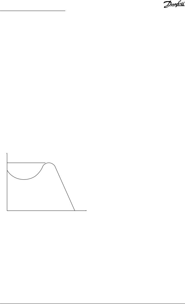
Break-away torque
Torque
Pull-out |
175ZA078.10 |
|
rpm
Illustration 1.1 Break-away Torque
ηVLT
The e‚ciency of the frequency converter is de€ned as the ratio between the power output and the power input.
Start-disable command
A stop command belonging to Group 1 control commands - see Table 1.1.
Stop command
A stop command belonging to Group 1 control commands - see Table 1.1.
Analog reference
A signal transmitted to the analog inputs 53 or 54 (voltage or current).
Binary reference
A signal transmitted to the serial communication port.
Preset reference
A de€ned preset reference to be set from -100% to +100% of the reference range. Selection of 8 preset references via the digital terminals.
Pulse reference
A pulse frequency signal transmitted to the digital inputs (terminal 29 or 33).
RefMAX
Determines the relationship between the reference input at 100% full scale value (typically 10 V, 20 mA) and the resulting reference. The maximum reference value is set in parameter 3-03 Maximum Reference.
RefMIN
Determines the relationship between the reference input at 0% value (typically 0 V, 0 mA, 4 mA) and the resulting reference. The minimum reference value is set in
parameter 3-02 Minimum Reference.
1.6.5 Miscellaneous
Analog inputs
The analog inputs are used for controlling various functions of the frequency converter.
There are 2 types of analog inputs: Current input, 0–20 mA, and 4–20 mA Voltage input, -10 V DC to +10 V DC.
Analog outputs
The analog outputs can supply a signal of 0–20 mA, 4–20 mA.
Automatic motor adaptation, AMA
AMA algorithm determines the electrical parameters for the connected motor at standstill.
Brake resistor
The brake resistor is a module capable of absorbing the brake power generated in regenerative braking. This regenerative brake power increases the DC-link voltage and a brake chopper ensures that the power is transmitted to the brake resistor.
CT characteristics
Constant torque characteristics used for all applications such as conveyor belts, displacement pumps, and cranes.
Digital inputs
The digital inputs can be used for controlling various functions of the frequency converter.
MG20OA02 |
Danfoss A/S © 05/2016 All rights reserved. |
5 |

Introduction |
VLT® AQUA Drive FC 202 |
1 1 Digital outputs
The frequency converter features 2 solid-state outputs that can supply a 24 V DC (maximum 40 mA) signal.
DSP
Digital signal processor.
ETR
Electronic thermal relay is a thermal load calculation based on present load and time. Its purpose is to estimate the motor temperature.
Hiperface®
Hiperface® is a registered trademark by Stegmann.
Initializing
If initializing is carried out (parameter 14-22 Operation Mode), the frequency converter returns to the default setting.
Intermittent duty cycle
An intermittent duty rating refers to a sequence of duty cycles. Each cycle consists of an on-load and an off-load period. The operation can be either periodic duty or nonperiodic duty.
LCP
The local control panel makes up a complete interface for control and programming of the frequency converter. The control panel is detachable and can be installed up to 3 m (10 ft) from the frequency converter, that is, in a front panel with the installation kit option.
NLCP
Numerical local control panel interface for control and programming of the frequency converter. The display is numerical and the panel is used to show process values. The NLCP has no storage and copy functions.
lsb
Least signi€cant bit.
msb
Most signi€cant bit.
MCM
Short for mille circular mil, an American measuring unit for cable cross-section. 1 MCM=0.5067 mm2.
Online/offline parameters
Changes to online parameters are activated immediately after the data value is changed. Press [OK] to activate changes to off-line parameters.
Process PID
The PID control maintains the required speed, pressure, temperature, and so on, by adjusting the output frequency to match the varying load.
PCD
Process control data.
Power cycle
Switch off the mains until display (LCP) is dark – then turn power on again.
Pulse input/incremental encoder
An external, digital pulse transmitter used for feeding back information on motor speed. The encoder is used in applications where great accuracy in speed control is required.
RCD
Residual current device.
Set-up
Save parameter settings in 4 set-ups. Change between the 4 parameter set-ups and edit 1 set-up, while another setup is active.
SFAVM
Switching pattern called stator flux-oriented asynchronous vector modulation (parameter 14-00 Switching Pattern).
Slip compensation
The frequency converter compensates for the motor slip by giving the frequency a supplement that follows the measured motor load keeping the motor speed almost constant.
SLC
The SLC (smart logic control) is a sequence of user-de€ned actions executed when the associated user-de€ned events are evaluated as true by the SLC. (See
chapter 3.12 Parameters 13-** Smart Logic).
STW
Status word.
FC standard bus
Includes RS485 bus with FC protocol or MC protocol. See parameter 8-30 Protocol.
THD
Total harmonic distortion states the total contribution of harmonic.
Thermistor
A temperature-dependent resistor placed on the frequency converter or the motor.
Trip
A state entered in fault situations, for example if the frequency converter is subject to an overtemperature or when the frequency converter is protecting the motor, process, or mechanism. The frequency converter prevents a restart until the cause of the fault has disappeared. To cancel the trip state, restart the frequency converter. Do not use the trip state for personal safety.
Trip lock
The frequency converter enters this state in fault situations to protect itself. The frequency converter requires physical intervention, for example when there is a short circuit on the output. A trip lock can only be canceled by disconnecting mains, removing the cause of the fault, and reconnecting the frequency converter. Restart is prevented until the trip state is canceled by activating reset or, sometimes, by being programmed to reset automatically. Do not use the trip lock state for personal safety.
6 |
Danfoss A/S © 05/2016 All rights reserved. |
MG20OA02 |

Introduction |
Programming Guide |
|
|
VT characteristics
Variable torque characteristics used for pumps and fans.
VVC+
If compared with standard voltage/frequency ratio control, voltage vector control (VVC+) improves the dynamics and the stability, both when the speed reference is changed and in relation to the load torque.
60° AVM
60° asynchronous vector modulation (parameter 14-00 Switching Pattern).
Power factor
The power factor is the relation between I1 and IRMS.
|
|
U x I cos |
Power factor |
= |
3 x x U x1IRMSϕ |
|
3 |
The power factor for 3-phase control:
Power factor |
= |
I |
1 |
x cos |
ϕ1 |
= |
I |
1 |
since cos |
ϕ1 = 1 |
|
|
|
RMS |
|
||||||||
|
|
|
I |
|
|
|
IRMS |
|
|||
|
|
|
|
|
|
|
|
|
|||
The power factor indicates to which extent the frequency converter imposes a load on the mains supply.
The lower the power factor, the higher the IRMS for the same kW performance.
IRMS = I21 + I25 + I27 + .. + I2n
In addition, a high-power factor indicates that the different harmonic currents are low.
The DC coils in the frequency converters produce a highpower factor, which minimizes the imposed load on the mains supply.
Target position
The €nal target position speci€ed by positioning commands. The pro€le generator uses this position to calculate the speed pro€le.
Commanded position
The actual position reference calculated by the pro€le generator. The frequency converter uses the commanded position as setpoint for position PI.
Actual position
The actual position from an encoder, or a value that the motor control calculates in open loop. The frequency converter uses the actual position as feedback for position PI.
Position error
Position error is the difference between the actual position and the commanded position. The position error is the input for the position PI controller.
Position unit
The physical unit for position values.
1.7 |
Abbreviations, Symbols, and |
|
1 |
1 |
|
|
Conventions |
|
|
|
|
|
|
|
|
|
|
|
|
|
|
|
|
°C |
|
Degrees Celsius |
|
|
|
°F |
|
Degrees Fahrenheit |
|
|
|
AC |
|
Alternating current |
|
|
|
|
|
|
|
|
|
AEO |
|
Automatic energy optimization |
|
|
|
|
|
|
|
|
|
AWG |
|
American wire gauge |
|
|
|
|
|
|
|
|
|
AMA |
|
Automatic motor adaptation |
|
|
|
|
|
|
|
|
|
DC |
|
Direct current |
|
|
|
|
|
|
|
|
|
EMC |
|
Electro magnetic compatibility |
|
|
|
|
|
|
|
|
|
ETR |
|
Electronic thermal relay |
|
|
|
|
|
|
|
|
|
fM,N |
|
Nominal motor frequency |
|
|
|
|
|
|
|
|
|
FC |
|
Frequency converter |
|
|
|
|
|
|
|
|
|
IINV |
|
Rated inverter output current |
|
|
|
|
|
|
|
|
|
ILIM |
|
Current limit |
|
|
|
|
|
|
|
|
|
IM,N |
|
Nominal motor current |
|
|
|
|
|
|
|
|
|
IVLT,MAX |
Maximum output current |
|
|
|
|
|
|
|
|
|
|
IVLT,N |
|
Rated output current supplied by the |
|
|
|
|
frequency converter |
|
|
|
|
|
|
|
|
|
|
|
|
|
|
|
|
IP |
|
Ingress protection |
|
|
|
|
|
|
|
|
|
LCP |
|
Local control panel |
|
|
|
|
|
|
|
|
|
MCT |
|
Motion control tool |
|
|
|
|
|
|
|
|
|
ns |
|
Synchronous motor speed |
|
|
|
|
|
|
|
|
|
PM,N |
|
Nominal motor power |
|
|
|
|
|
|
|
|
|
PELV |
|
Protective extra low voltage |
|
|
|
|
|
|
|
|
|
PCB |
|
Printed circuit board |
|
|
|
|
|
|
|
|
|
PM Motor |
Permanent magnet motor |
|
|
|
|
|
|
|
|
|
|
PWM |
|
Pulse width modulation |
|
|
|
|
|
|
|
|
|
RPM |
|
Revolutions per minute |
|
|
|
|
|
|
|
|
|
Regen |
Regenerative terminals |
|
|
|
|
|
|
|
|
|
|
TLIM |
|
Torque limit |
|
|
|
|
|
|
|
|
|
UM,N |
|
Nominal motor voltage |
|
|
|
|
|
|
|
|
|
1.8 |
Safety |
|
|
|
|

 WARNING
HIGH VOLTAGE
Frequency converters contain high voltage when connected to AC mains input, DC supply, or load sharing. Failure to perform installation, start-up, and maintenance by qualified personnel can result in death or serious injury.
•Only qualified personnel must perform installation, start-up, and maintenance.
Safety regulations
•Disconnect mains supply to the frequency converter whenever repair work is to be carried out. Check that the mains supply has been disconnected and that the necessary time has elapsed before removing motor and mains supply
MG20OA02 |
Danfoss A/S © 05/2016 All rights reserved. |
7 |

Introduction |
VLT® AQUA Drive FC 202 |
1 |
1 |
plugs. For information about the discharge time, |
|
|
see Table 1.2. |
|
|
•[Off] does not disconnect the mains supply and consequently, it must not be used as a safety switch.
•Ground the equipment properly. Protect the user against supply voltage and protect the motor against overload in accordance with applicable national and local regulations.
•The ground leakage current exceeds 3.5 mA.
•Protection against motor overload is not included in the factory setting. If this function is required, set parameter 1-90 Motor Thermal Protection to data value [4] ETR trip 1 or data value [3] ETR warning 1.
•Do not remove the plugs for the motor and mains supply while the frequency converter is connected to mains. Check that the mains supply has been disconnected and that the necessary time has elapsed before removing motor and mains plugs.
•The frequency converter has more voltage sources than L1, L2, and L3, when load sharing (linking of DC-link) or
external 24 V DC is installed. Check that all voltage sources have been disconnected and that the necessary time has elapsed before commencing repair work. For information about the discharge time, see Table 1.2.

 WARNING
UNINTENDED START
When the frequency converter is connected to AC mains, DC supply, or load sharing, the motor may start at any time. Unintended start during programming, service, or repair work can result in death, serious injury, or property damage. The motor can start via an external switch, a fieldbus command, an input reference signal from the LCP, or after a cleared fault condition.
To prevent unintended motor start:
•Disconnect the frequency converter from the mains.

 WARNING
DISCHARGE TIME
The frequency converter contains DC-link capacitors, which can remain charged even when the frequency converter is not powered. Failure to wait the specified time after power has been removed before performing service or repair work, could result in death or serious injury.
1.Stop the motor.
2.Disconnect the AC mains, permanent magnet type motors, and remote DC-link power supplies, including battery back-ups, UPS, and DC-link connections to other frequency converters.
3.Wait for the capacitors to discharge fully before performing any service or repair work. The duration of waiting time is specified in Table 1.2.
Voltage [V] |
Minimum waiting time (minutes) |
||
|
|
|
|
|
4 |
7 |
15 |
|
|
|
|
200–240 |
0.25–3.7 kW |
– |
5.5–45 kW |
|
(0.34–5 hp) |
|
(7.5–60 hp) |
|
|
|
|
380–480 |
0.37–7.5 kW |
– |
11–90 kW |
|
(0.5–10 hp) |
|
(15–121 hp) |
|
|
|
|
525–600 |
0.75–7.5 kW |
– |
11–90 kW |
|
(1–10 hp) |
|
(15–121 hp) |
|
|
|
|
525–690 |
– |
1.1–7.5 kW |
11–90 kW |
|
|
(1.5–10 hp) |
(15–121 hp) |
|
|
|
|
High voltage may be present even when the warning LED indicator lights are off.
Table 1.2 Discharge Time
•Press [Off/Reset] on the LCP before programming parameters.
•Completely wire and assemble the frequency converter, motor, and any driven equipment before connecting the frequency converter to AC mains, DC supply, or load sharing.
8 |
Danfoss A/S © 05/2016 All rights reserved. |
MG20OA02 |
Introduction |
Programming Guide |
|
|
NOTICE
When using Safe Torque Off, always follow the instructions in VLT® Frequency Converters - Safe Torque
O€ Operating Instructions.
NOTICE
Control signals from or within the frequency converter may in rare cases be activated in error, be delayed, or fail to occur entirely. When used in situations where safety is critical, these control signals must not be relied on exclusively.
Protection mode |
1 1 |
Once a hardware limit on motor current or DC-link voltage is exceeded, the frequency converter enters the protection mode. Protection mode means a change of the PWM modulation strategy and a low switching frequency to minimize losses. This continues for 10 s after the last fault and increases the reliability and the robustness of the frequency converter while re-establishing full control of the motor.
NOTICE
Hazardous situations must be identified by the machine builder/integrator who is responsible for taking necessary preventive means into consideration. More monitoring and protective devices may be included, always according to valid national safety regulations, for example, law on mechanical tools, regulations for the prevention of accidents.
MG20OA02 |
Danfoss A/S © 05/2016 All rights reserved. |
9 |
|
|
|
Introduction |
VLT® AQUA Drive FC 202 |
|
|
|
|
|
1 |
1 |
|
1.9 Electrical Wiring |
|
|
|
|
1.9.1 Electrical Wiring - Control Cables |
|
|
|
|
||
3-phase power
input
DC bus
+10 VDC
0-10 VDC 0/4-20 mA
0-10 VDC 0/4-20 mA
91 |
(L1) |
|
92 |
(L2) |
|
93 |
(L3) |
|
95 |
PE |
|
88 |
(-) |
|
89 |
(+) |
|
50 |
(+10 V OUT) |
|
53 |
(A IN) |
S201 |
1 |
||
|
|
2 |
|
|
S202 |
54 |
(A IN) |
1 |
2 |
||
55 |
(COM A IN) |
|
12 |
(+24 V OUT) |
|
13 |
(+24 V OUT) |
|
 18 (D IN)
19 (D IN)
20 (COM D IN)
27 (D IN/OUT)
29 (D IN/OUT)
 32 (D IN)
33 (D IN)
*
37 (D IN)
|
|
|
|
|
|
|
|
|
|
|
|
|
|
|
|
|
|
|
|
|
|
|
|
|
|
|
|
|
|
|
|
|
|
|
|
|
|
|
|
|
|
|
|
|
|
|
|
|
|
|
|
|
|
|
|
|
|
|
|
|
|
|
|
|
|
|
|
|
|
|
|
|
|
|
|
|
|
|
|
|
|
|
|
|
|
|
|
|
|
|
|
|
|
|
|
|
|
|
|
|
|
|
|
|
|
|
|
|
|
|
|
|
|
|
|
|
|
|
|
|
|
|
|
|
|
|
|
|
|
|
|
|
|
|
|
|
|
|
|
|
|
|
|
|
|
|
|
|
|
|
|
|
|
|
|
|
|
|
|
|
|
|
|
|
|
|
|
|
|
|
|
|
|
|
|
|
|
|
|
|
|
|
|
|
|
|
|
|
|
|
|
|
|
|
|
|
|
|
|
|
|
|
|
|
|
|
|
|
|
|
|
|
|
|
|
|
|
|
|
|
|
|
|
|
|
|
|
|
|
|
|
|
|
|
|
|
|
|
|
|
|
|
|
|
|
|
|
|
|
|
|
|
|
|
|
|
|
|
|
|
|
|
|
|
|
|
|
|
|
|
|
|
|
|
|
|
|
|
|
|
|
|
|
|
|
|
|
|
|
|
|
|
|
|
|
|
|
|
|
|
|
|
|
|
|
|
|
|
|
|
|
|
|
|
|
|
|
|
|
|
|
|
|
|
|
|
|
|
|
|
|
|
|
|
|
|
|
|
|
|
|
|
|
|
|
|
|
|
|
|
|
|
|
|
|
|
|
|
|
|
|
|
|
|
|
|
|
|
|
|
|
|
|
|
|
|
Switch Mode |
|
|
|
|
|
|
|
|
|
|
||||||||
|
|
|
|
|
|
|
|
|
|
|
|
|
|
|
|
|
|
||||||||||||||||||
|
|
|
|
|
|
|
|
|
|
|
|
|
|
Power Supply |
|
|
|
|
|
|
|
|
|
|
|||||||||||
|
|
|
|
|
|
|
|
|
|
|
|
|
|
|
|
|
|
|
|
|
|
|
24 VDC |
|
|
|
|
|
|
||||||
|
|
|
|
|
|
|
|
|
|
|
|
|
|
15 mA |
|
|
200 mA |
|
|
|
|
|
|||||||||||||
|
|
|
|
|
|
|
|
|
|
|
|
|
+ |
|
- |
|
|
+ |
|
|
|
- |
|
|
|
|
|
|
|
|
|
||||
|
|
|
|
|
|
|
|
|
|
|
|
|
|
|
|
|
|
|
|
|
|
|
|
|
|
|
|
|
|||||||
|
|
|
|
|
|
|
|
|
|
|
|
|
|
|
|
|
|
|
|
|
|
|
|
|
|
|
|
|
|
|
|
|
|
||
ON |
|
|
ON=0-20 mA |
|
|
|
|
|
|
|
|
|
|
|
|
|
|
|
|
||||||||||||||||
|
|
|
|
|
|
|
|
|
|
|
|
|
|
|
|
|
|
|
|
||||||||||||||||
ON |
|
|
OFF=0-10 V |
|
|
|
|
|
|
|
|
|
|
|
|
|
|
|
|
||||||||||||||||
|
|
|
|
|
|
|
|
|
|
|
|
|
|
|
|
|
|
|
|
|
|
|
|
|
|
|
|
|
|
|
|
|
|
||
|
|
|
|
|
|
|
|
|
|
|
|
|
|
|
|
|
|
|
|
|
|
|
|
|
|
|
|
|
|
|
|
|
|
|
|
|
|
|
|
|
|
|
|
|
|
|
|
|
|
|
|
|
|
|
|
|
|
|
|
|
|
|
|
|
|
|
|
|
|
|
|
|
|
|
|
|
|
|
|
|
|
P 5-00 |
|
|
|
|
|
|
|
|
|
|
|
|
|
|
|
||||||||||
|
|
|
|
|
|
|
|
|
|
|
|
|
|
|
|
|
|
|
|
|
|
|
|
|
|||||||||||
|
|
|
|
|
|
|
|
|
|
|
|
|
|
|
|
|
|
|
|
|
|
|
|
|
|||||||||||
|
|
|
|
|
|
|
|
|
|
|
|
|
|
|
|
|
24 V (NPN) |
|
|
|
|
|
|
|
|
|
|
||||||||
|
|
|
|
|
|
|
|
|
|
|
|
|
|
|
|
|
0 V (PNP) |
|
|
|
|
|
|
|
|
|
|
||||||||
|
|
|
|
|
|
|
|
|
|
|
|
|
|
|
|
|
|
|
|
|
|
|
|
|
|
|
|||||||||
|
|
|
|
|
|
|
|
|
|
|
|
|
|
|
|
|
24 V (NPN) |
|
|
|
|
|
|
|
|
|
|
||||||||
|
|
|
|
|
|
|
|
|
|
|
|
|
|
|
|
|
0 V (PNP) |
|
|
|
|
|
|
|
|
|
|
||||||||
|
|
|
|
|
|
|
|
|
|
|
|
|
|
|
|
|
|
|
|
|
|
|
|
|
|
|
|||||||||
|
|
|
|
|
|
|
|
|
|
|
|
|
|
|
|
|
24 V (NPN) |
|
|
|
|
S801 |
|
||||||||||||
|
|
|
|
24V |
|
|
|
|
|
|
|
|
|
0 V (PNP) |
|
|
|
|
|
||||||||||||||||
|
|
|
|
|
|
|
|
|
|
|
|
|
|
|
|
|
|
|
|
|
|
|
|
|
|
|
2 1 |
|
|
ON |
|||||
|
|
|
|
|
|
|
|
|
|
|
|
|
|
|
|
|
|
|
|
|
|
|
|
|
|
|
|
|
|||||||
|
|
|
0V |
|
|
|
|
|
|
|
|
|
24 V (NPN) |
|
|
|
|
|
|
|
5V |
|
|||||||||||||
|
|
|
|
|
|
|
|
|
|
|
|
|
|
|
|
|
|
|
|
||||||||||||||||
|
|
|
|
|
|
|
|
|
|
|
|
|
|
|
|
|
|
|
|
|
|
|
|
|
|
|
|||||||||
|
|
|
|
24V |
|
|
|
|
|
|
|
|
|
0 V (PNP) |
|
|
|
|
|
|
|
|
|
|
|||||||||||
|
|
|
|
|
|
|
|
|
|
|
|
|
|
|
|
|
|
|
|
|
|
|
|||||||||||||
|
|
|
|
|
|
|
|
|
|
|
|
|
|
|
|
|
|
|
|
|
|
|
|
|
|
|
|
|
|
|
|
||||
|
|
|
0V |
|
|
|
|
|
|
|
|
|
|
|
|
|
|
|
|
|
|
|
|
|
RS-485 |
|
|||||||||
|
|
|
|
|
|
|
|
|
|
|
|
|
|
|
|
|
|
|
|
|
|
|
|
|
|||||||||||
|
|
|
|
|
|
|
|
|
|
|
|
|
|
|
|
|
|
|
|
|
|
|
|
|
|||||||||||
|
|
|
|
|
|
|
|
|
|
|
|
|
|
|
|
|
|
|
|
|
|
|
|
|
|
|
|
|
|
||||||
|
|
|
|
|
|
|
|
|
|
|
|
|
|
|
|
|
24 V (NPN) |
|
|
|
Interface |
||||||||||||||
|
|
|
|
|
|
|
|
|
|
|
|
|
|
|
|
|
0 V (PNP) |
|
|
|
|
|
|
|
|
|
|
||||||||
|
|
|
|
|
|
|
|
|
|
|
|
|
|
|
|
|
|
|
|
|
|
|
|
|
|
|
|||||||||
|
|
|
|
|
|
|
|
|
|
|
|
|
|
|
|
|
24 V (NPN) |
|
|
|
|
|
|
|
|
|
|
||||||||
|
|
|
|
|
|
|
|
|
|
|
|
|
|
|
|
|
0 V (PNP) |
|
|
|
|
|
|
|
|
|
|
||||||||
|
|
|
|
|
|
|
|
|
|
|
|
|
|
|
|
|
|
|
|
|
|
|
|
|
|
|
|||||||||
(U) 96 
(V) 97 
(W) 98 
(PE) 99 


 Motor
Motor
|
(R+) 82 |
Brake |
|
|
resistor |
|
(R-) 81 |
|
|
relay1 |
|
|
03 |
|
|
02 |
240 VAC, 2 A |
|
|
|
|
01 |
|
|
relay2 |
|
|
06 |
240 VAC, 2 A |
|
|
|
|
05 |
400 VAC, 2 A |
|
|
|
|
04 |
|
|
(COM A OUT) 39 |
Analog Output |
|
(A OUT) 42 |
0/4-20 mA |
|
|
|
ON=Terminated |
|
|
OFF=Open |
|
|
S801 |
0 V |
|
|
|
|
|
(P RS-485) 68 |
RS-485 |
|
(N RS-485) 69 |
|
(COM RS-485) 61 |
|
|
|
|
(PNP) = Source |
|
|
(NPN) = Sink |
130BE257.01
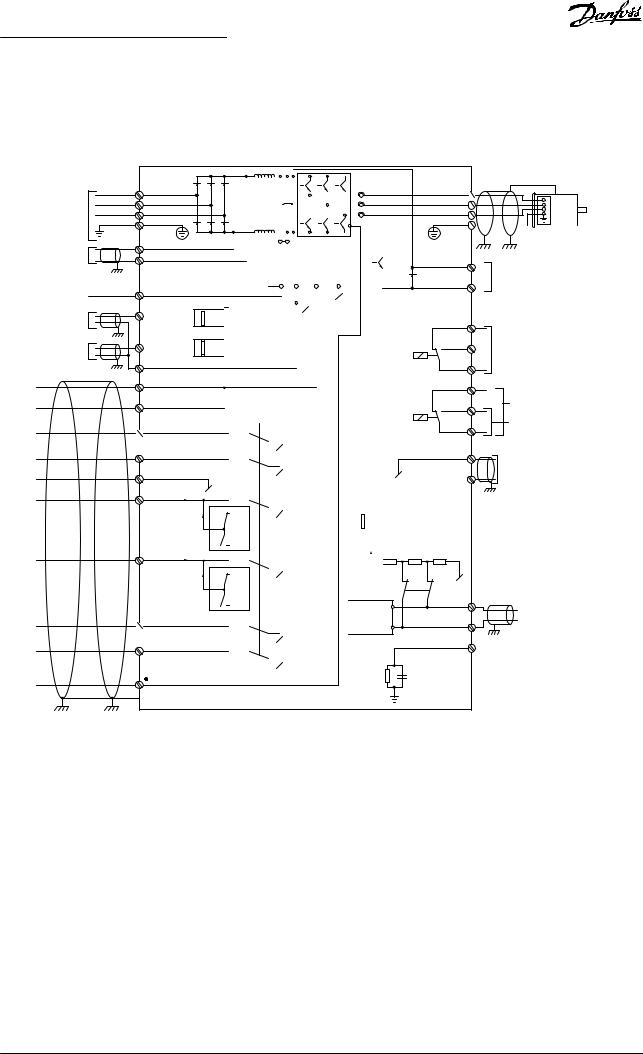
Illustration 1.2 Basic Wiring Schematic Drawing
A = Analog, D = Digital
Terminal 37 is used for Safe Torque Off. For Safe Torque Off installation instructions, refer to the VLT® Frequency Converters - Safe Torque Off Operating Instructions.
* Terminal 37 is not included in FC 202 (except enclosure size A1). Relay 2 and terminal 29 have no function in VLT® AQUA Drive FC 202.
Very long control cables and analog signals may in rare cases, and depending on installation, result in 50/60 Hz ground loops due to noise from mains supply cables.
If this occurs, it may be necessary to break the shield or insert a 100 nF capacitor between shield and enclosure.
Connect the digital and analog inputs and outputs separately to the common inputs (terminals 20, 55, and 39) of the frequency converter to avoid ground currents from both groups to affect other groups. For example, switching on the digital input may disturb the analog input signal.
10 |
Danfoss A/S © 05/2016 All rights reserved. |
MG20OA02 |
Introduction |
|
|
|
|
|
|
Programming Guide |
|
||
Input polarity of control terminals |
|
|
VDC0 |
130BT106.10 |
130BA681.10 |
|||||
VDC+24 |
|
|
PNP (Source) |
|
|
|
||||
|
|
|
|
|
|
|
|
|
||
|
|
|
Digital input wiring |
|
|
|
|
|
|
|
12 |
13 |
18 |
19 |
27 |
29 |
32 |
33 |
20 |
37 |
|
Illustration 1.3 PNP (Source)
+24VDC |
|
|
|
NPN (Sink) |
|
|
|
|
|
|
|
|
|
VDC0 |
|
130BT107.11 |
|
|||
|
|
|
|
Digital input wiring |
|
|
|
|
|
|
|
|
|
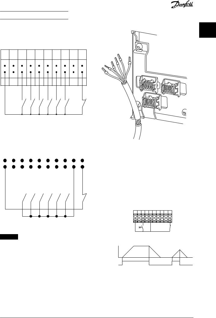
Illustration 1.5 Grounding of Shielded/Armored Control Cables |
||||||
|
|
|
|
|
|
|
|
|
|
|
|
|
|
|
|
|
|
|
|
|
12 |
13 |
18 |
|
19 |
|
27 |
|
29 |
32 |
33 |
20 |
37 |
|
|
||||||
|
|
|
|
|
|
|
|
|
|
|
|
|
|
|
|
|
|
|
|
1.9.2 Start/Stop |
|
|
|
|
|
|
|
|
|
|
|
|
|
|
|
|
|
|
|
|
|
|
|
|
|
|
|
|
|
|
|
|
|
|
|
|
|
|
|
|
|
Terminal 18 = Parameter 5-10 Terminal 18 Digital Input [8] |
|
|
|
|
|
|
|
|
|
|
|
|
|
|
|
|
|
|
|
|
|
|
|
|
|
|
|
|
|
|
|
|
|
|
|
|
|
|
|
|
|
Start. |
|
|
|
|
|
|
|
|
|
|
|
|
|
|
|
|
|
|
|
|
|
|
|
|
|
|
|
|
|
|
|
|
|
|
|
|
|
|
|
|
|
Terminal 27 = Parameter 5-12 Terminal 27 Digital Input [0] |
|
|
|
|
|
|
|
|
|
|
|
|
|
|
|
|
|
|
|
|
No operation (Default [2] Coast inverse). |
|
|
|
|
|
|
|
|
|
|
|
|
|
|
|
|
|
|
|
|
Terminal 37 = Safe Torque Off (where available). |
|
|
|
|
|
|
|
|
|
|
|
|
|
|
|
|
|
|
|
|
|
Illustration 1.4 NPN (Sink)
NOTICE
+24V P 5-10 [8] |
P 5-12 [0] |
12 13 18 19 27 29 32 33 20 37
Start/Stop |
Safe Stop |
130BA155.12
Control cables must be shielded/armored.
Speed
See section Grounding of Shielded Control Cables in the design guide for the correct termination of control cables.
Start/Stop
[18]
Illustration 1.6 Start/Stop
1 1
MG20OA02 |
Danfoss A/S © 05/2016 All rights reserved. |
11 |
|
|
Introduction |
VLT® AQUA Drive FC 202 |
|
|
|
|
1 |
1 |
1.9.3 Pulse Start/Stop |
|
|
|
|
|
Terminal 18 = Parameter 5-10 Terminal 18 Digital Input [9]
Latched start.
Terminal 27 = Parameter 5-12 Terminal 27 Digital Input [6]
Stop inverse.
Terminal 37 = Safe Torque Off (where available).
+24V |
|
P 5 - 10[9] |
|
P 5 - 12 [6] |
|
|
|
|
|
130BA156.12 |
12 |
13 |
18 |
19 |
27 |
29 |
32 |
33 |
20 |
37 |
|
|
|
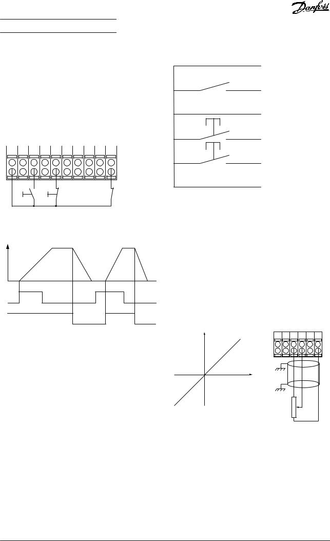
Illustration 1.8 Speed Up/Down |
Start |
Stop inverse |
Safe Stop |
12 |
+24V |
|
|
18 |
Par. 5-10 |
|
|
27 |
Par. 5-12 |
|
|
29 |
Par. 5-13 |
|
|
32 |
Par. 5-14 |
|
|
37 |
|
|
|
130BA021.12
Speed
Start (18)
Start (27)
Illustration 1.7 Pulse Start/Stop
1.9.4 Speed Up/Down
Terminals 29/32 = Speed up/down
Terminal 18 = Parameter 5-10 Terminal 18 Digital Input [9] Start (default).
Terminal 27 = Parameter 5-12 Terminal 27 Digital Input [19] Freeze reference.
Terminal 29 = Parameter 5-13 Terminal 29 Digital Input [21] Speed up.
Terminal 32 = Parameter 5-14 Terminal 32 Digital Input [22] Speed down.
1.9.5 Potentiometer Reference
Voltage reference via a potentiometer
Reference source 1 = [1] Analog input 53 (default). Terminal 53, Low Voltage = 0 V.
Terminal 53, High Voltage = 10 V. Terminal 53, Low Ref./Feedback = 0 RPM.
Terminal 53, High Ref./Feedback = 1500 RPM. Switch S201 = OFF (U).
Speed RPM |
P 6-15 |
Ref. voltage |
P 6-11 10V |
|
|
+10V/30mA |
|
|
130BA154.11 |
39 |
42 |
50 |
53 |
54 |
55 |
|
1 k |
|
|
|
|
Illustration 1.9 Potentiometer Reference
12 |
Danfoss A/S © 05/2016 All rights reserved. |
MG20OA02 |
How to Program |
Programming Guide |
|
|
2 How to Program
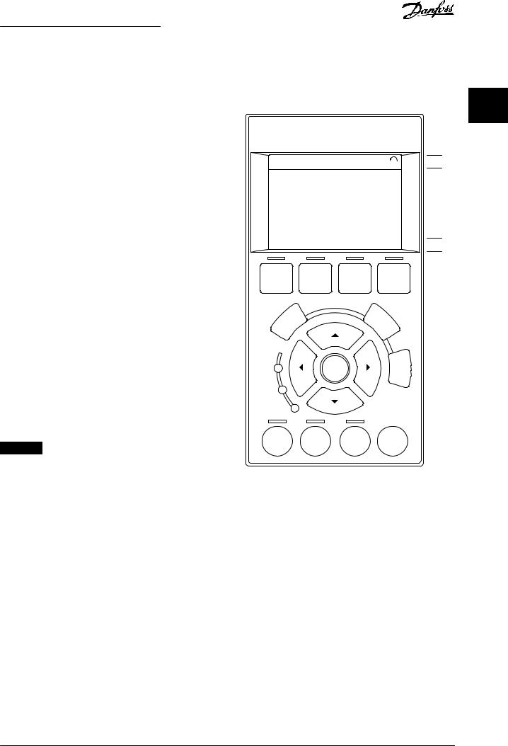
2.1The Graphical and Numerical Local Control Panel
Easy programming of the frequency converter is done via the graphical LCP (LCP 102). Consult the frequency converter design guide when using the numeric local control panel (LCP 101).
2.2 How to Program on the Graphical LCP
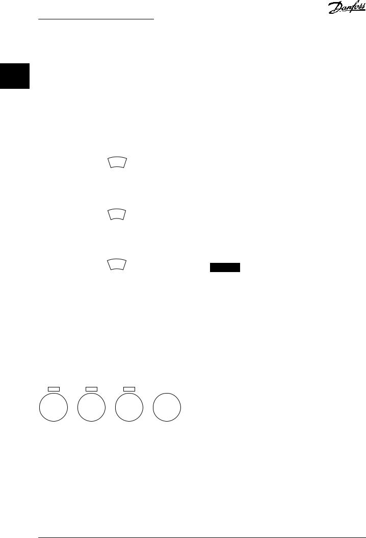
The LCP is divided into 4 functional groups:
1.Graphical display with status lines.
2.Menu keys and indicator lights - changing parameters and switching between display functions.
3.Navigation keys and indicator lights.
4.Operation keys and indicator lights.
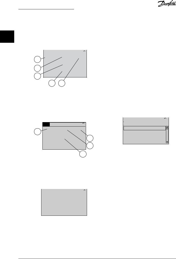
The LCP display can show up to 5 items of operating data while showing Status.
Display lines:
a.Status line: Status messages showing icons and graphics.
b.Line 1–2: Operator data lines showing data de€ned or selected. Add up to 1 extra line by pressing [Status].
c.Status line: Status messages showing text.
NOTICE
If start-up is delayed, the LCP shows the INITIALIZING message until it is ready. Adding or removing options can delay the start-up.
|
Status |
|
|
1(0) |
|
|
1234rpm |
|
10,4A |
43,5Hz |
|
1 |
|
43,5Hz |
|
||
|
|
|
|||
|
Run OK |
|
|
|
|
2 |
Status |
Quick |
Main |
Alarm |
|
Menu |
Menu |
Log |
|||
|
|
||||
|
Back |
|
|
Cancel |
|
|
|
|
|
||
3 |
On |
|
OK |
Info |
|
|
Warn. |
|
|
|
|
|
Alarm |
|
|
|
|
4 |
Hand |
O |
Auto |
Reset |
|
on |
on |
||||
|
|
|
|||
Illustration 2.1 LCP
2 2
130BA018.13
a
b
c
MG20OA02 |
Danfoss A/S © 05/2016 All rights reserved. |
13 |
How to Program |
VLT® AQUA Drive FC 202 |
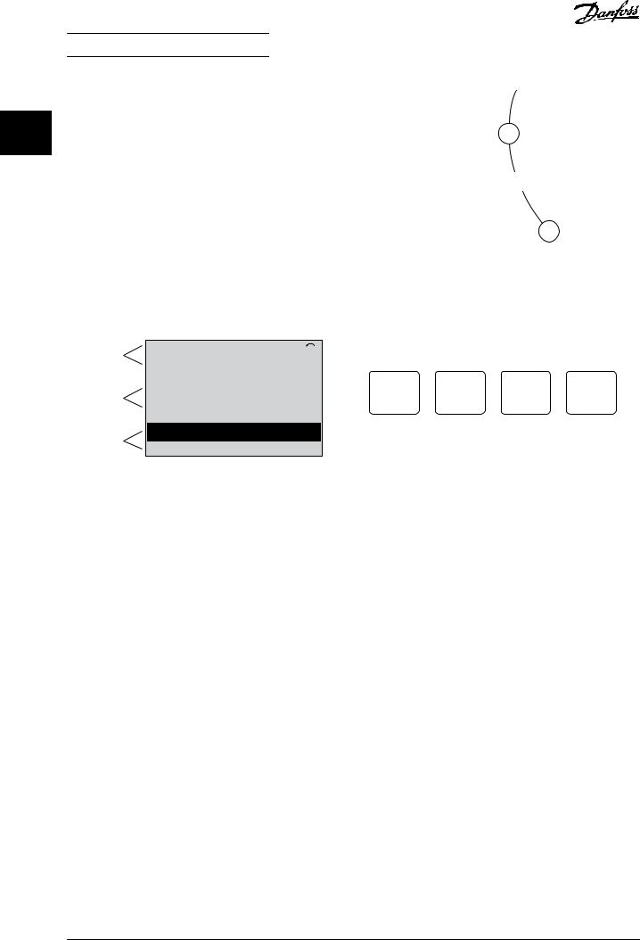
2.2.1 The LCP Display
2 2 The LCP display has backlight and a total of 6 alphanumeric lines. The display lines show the direction of rotation (arrow), the selected set-up, and the programming set-up. The display is divided into 3 sections.
Top section
Shows up to 2 measurements in normal operating status.
Middle section
The top line shows up to 5 measurements with related units, regardless of status (except in the case of alarm/ warning).
On
Warn. 
Alarm
Illustration 2.3 Indicator Lights
130BP044.10
Bottom section
Always shows the state of the frequency converter in
Status mode.
Top section |
Status |
|
! 1(1) |
|
|
|
|
|
43 RPM |
5.44 A |
25.3kW |
1.4 Hz
Middle section
2.9%
! Pwr.card temp (W29)
Bottom section
Auto Remote Running
130BP074.10
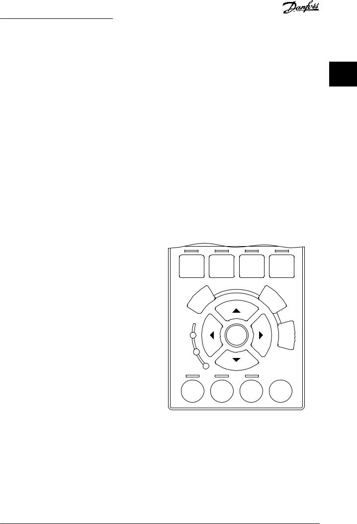
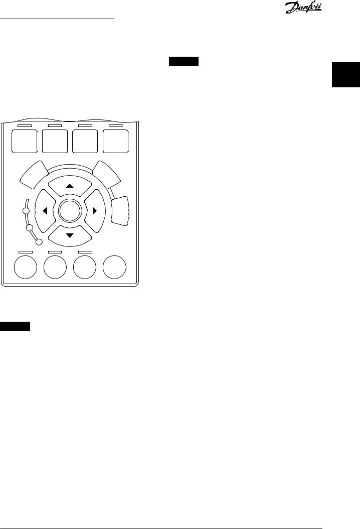
LCP keys
The control keys are divided into functions. The keys below the display and indicator lights are used for parameter setup, including the option of display indication during normal operation.
Status |
Quick |
Main |
Alarm |
130BP045.10 |
|
||||
Menu |
Menu |
Log |
|
|
|
|
Illustration 2.4 LCP Keys
Illustration 2.2 Bottom Section
The active set-up (selected as the active set-up in parameter 0-10 Active Set-up) is shown. When programming another set-up than the active set-up, the number of the programmed set-up appears to the right.
Display contrast adjustment
Press [Status] and [▲] for darker display. Press [Status] and [▼] for brighter display.
Most parameter set-ups can be changed immediately via the LCP, unless a password has been created via parameter 0-60 Main Menu Password or via
parameter 0-65 Personal Menu Password.
Indicator lights
If certain threshold values are exceeded, the alarm and/or warning indicator lights up. A status and an alarm text appear on the LCP.
The ON indicator light is activated when the frequency converter receives mains voltage, or via a DC bus terminal, or 24 V external supply. At the same time, the backlight is on.
•Green LED/On: Control section is working.
•Yellow LED/Warn.: Indicates a warning.
•Flashing red LED/Alarm: Indicates an alarm.
[Status]
Indicates the status of the frequency converter and/or the motor. Select between 3 different readouts by pressing [Status]: 5-line readouts, 4-line readouts, or smart logic control.
Press [Status] for selecting the mode of display or for changing back to display mode from either the Quick Menu mode, the Main Menu mode, or Alarm mode. Also use [Status] to toggle single or double readout mode.
[Quick Menu]
Provides quick access to the most common functions of the frequency converter.
The [Quick Menu] consists of:
•Q1: My personal menu.
•Q2: Quick set-up.
•Q3: Function set-ups.
•Q4: Smart start.
•Q5: Changes made.
•Q6: Loggings.
•Q7: Water and pumps.
The function set-up provides quick access to all parameters required for most water and wastewater applications including:
•Variable torque.
•Constant torque.
•Pumps.
14 |
Danfoss A/S © 05/2016 All rights reserved. |
MG20OA02 |
How to Program |
Programming Guide |
|
|
•Dosing pumps.
•Well pumps.
•Booster pumps.
•Mixer pumps.
•Aeration blowers.
•Other pump.
•Fan applications.
Among other features, it also includes parameters for selecting the following:
•Which variables to show on the LCP.
•Digital preset speeds.
•Scaling of analog references.
•Closed-loop single-zone and multi-zone applications.
•Speci€c functions related to water.
•Wastewater applications.
The quick menu Q7: Water and Pumps provides direct access to some of the most important dedicated water and pump features:
•Q7-1: Special ramps (initial ramp, €nal ramp, check valve ramp).
•Q7-2: Sleep mode.
•Q7-3: Deragging.
•Q7-4: Dry Run.
•Q7-5: End of Curve Detection.
•Q7-6: Flow Compensation.
•Q7-7: Pipe Fill (Horizontal Pipes, Vertical Pipes, Mixed Systems).
•Q7-8: Control Performance.
•Q7-9: Min. Speed Monitor.
The Quick Menu parameters can be accessed immediately, unless a password was created via 1 of the following parameters:
Parameter 0-60 Main Menu Password.
• |
Parameter 0-60 |
Main Menu Password. |
|
• |
Parameter 0-61 |
Access to Main Menu w/o Password. |
2 2 |
• |
Parameter 0-65 |
Personal Menu Password. |
•Parameter 0-66 Access to Personal Menu w/o Password.
For most water and wastewater applications, it is not necessary to access the Main Menu parameters. The Quick Menu, quick set-up, and function set-ups provide the simplest and quickest access to the typical required parameters.
It is possible to switch directly between Main Menu mode and Quick Menu mode.
Parameter shortcut can be created by pressing [Main Menu] for 3 s. The parameter shortcut allows direct access to any parameter.
[Alarm Log]
Shows an alarm list of the 5 latest alarms (numbered A1– A5). To obtain more details about an alarm, press the navigation keys to navigate to the alarm number and press [OK]. Just before entering the alarm mode, information about the condition of the frequency converter is provided.
Status |
Quick |
Main |
Alarm |
130BA027.10 |
|
Menu |
Menu |
Log |
|
|
Back |
Cancel |
|
|
|
On |
OK |
Info |
Warn. |
|
|
Alarm |
|
|
Parameter 0-61 |
Access to Main Menu w/o Password. |
Hand |
O |
Auto |
Reset |
|
on |
on |
|||||
|
|
|
|
|||
Parameter 0-65 |
Personal Menu Password. |
|
|
|
|
|
Parameter 0-66 |
Access to Personal Menu w/o |
Illustration 2.5 LCP |
|
|
|
|
Password. |
|
|
|
|
||
|
|
|
|
|
It is possible to switch directly between Quick Menu mode and Main Menu mode.
[Main Menu]
This section is used for programming all parameters. The Main Menu parameters can be accessed immediately
unless a password has been created via 1 of the following parameters:
MG20OA02 |
Danfoss A/S © 05/2016 All rights reserved. |
15 |
How to Program |
VLT® AQUA Drive FC 202 |
[Back]
Reverts to the previous step or layer in the navigation 2 2 structure.
[Cancel]
Last change or command is canceled as long as the display has not been changed.
[Info]
Supplies information about a command, parameter, or function in any display window. [Info] provides detailed information whenever help is needed.
Exit info mode by pressing either [Info], [Back], or [Cancel].
The following control signals are still active when [Hand On] is activated:
•[Hand on] - [Off] - [Auto On].
•Reset.
•Coast stop inverse.
•Reversing.
•Set-up select bit 0 - Set-up select bit 1.
•Stop command from serial communication.
•Quick stop.
•DC brake.
Back
Illustration 2.6 Back
[Off]
Stops the connected motor. The key can be selected as [1] Enable or [0] Disable via parameter 0-41 [Off] Key on LCP. If no external stop function is selected and the [Off] key is inactive, stop the motor by disconnecting the voltage.
Ca |
n |
cel |
|
Illustration 2.7 Cancel
Info
Illustration 2.8 Info
[Auto On]
Enables control of the frequency converter via the control terminals and/or serial communication. When a start signal is applied on the control terminals and/or the €eldbus, the frequency converter starts. The key can be selected as [1] Enable or [0] Disable via parameter 0-42 [Auto on] Key on LCP.
NOTICE
An active HAND-OFF-AUTO signal via the digital inputs has higher priority than the control keys [Hand On] and [Auto On].
Navigation keys
The 4 navigation keys are used to navigate between the different options available in Quick Menu, Main Menu and Alarm Log. Press the keys to move the cursor.
[OK]
Is used for selecting a parameter marked by the cursor and for enabling the change of a parameter.
Local control keys
Local control keys are at the bottom of the LCP.
[Reset]
Is used for resetting the frequency converter after an alarm (trip). It can be selected as [1] Enable or [0] Disable via parameter 0-43 [Reset] Key on LCP.
The parameter shortcut can be created by pressing [Main Menu] for 3 s. The parameter shortcut allows direct access to any parameter.
Hand |
O |
Auto |
Reset |
|
on |
on |
|||
|
|
130BP046.10
Illustration 2.9 Local Control Keys
[Hand On]
Enables control of the frequency converter via the LCP. [Hand On] also starts the motor, and it is now possible to enter the motor speed data with the navigation keys. The key can be selected as [1] Enable or [0] Disable via parameter 0-40 [Hand on] Key on LCP.
External stop signals activated with control signals, or a €eldbus, override a start command via the LCP.
16 |
Danfoss A/S © 05/2016 All rights reserved. |
MG20OA02 |
How to Program |
Programming Guide |
|
|
2.2.2Quick Transfer of Parameter Settings between Multiple Frequency Converters
Once the set-up of a frequency converter is complete, store the data in the LCP or on a PC via MCT 10 Set-up Software.
Status |
Quick |
Main |
Alarm |
130BA027.10 |
|
Menu |
Menu |
Log |
|
|
Back |
Cancel |
|
|
|
On |
OK |
Info |
Warn.
Alarm
Hand |
O |
Auto |
Reset |
|
on |
on |
|||
|
|
Illustration 2.10 LCP
Data storage in LCP
NOTICE
Stop the motor before performing this operation.
To store the data in the LCP:
1.Go to parameter 0-50 LCP Copy.
2.Press the [OK] key.
3.Select [1] All to LCP.
4.Press the [OK] key.
All parameter settings are now stored in the LCP indicated by the progress bar. When 100% is reached, press [OK].
Connect the LCP to another frequency converter and copy the parameter settings to this frequency converter as well.
Data transfer from LCP to frequency converter
NOTICE
Stop the motor before performing this operation. |
2 |
2 |
|
To transfer the data from the LCP to the frequency |
|||
converter: |
|
|
|
1. |
Go to parameter 0-50 LCP Copy. |
|
|
2. |
Press the [OK] key. |
|
|
3. |
Select [2] All from LCP. |
|
|
4. |
Press the [OK] key. |
|
|
The parameter settings stored in the LCP are now transferred to the frequency converter indicated by the progress bar. When 100% is reached, press [OK].
2.2.3 Display Mode
In normal operation, up to 5 different operating variables can be indicated continuously in the middle section: 1.1, 1.2, and 1.3, as well as 2 and 3.
2.2.4 Display Mode - Selection of Readouts
Press [Status] to toggle between 3 status readout screens. Operating variables with different formatting are shown in each status screen. For more information, see the examples in this chapter.
Several values or measurements can be linked to each of the shown operating variables. The values or measurements to be shown can be de€ned via the following parameters:
•Parameter 0-20 Display Line 1.1 Small.
•Parameter 0-21 Display Line 1.2 Small.
•Parameter 0-22 Display Line 1.3 Small.
•Parameter 0-23 Display Line 2 Large.
•Parameter 0-24 Display Line 3 Large.
Access the parameters via [Quick Menu], Q3 Function Setups, Q3-1 General Settings, Q3-13 Display Settings.
Each readout parameter selected in parameter 0-20 Display Line 1.1 Small to parameter 0-24 Display Line 3 Large has its own scale and digits after a decimal point. The higher numeric value of a parameter, the fewer digits are shown after the decimal point.
Example: Current readout 5.25 A; 15.2 A; 105 A.
See parameter group 0-2* LCP Display for further details.
MG20OA02 |
Danfoss A/S © 05/2016 All rights reserved. |
17 |
How to Program |
VLT® AQUA Drive FC 202 |
Status screen I
This readout state is standard after start-up or initialization. 2 2 Press [Info] to obtain information about the measurement
links to the shown operating variables (1.1, 1.2, 1.3, 2 and 3).
See the operating variables shown in Illustration 2.11.
|
|
Status |
|
|
1 (1) |
|
130BP041.10 |
|
|
|
|
|
|
||
|
|
799 RPM |
7.83 A |
36.4 kw |
|
||
1.1 |
|
|
|
0.000 |
|
|
|
|
|
|
|
|
|
|
|
1.253.2 %
2 |
Auto Remote Ramping |
|
2.2.5 Parameter Set-up
The frequency converter can be used for practically all assignments. The frequency converter offers an option between 2 programming modes:
•Main menu mode.
•Quick menu mode.
Main menu provides access to all parameters. Quick menu takes the user through a few parameters, making it possible to start operating the frequency converter. Change a parameter in either main menu mode or quick menu mode.
3 1.3
Illustration 2.11 Status Screen I
Status screen II
See the operating variables (1.1, 1.2, 1.3, and 2) shown in
Illustration 2.12.
In the example, speed, motor current, motor power, and frequency are selected as variables in the €rst 2 lines.
Status |
|
1 (1) |
130BP062.10 |
|
|
||
207RPM |
5.25A |
24.4 kW |
|
1.1 |
|
|
|
|
6.9Hz |
|
1.3 |
|
|
|
|
Auto Remote Running |
|
1.2 |
|
|
|
||
|
|
2 |
|
Illustration 2.12 Status Screen II
Status screen III
This state shows the event and action of the smart logic control. For more information, see parameter group 13-** Smart Logic.
Status |
|
|
1 (1) |
|
130BP063.10 |
|
|
|
|
||
778 RPM |
0.86 A |
4.0 kW |
|
||
State: 0 o 0 (o ) |
|
|
|
|
|
When: - |
|
|
|
|
|
Do: - |
|
|
|
|
|
Auto Remote Running
Illustration 2.13 Status Screen III
2.2.6 Quick Menu Key Functions
Press [Quick Menu] to enter a list of different areas contained in the Quick Menu.
Select Q1 My Personal Menu to display the selected personal parameters. These parameters are selected in parameter 0-25 My Personal Menu. Up to 50 different parameters can be added in this menu.
|
Q1 My PersonalMenu |
|
|
130BC916.10 |
|
|
0RPM |
0.00A |
1(1) |
|
|
|
Quick Menus |
|
|
|
|
Q2 Quick Setup
Q4 Smar t Setup
Q5 ChangesM ade
Illustration 2.14 Quick Menus
Select Q2 Quick Setup to go through a selection of parameters to get the motor running almost optimally. The default settings for the other parameters consider the required control functions and the con€guration of signal inputs/outputs (control terminals).
The parameter selection is effected with the navigation keys. The parameters in Table 2.1 are accessible.
18 |
Danfoss A/S © 05/2016 All rights reserved. |
MG20OA02 |
How to Program |
Programming Guide |
|
|
Parameter |
Setting |
|
|
Parameter 0-01 Language |
|
|
|
Parameter 1-20 Motor Power [kW] |
[kW] |
|
|
Parameter 1-22 Motor Voltage |
[V] |
|
|
Parameter 1-23 Motor Frequency |
[Hz] |
|
|
Parameter 1-24 Motor Current |
[A] |
|
|
Parameter 1-25 Motor Nominal Speed |
[RPM] |
|
|
Parameter 5-12 Terminal 27 Digital Input |
[0] No function1) |
Parameter 1-29 Automatic Motor |
[1] Enable complete |
Adaptation (AMA) |
AMA |
|
|
Parameter 3-02 Minimum Reference |
[RPM] |
|
|
Parameter 3-03 Maximum Reference |
[RPM] |
|
|
Parameter 3-41 Ramp 1 Ramp Up Time |
[s] |
|
|
Parameter 3-42 Ramp 1 Ramp Down Time |
[s] |
|
|
Parameter 3-13 Reference Site |
|
|
|
Table 2.1 Selection of Parameter |
|
1) If terminal 27 is set to [0] No function, no connection to +24 V on terminal 27 is necessary.
Select Changes made to get information about:
•The last 10 changes. Use the [▲] [▼] navigation keys to scroll between the last 10 changed parameters.
•The changes made since default setting.
Select Loggings to get information about the display line readouts. The information is shown as graphs.
Only parameters selected in parameter 0-20 Display Line 1.1 Small and parameter 0-24 Display Line 3 Large can be viewed. It is possible to store up to 120 samples in the memory for later reference.
2.2.7 Quick Menu, Q3 Function Set-ups
The function set-up provides quick access to all parameters required for most water and wastewater applications including:
•Variable torque.
•Constant torque.
•Pumps.
•Dosing pumps.
•Well pumps.
•Booster pumps.
•Mixer pumps.
•Aeration blowers.
•Other pump.
•Fan applications.
Among other features, the function set-ups menu also includes parameters for selecting the following:
•Which variables to show on the LCP.
•Digital preset speeds.
•
•
•
•
Scaling of analog references.
Closed-loop single-zone and multi-zone
applications. 2 2 Speci€c functions related to water.
Wastewater applications.
MG20OA02 |
Danfoss A/S © 05/2016 All rights reserved. |
19 |

How to Program |
VLT® AQUA Drive FC 202 |
The function set-up parameters are grouped in the following way:
2 |
|
2 |
|
|
|
|
|
|
|
|
Q3-1 General settings |
|
|||
|
|
|
|
|
|
||
Q3-10 Clock Settings |
Q3-11 Display Settings |
Q3-12 Analog Output |
Q3-13 Relays |
||||
|
|
|
|
|
|
|
|
|
|
|
|
Parameter 0-70 Date and Time |
Parameter 0-20 Display Line 1.1 |
Parameter 6-50 Terminal 42 Output |
Relay |
|
|
|
|
||||
|
|
|
|
|
Small |
|
1 Parameter 5-40 Function |
|
|
|
|
|
|
|
Relay |
|
|
|
|
|
|
|
|
|
|
|
|
Parameter 0-71 Date Format |
Parameter 0-21 Display Line 1.2 |
Parameter 6-51 Terminal 42 Output |
Relay |
|
|
|
|
|
Small |
Min Scale |
2 Parameter 5-40 Function |
|
|
|
|
|
|
|
Relay |
|
|
|
|
|
|
|
|
|
|
|
|
Parameter 0-72 Time Format |
Parameter 0-22 Display Line 1.3 |
Parameter 6-52 Terminal 42 Output |
Option relay |
|
|
|
|
|
Small |
Max Scale |
7 Parameter 5-40 Function |
|
|
|
|
|
|
|
Relay |
|
|
|
|
|
|
|
|
|
|
|
|
Parameter 0-74 DST/Summertime |
Parameter 0-23 Display Line 2 |
– |
Option relay |
|
|
|
|
|
Large |
|
8 Parameter 5-40 Function |
|
|
|
|
|
|
|
Relay |
|
|
|
|
|
|
|
|
|
|
|
|
Parameter 0-76 DST/Summertime |
Parameter 0-24 Display Line 3 |
– |
Option relay |
|
|
|
|
Start |
Large |
|
9 Parameter 5-40 Function |
|
|
|
|
|
|
|
Relay |
|
|
|
|
|
|
|
|
|
|
|
|
Parameter 0-77 DST/Summertime |
Parameter 0-37 Display Text 1 |
– |
– |
|
|
|
|
End |
|
|
|
|
|
|
|
|
|
|
|
|
|
|
|
– |
Parameter 0-38 Display Text 2 |
– |
– |
|
|
|
|
|
|
|
|
|
|
|
|
– |
Parameter 0-39 Display Text 3 |
– |
– |
|
|
|
|
|
|
|
|
Table 2.2 Q3-1 General Settings
20 |
Danfoss A/S © 05/2016 All rights reserved. |
MG20OA02 |

How to Program |
Programming Guide |
|
|
|
|
||
|
|
|
|
|
|
|
|
|
|
|
|
|
|
|
|
|
Q3-2 Open loop settings |
|
|
|
|
||
|
|
|
|
|
|
|
|
Q3-20 Digital reference |
|
|
Q3-21 Analog reference |
|
|
|
|
|
|
|
2 |
|
2 |
||
|
|
|
|
|
|
||
Parameter 3-02 Minimum Reference |
|
|
Parameter 3-02 Minimum Reference |
|
|
||
|
|
|
|
|
|
||
Parameter 3-03 Maximum Reference |
|
|
Parameter 3-03 Maximum Reference |
||||
|
|
|
|
|
|
|
|
Parameter 3-10 Preset Reference |
|
|
Parameter 6-10 Terminal 53 Low Voltage |
|
|
|
|
|
|
|
|
|
|
||
|
|
|
|
|
|
|
|
Parameter 5-13 Terminal 29 Digital Input |
|
|
Parameter 6-11 Terminal 53 High Voltage |
|
|
|
|
|
|
|
|
|
|
|
|
Parameter 5-14 Terminal 32 Digital Input |
|
|
Parameter 6-14 Terminal 53 Low Ref./Feedb. Value |
|
|
|
|
|
|
|
|
|
|
|
|
Parameter 5-15 Terminal 33 Digital Input |
|
|
Parameter 6-15 Terminal 53 High Ref./Feedb. Value |
|
|
|
|
|
|
|
|
|
|
|
|
Table 2.3 Q3-2 Open-loop Settings |
|
|
|
|
|
|
|
|
|
|
|
|
|
|
|
|
Q3-3 Closed loop settings |
|
|
|
|
||
|
|
|
|
|
|
|
|
Q3-30 Feedback settings |
|
|
Q3-31 PID settings |
|
|
|
|
|
|
|
|
|
|
|
|
Parameter 1-00 Configuration Mode |
|
|
Parameter 20-81 PID Normal/ Inverse Control |
|
|
|
|
|
|
|
|
|
|
|
|
Parameter 20-12 Reference/Feedback Unit |
|
|
Parameter 20-82 PID Start Speed [RPM] |
|
|
|
|
|
|
|
|
|
|
|
|
Parameter 3-02 Minimum Reference |
|
|
Parameter 20-21 Setpoint 1 |
|
|
|
|
|
|
|
|
|
|
|
|
Parameter 3-03 Maximum Reference |
|
|
Parameter 20-93 PID Proportional Gain |
|
|
|
|
|
|
|
|
|
|
|
|
Parameter 6-20 Terminal 54 Low Voltage |
|
|
Parameter 20-94 PID Integral Time |
|
|
|
|
|
|
|
|
|
|
|
|
Parameter 6-21 Terminal 54 High Voltage |
|
|
|
|
|
|
|
|
|
|
|
|
|
|
|
Parameter 6-24 Terminal 54 Low Ref./Feedb. Value |
|
|
|
|
|
|
|
|
|
|
|
|
|
|
|
Parameter 6-25 Terminal 54 High Ref./Feedb. Value |
|
|
|
|
|
|
|
|
|
|
|
|
|
|
|
Parameter 6-00 Live Zero Timeout Time |
|
|
|
|
|
|
|
|
|
|
|
|
|
|
|
Parameter 6-01 Live Zero Timeout Function |
|
|
|
|
|
|
|
|
|
|
|
|
|
|
|
Table 2.4 Q3-3 Closed-loop Settings |
|
|
|
|
|
|
|
MG20OA02 |
Danfoss A/S © 05/2016 All rights reserved. |
21 |

How to Program |
VLT® AQUA Drive FC 202 |
2.2.8 Quick Menu, Q4 SmartStart
2 2 SmartStart runs automatically on the €rst power-up of the frequency converter or after a reset to factory settings. SmartStart guides users through a series of steps to ensure the correct and most e‚cient motor control. SmartStart can also be started directly via the Quick Menu.
The following settings are available via SmartStart:
•Single pump/motor: In open loop or closed loop.
•Motor alternation: 2 motors share 1 frequency converter.
•Basic cascade control: Speed control of a single pump in a multi-pump system.
For example, this can be a cost-effective solution in booster sets.
•Master/slave: Control of up to 8 frequency converters and pumps to ensure smooth operation of the overall pump system.
2.2.9 Main Menu Mode
Press [Main Menu] to enter the main menu mode. The readout in Illustration 2.15 appears on the display.
The middle and bottom sections in the display show a list of parameter groups, which can be selected by toggling the [▲] and [▼] keys.
|
1107 RPM |
3.84 A |
1 (1) |
|
130BP066.10 |
|
|
|
|||
|
|
|
|
|
|
|
Main Menu |
|
|
|
|
|
|
|
|
|
|
0 - ** Operation/Display
1 - ** Load/Motor
2 - ** Brakes
3 - ** Reference / Ramps
Illustration 2.15 Main Menu Mode
2.2.10 Parameter Selection
In the main menu mode, the parameters are divided into groups. Select a parameter group with the navigation keys. The following parameter groups are accessible:
Group |
Parameter group |
number |
|
|
|
0-** |
Operation/Display |
|
|
1-** |
Load/Motor |
|
|
2-** |
Brakes |
|
|
3-** |
References/Ramps |
|
|
4-** |
Limits/Warnings |
|
|
5-** |
Digital In/Out |
|
|
6-** |
Analog In/Out |
|
|
7-** |
Controls |
|
|
8-** |
Comm. and Options |
|
|
9-** |
PROFIBUS |
|
|
10-** |
CAN Fieldbus |
|
|
11-** |
Reserved Com. 1 |
|
|
12-** |
Ethernet |
|
|
13-** |
Smart Logic |
|
|
14-** |
Special Functions |
|
|
15-** |
Frequency converter Information |
|
|
16-** |
Data Readouts |
|
|
17-** |
Motor Feedb. Option |
|
|
18-** |
Data Readouts 2 |
|
|
20-** |
FC Closed Loop |
|
|
21-** |
Extended Closed Loop |
|
|
22-** |
Application Functions |
|
|
23-** |
Time-based Functions |
|
|
24-** |
Application Functions 2 |
|
|
25-** |
Cascade Controller |
|
|
26-** |
Analog I/O Option MCB 109 |
|
|
29-** |
Water Application Functions |
|
|
30-** |
Special Features |
|
|
32-** |
MCO Basic Settings |
|
|
33-** |
MCO Adv. Settings |
|
|
34-** |
MCO Data Readouts |
|
|
35-** |
Sensor Input Option |
|
|
Table 2.5 Accessible Parameter Groups
Each parameter has a name and number which remain the same regardless of the programming mode. In the main menu mode, the parameters are divided into groups. The €rst digit of the parameter number (from the left) indicates the parameter group number.
All parameters can be changed in the Main Menu. However, depending on the choice of con€guration (parameter 1-00 Configuration Mode), some parameters can be hidden. For example, open loop hides all the PID parameters, and other enabled options make more parameter groups visible.
After selecting a parameter group, select a parameter with the navigation keys.
The middle section on the display shows the parameter number and name, and the selected parameter value.
22 |
Danfoss A/S © 05/2016 All rights reserved. |
MG20OA02 |
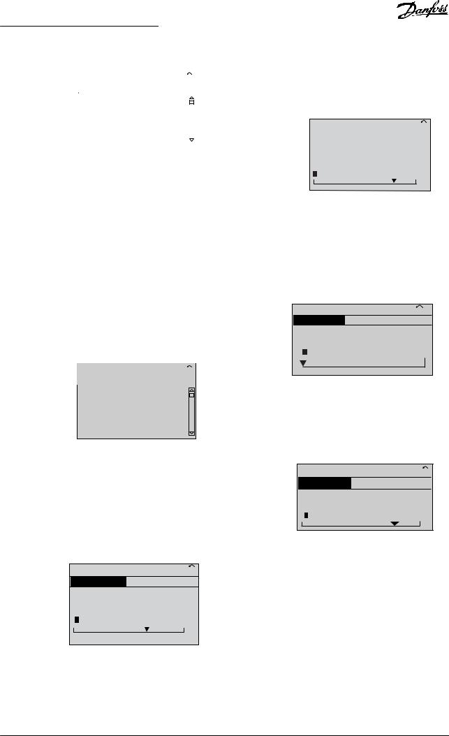
How to Program |
Programming Guide |
|
|
0 -01 Language |
|
|
|
130BP067.10 |
740RPM |
10.64A |
1 [1] |
|
|
Basic Settings |
|
0-0* |
|
|
[0] English |
|
|
|
|
|
|
|
|
|
|
|
|
|
|
Illustration 2.16 Parameter Selection
2.2.11 Changing Data
The procedure for changing data is the same in the quick menu mode and the main menu mode. Press [OK] to change the selected parameter.
The procedure for changing data depends on whether the selected parameter represents a numeric data value or a text value.
2.2.12 Changing a Text Value
Press [▲] [▼] keys to change the data value. [▲] increases |
|
|
|
|
|||||
the data value, and [▼] decreases the data value. Place the |
|
|
|
||||||
2 |
|
2 |
|||||||
cursor on the value to save and press [OK]. |
|
|
|
|
|||||
|
|
|
|
|
|
||||
|
1 - 60 Low speed load |
|
|
|
130BP070.10 |
|
|
|
|
|
|
|
|
|
|
|
|||
|
729RPM |
6.21A |
1(1) |
|
|
|
|
|
|
|
|
|
|
|
|
|
|
|
|
|
Load depen. setting |
|
|
1- 6* |
|
|
|
|
|
|
|
|
|
|
|
|
|
|
|
compensation
160%
Illustration 2.19 Saving a Data Value
2.2.14In€nitely Variable Change of Numeric Data Value
If the selected parameter shows a numeric data value, select a digit with [ ] [ ].
If the selected parameter is a text value, change the text value with the [▲] [▼] keys.
Place the cursor on the value to save and press [OK].
0 -01 Language |
10.64 A |
1 [1] |
130BP068.10 |
||
740RPM |
|
||||
Basic Settings |
|
|
0-0* |
|
|
[0] English
Illustration 2.17 Changing a Text Value
2.2.13 Changing a Data Value
If the selected parameter shows a numeric data value, change the selected data value with the [ ] [ ] navigation keys and the [▲] [▼] navigation keys. Press [ ] [ ] keys to move the cursor horizontally.
113 RPM |
1.78 A |
1(1) |
130BP069.10 |
Load depen. setting |
|
1- 6* |
|
1 - 60 Low speed load |
|
|
|
|
|
|
|
compensation |
|
|
|
100% |
|
|
|
Illustration 2.18 Changing a Data Value
635 RPM |
0.44 A |
1 (1) |
130BP073.10 |
Start Adjustments |
|
1- 7* |
|
1 - 71 Start Delay |
|
|
|
|
|
|
|
00.0s |
|
|
|
Illustration 2.20 Selecting a Digit
Change the selected digit in€nitely variably with [▲] [▼]. The cursor indicates the selected digit. Place the cursor on the digit to save and press [OK].
957RPM |
11.58A |
1 (1) |
130BP072.10 |
Start Adjustments |
|
1-7* |
|
1-71 High starting torque time |
|
|
|
|
|
|
|
0.4s |
|
|
|
Illustration 2.21 Saving
2.2.15 Value, Step-by-step
Certain parameters can be changed step by step. This applies to:
•Parameter 1-20 Motor Power [kW].
•Parameter 1-22 Motor Voltage.
•Parameter 1-23 Motor Frequency.
The parameters are changed both as a group of numeric data values and as numeric data values that are in€nitely varying.
MG20OA02 |
Danfoss A/S © 05/2016 All rights reserved. |
23 |
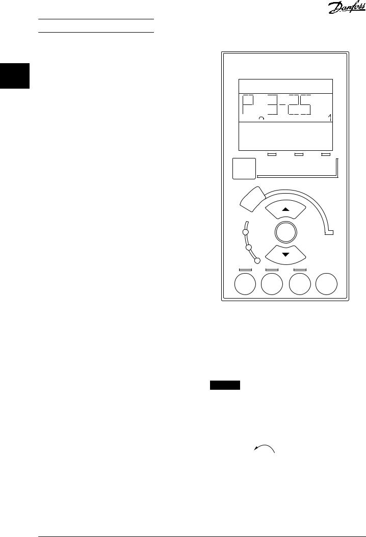
How to Program |
VLT® AQUA Drive FC 202 |
2.2.16Readout and Programming of Indexed Parameters
2 2 Parameters are indexed when placed in a rolling stack.
Parameter 15-30 Alarm Log: Error Code to
parameter 15-32 Alarm Log: Time contain a fault log, which can be read out. Select a parameter, press [OK], and press the keys [▲] [▼] to scroll through the value log.
For example, parameter 3-10 Preset Reference is changed as follows:
1.Select the parameter, press [OK], and press [▲] [▼] to scroll through the indexed values.
2.To change the parameter value, select the indexed value and press [OK].
3.Change the value by pressing [▲] [▼].
4.Press [OK] to accept the new setting.
5.Press [Cancel] to abort. Press [Back] to leave the parameter.
1 |
Setup |
|
|
Status |
Quick |
Main |
2 |
Menu |
Setup |
Menu |
|
|
||
|
Back |
|
|
130BA191.10
2.2.17How to Program on the Numerical Local Control Panel
The following instructions are valid for the numerical LCP (LCP 101).
The control panel is divided into 4 functional groups:
1.Numerical display.
2.Menu keys and indicator lights - changing parameters and switching between display functions.
3.Navigation keys and indicator lights.
4.Operation keys and indicator lights.
Display line
Status messages showing icons and numeric value.
Indicator lights
•Green LED/On: Indicates if control section is on.
•Yellow LED/Wrn: Indicates a warning.
•Flashing red LED/Alarm: Indicates an alarm.
LCP keys [Menu]
Select 1 of the following modes:
•Status.
•Quick set-up.
•Main menu.
3 On OK
Warn.
Alarm
4 |
Hand |
O |
Auto |
Reset |
|
on |
on |
||||
|
|
|
Illustration 2.22 LCP Keys
Status mode
Status mode shows the status of the frequency converter or the motor.
If an alarm occurs, the NLCP automatically switches to status mode.
Several alarms can be shown.
NOTICE
Parameter copy is not possible with LCP 101 numerical local control panel.
22.8 Setup 1 |
130BP077.10 |
|
rpm |
||
|
||
|
|
Illustration 2.23 Status Mode
24 |
Danfoss A/S © 05/2016 All rights reserved. |
MG20OA02 |
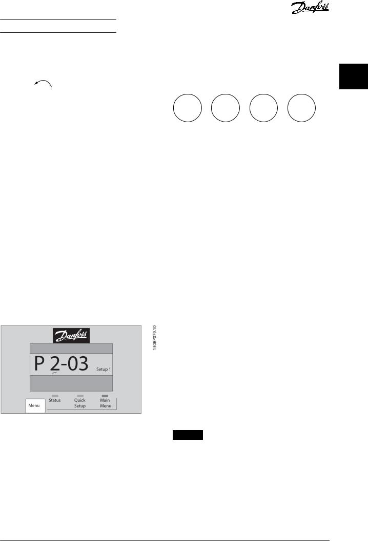
How to Program Programming Guide
|
|
|
2.2.18 LCP Keys |
|
|
|
|||
A 17 |
|
130BP078.10 |
|
|
|
||||
Setup 1 |
Keys for local control are at the bottom of the LCP. |
||||||||
|
|
||||||||
|
|
|
|||||||
|
|
|
|
|
|
|
|
|
|
Illustration 2.24 Alarm |
|
|
|
|
|
|
|
|
|
|
|
|
Hand |
|
O |
|
Auto |
Reset |
|
|
|
|
|
|
|
||||
|
|
|
|
on |
|
|
on |
||
|
|
|
|
|
|
|
|
||
2 2
130BP046.10
Main Menu/Quick Set-up
Are used for programming all parameters or only the parameters in the Quick Menu (see also description of the LCP 102 in chapter 2.1 The Graphical and Numerical Local Control Panel).
When the value flashes, press [▲] or [▼] to change parameter values.
1.Press [Main Menu] to select main menu.
2.Select the parameter group [xx-__] and press [OK].
3.Select the parameter [__-xx] and press [OK].
4.If the parameter is an array parameter, select the array number and press [OK].
5.Select the required data value and press [OK].
Parameters with functional options show values such as [1], [2], and so on. For a description of the different options, see the individual parameter descriptions in chapter 3 Parameter Description.
[Back]
Used for stepping backwards.
[▲] [▼] are used for maneuvering between commands and within parameters.
Illustration 2.25 Main Menu/Quick Set-up
Illustration 2.26 LCP Keys
[Hand On]
Enables control of the frequency converter via the LCP. [Hand On] also starts the motor and it is now possible to enter the motor speed data with the navigation keys. The key can be selected as [1] Enable or [0] Disable via parameter 0-40 [Hand on] Key on LCP.
External stop signals activated with control signals, or a €eldbus, override a start command via the LCP.
The following control signals are still active when [Hand On] is activated:
•[Hand On] - [Off] - [Auto On].
•Reset.
•Coast stop inverse.
•Reversing.
•Set-up select lsb - Set-up select msb.
•Stop command from serial communication.
•Quick stop.
•DC brake.
[Off]
Stops the connected motor. The key can be selected as [1] Enable or [0] Disable via parameter 0-41 [Off] Key on LCP.
If no external stop function is selected and the [Off] key is inactive, stop the motor by disconnecting the voltage.
[Auto On]
Enables control of the frequency converter via the control terminals and/or serial communication. When a start signal is applied on the control terminals and/or the bus, the frequency converter starts. The key can be selected as [1] Enable or [0] Disable via parameter 0-42 [Auto on] Key on LCP.
NOTICE
An active HAND-OFF-AUTO signal via the digital inputs has higher priority than the control keys [Hand On] and [Auto On].
[Reset]
Is used for resetting the frequency converter after an alarm (trip). It can be selected as [1] Enable or [0] Disable via parameter 0-43 [Reset] Key on LCP.
MG20OA02 |
Danfoss A/S © 05/2016 All rights reserved. |
25 |

How to Program VLT® AQUA Drive FC 202
2.3.1 Initialization to Default Settings Manual initialization
2 |
2 |
Initialize the frequency converter to default settings in 2 |
ways. |
Recommended initialization (via parameter 14-22 Operation Mode)
1.Select parameter 14-22 Operation Mode.
2.Press [OK].
3.Select [2] initialization.
4.Press [OK].
5.Disconnect the mains supply and wait until the display turns off.
6.Reconnect the mains supply. The frequency converter is now reset.
Parameter 14-22 Operation Mode initializes all except:
•Parameter 14-50 RFI Filter.
•Parameter 8-30 Protocol.
•Parameter 8-31 Address.
•Parameter 8-32 Baud Rate.
•Parameter 8-35 Minimum Response Delay.
•Parameter 8-36 Max Response Delay.
•Parameter 8-37 Maximum Inter-Char Delay.
•Parameter 15-00 Operating hours to parameter 15-05 Over Volt's.
•Parameter 15-20 Historic Log: Event to parameter 15-22 Historic Log: Time.
•Parameter 15-30 Alarm Log: Error Code to parameter 15-32 Alarm Log: Time.
1.Disconnect from mains and wait until the display turns off.
2.2a Press [Status] - [Main Menu] - [OK] at
the same time while powering up the LCP 102, graphical display.
2b Press [Menu] - [OK] while powering up the LCP 101, numerical display.
3.Release the keys after 5 s.
4.The frequency converter is now programmed according to default settings.
This procedure initializes all except:
•Parameter 15-00 Operating hours.
•Parameter 15-03 Power Up's.
•Parameter 15-04 Over Temp's.
•Parameter 15-05 Over Volt's.
NOTICE
A manual initialization also resets serial communication, RFI filter settings (parameter 14-50 RFI Filter), and fault log settings.
26 |
Danfoss A/S © 05/2016 All rights reserved. |
MG20OA02 |

Parameter Description |
Programming Guide |
|
|
3 Parameter Description
3.1 Parameter Selection
The parameters are grouped into various parameter groups for easy selection of the correct parameter for optimal operation |
|
3 |
3 |
|
|
|
|
||
of the frequency converter. |
|
|
|
|
Overview of parameter groups |
|
|
|
|
|
|
|
|
|
|
|
|
|
|
Group |
Function |
|
|
|
|
|
|
|
|
0-** Operation and Display |
Parameters related to the fundamental functions of the frequency converter, function of the LCP keys, |
|
|
|
|
and con€guration of the LCP display. |
|
|
|
|
|
|
|
|
1-** Load and Motor |
Parameters related to motor settings. |
|
|
|
|
|
|
|
|
2-** Brakes |
Parameters related to brake features in the frequency converter. |
|
|
|
|
|
|
|
|
3-** Reference/Ramps |
Parameters for handling of reference, de€nitions of limitations, and con€guration of the reaction of |
|
|
|
|
the frequency converter to changes. |
|
|
|
|
|
|
|
|
4-** Limits/Warnings |
Parameters for con€guring limits and warnings. |
|
|
|
|
|
|
|
|
5-** Digital In/Out |
Parameters for con€guring the digital inputs and outputs. |
|
|
|
|
|
|
|
|
6-** Analog In/Out |
Parameters for con€guring the analog inputs and outputs. |
|
|
|
|
|
|
|
|
8-** Communications and Options |
Parameter group for con€guring communications and options. |
|
|
|
|
|
|
|
|
9-** PROFIBUS |
Parameter group for Pro€bus-speci€c parameters (requires VLT® PROFIBUS DP MCA 101). |
|
|
|
10-** CAN Fieldbus |
Parameter group for DeviceNet-speci€c parameters (requires VLT® DeviceNet MCA 104). |
|
|
|
13-** Smart Logic |
Parameter group for smart logic control. |
|
|
|
|
|
|
|
|
14-** Special Functions |
Parameter group for con€guring special frequency converter functions. |
|
|
|
|
|
|
|
|
15-** Frequency Converter |
Parameter group containing frequency converter information such as operating data, hardware |
|
|
|
Information |
con€guration, and software versions. |
|
|
|
|
|
|
|
|
16-** Data Readouts |
Parameter group for data readouts, for example, actual references, voltages, control, alarm, warning, |
|
|
|
|
and status words. |
|
|
|
|
|
|
|
|
18-** Data Readouts 2 |
This parameter group contains the last 10 preventive maintenance logs. |
|
|
|
|
|
|
|
|
20-** FC Closed Loop |
This parameter group is used for con€guring the closed loop PID controller that controls the output |
|
|
|
|
frequency of the unit. |
|
|
|
|
|
|
|
|
21-** Extended Closed Loop |
Parameters for con€guring the 3 extended closed loop PID controllers. |
|
|
|
|
|
|
|
|
22-** Application Functions |
Parameters for water applications. |
|
|
|
|
|
|
|
|
23-** Time-based Functions |
Parameters for actions to be performed on a daily or weekly basis. |
|
|
|
|
|
|
|
|
24-** Application Functions 2 |
Parameters for the frequency converter bypass. |
|
|
|
|
|
|
|
|
25-** Cascade Controller |
Parameters for con€guring the basic cascade controller for sequence control of multiple pumps. |
|
|
|
|
|
|
|
|
26-** Analog I/O Option MCB 109 |
Parameters for con€guring the VLT® Analog I/O Option MCB 109. |
|
|
|
29-** Water Application Functions |
Parameters for setting water-speci€c functions. |
|
|
|
|
|
|
|
|
30-** Special Features |
Parameters for con€guring the special features. |
|
|
|
|
|
|
|
|
31-** Bypass Option |
Parameters for con€guring the bypass function. |
|
|
|
|
|
|
|
|
35-** Sensor Input Option |
Parameters for con€guring the sensor input function. |
|
|
|
|
|
|
|
|
Table 3.1 Parameter Groups
Parameter descriptions and selections are shown in the graphic LCP or the numeric LCP. See chapter 2 How to Program for details. Access the parameters by pressing
[Quick Menu] or [Main Menu] on the LCP. The Quick Menu is used primarily for commissioning the unit at start-up by providing the parameters necessary to start operation. The Main Menu provides access to all parameters for detailed application programming.
All digital input/output and analog input/output terminals are multifunctional. All terminals have factory default functions suitable for most water applications, but if other
special functions are required, they must be programmed in parameter groups 5-** Digital In/out or 6-** Analog In/ out.
MG20OA02 |
Danfoss A/S © 05/2016 All rights reserved. |
27 |
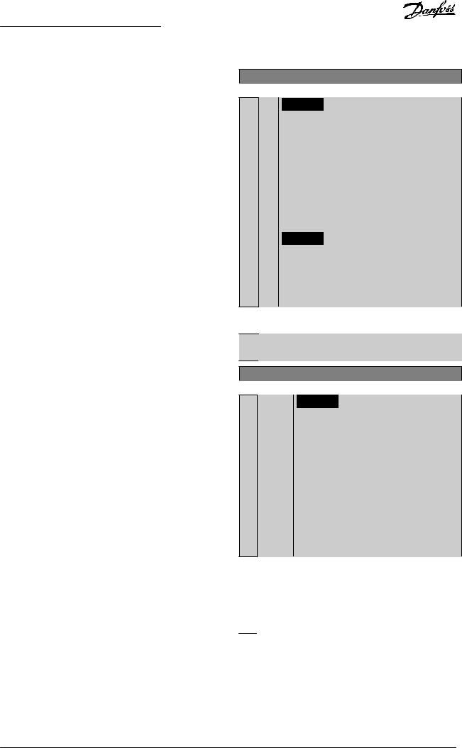
Parameter Description |
VLT® AQUA Drive FC 202 |
3.2 Parameters 0-** Operation and Display
Parameters related to the fundamental functions of the frequency converter, function of the LCP keys, and con€guration of the LCP display.
3 |
3 |
|
3.2.1 |
0-0* Basic Settings |
||
|
|
|
|
|
|
|
|
|
|
|
|
|
|
|
|
|
0-01 |
Language |
|
|
|
|
|
Option: |
Function: |
||
|
|
|
|
|
|
|
|
|
|
|
|
|
De€nes the language to be used in the |
|
|
|
|
|
|
display. |
|
|
|
|
|
|
The frequency converter is delivered with |
|
|
|
|
|
|
2 different language packages. English and |
|
|
|
|
|
|
German are included in both packages. |
|
|
|
|
|
|
English cannot be erased or manipulated. |
|
|
|
|
|
|
|
|
|
|
[0] * |
|
English |
Part of language packages 1–2. |
|
|
|
|
|
|
|
|
|
|
[1] |
|
Deutsch |
Part of language packages 1–2. |
|
|
|
|
|
|
|
|
|
|
[2] |
|
Francais |
Part of language package 1. |
|
|
|
|
|
|
|
|
|
|
[3] |
|
Dansk |
Part of language package 1. |
|
|
|
|
|
|
|
|
|
|
[4] |
|
Spanish |
Part of language package 1. |
|
|
|
|
|
|
|
|
|
|
[5] |
|
Italiano |
Part of language package 1. |
|
|
|
|
|
|
|
|
|
|
[6] |
|
Svenska |
Part of language package 1. |
|
|
|
|
|
|
|
|
|
|
[7] |
|
Nederlands |
Part of language package 1. |
|
|
|
|
|
|
|
|
|
|
[10] |
|
Chinese |
Part of language package 2. |
|
|
|
|
|
|
|
|
|
|
[20] |
|
Suomi |
Part of language package 1. |
|
|
|
|
|
|
|
|
|
|
[22] |
|
English US |
Part of language package 1. |
|
|
|
|
|
|
|
|
|
|
[27] |
|
Greek |
Part of language package 1. |
|
|
|
|
|
|
|
|
|
|
[28] |
|
Bras.port |
Part of language package 1. |
|
|
|
|
|
|
|
|
|
|
[36] |
|
Slovenian |
Part of language package 1. |
|
|
|
|
|
|
|
|
|
|
[39] |
|
Korean |
Part of language package 2. |
|
|
|
|
|
|
|
|
|
|
[40] |
|
Japanese |
Part of language package 2. |
|
|
|
|
|
|
|
|
|
|
[41] |
|
Turkish |
Part of language package 1. |
|
|
|
|
|
|
|
|
|
|
[42] |
|
Trad.Chinese |
Part of language package 2. |
|
|
|
|
|
|
|
|
|
|
[43] |
|
Bulgarian |
Part of language package 1. |
|
|
|
|
|
|
|
|
|
|
[44] |
|
Srpski |
Part of language package 1. |
|
|
|
|
|
|
|
|
|
|
[45] |
|
Romanian |
Part of language package 1. |
|
|
|
|
|
|
|
|
|
|
[46] |
|
Magyar |
Part of language package 1. |
|
|
|
|
|
|
|
|
|
|
[47] |
|
Czech |
Part of language package 1. |
|
|
|
|
|
|
|
|
|
|
[48] |
|
Polski |
Part of language package 1. |
|
|
|
|
|
|
|
|
|
|
[49] |
|
Russian |
Part of language package 1. |
|
|
|
|
|
|
|
|
|
|
[50] |
|
Thai |
Part of language package 2. |
|
|
|
|
|
|
|
|
|
|
[51] |
|
Bahasa |
Part of language package 2. |
|
|
|
|
|
Indonesia |
|
|
|
|
|
|
|
|
|
|
|
[52] |
|
Hrvatski |
Part of language package 2. |
|
|
|
|
|
|
|
0-02 Motor Speed Unit
Option: Function:
NOTICE
This parameter cannot be adjusted while the motor is running.
The information shown in the display depends on settings in parameter 0-02 Motor Speed Unit and parameter 0-03 Regional Settings. The default settings of parameter 0-02 Motor Speed Unit and
parameter 0-03 Regional Settings depend on to which region of the world the frequency converter is supplied.
NOTICE
Changing the motor speed unit resets certain parameters to their initial value. Select the motor speed unit before modifying other parameters.
[0] * RPM Select to show motor speed variables and parameters using motor speed (RPM).
[1] Hz Select to show motor speed variables and parameters using output frequency (Hz).
0-03 Regional Settings
Option: Function:
NOTICE
This parameter cannot be adjusted while the motor is running.
The display output depends on the settings in parameter 0-02 Motor Speed Unit and parameter 0-03 Regional Settings. The default
settings of parameter 0-02 Motor Speed Unit and parameter 0-03 Regional Settings depend on which region of the world the frequency converter is supplied to. Reprogram the settings as required.
The settings not used are made invisible.
[0]InternaSets parameter 1-20 Motor Power [kW] units to
* |
tional |
[kW] and the default value of |
|
|
|
parameter 1-23 |
Motor Frequency [50 Hz]. |
|
|
|
|
[1] |
North |
Sets parameter 1-21 Motor Power [HP] units to |
|
|
America |
[hp] and the default value of |
|
|
|
parameter 1-23 |
Motor Frequency to 60 Hz. |
|
|
|
|
28 |
Danfoss A/S © 05/2016 All rights reserved. |
MG20OA02 |
 Loading...