


 Loading...
SmartBase PC1200s/ iR1200s
REVISION 0
DEC. 2001 |
HY8-10AU-000 |
COPYRIGHT © 2001 CANON INC. |
CANON SmartBase PC1200s/iR1200s REV. 0 DEC. 2001 |
Application
This manual has been issued by Canon Inc. for qualified persons to learn technical theory, installation, maintenance, and repair of products. This manual covers all localities where the products are sold. For this reason, there may be information in this manual that does not apply to your locality.
Corrections
This manual may contain technical inaccuracies or typographical errors due to improvements or changes in products. When changes occur in applicable products or in the contents of this manual, Canon will release technical information as the need arises. In the event of major changes in the contents of this manual over a long or short period, Canon will issue a new edition of this manual.
The following paragraph does not apply to any countries where such provisions are inconsistent with local law.
Trademarks
The product names and company names used in this manual are the registered trademarks of the individual companies.
Copyright
This manual is copyrighted with all rights reserved. Under the copyright laws, this manual may not be copied, reproduced or translated into another language, in whole or in part, without the written consent of Canon Inc.
COPYRIGHT © 2001 CANON INC.
Caution
Use of this manual should be strictly supervised to avoid disclosure of confidential information.
COPYRIGHT © 2001 CANON INC. |
CANON SmartBase PC1200s/iR1200s REV. 0 DEC. 2001 |
INTRODUCTION
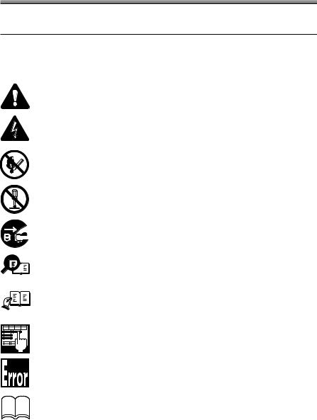
1 Symbols Used
This documentation uses the following symbols to indicate special information:
Symbol |
Description |
Memo
REF.
Indicates an item of a non-specific nature, possibly classified as Note, Caution, or Warning.
Indicates an item requiring care to avoid electric shocks.
Indicates an item requiring care to avoid combustion (fire).
Indicates an item prohibiting disassembly to avoid electric shocks or problems.
Indicates an item requiring disconnection of the power plug from the electric outlet.
Indicates an item intended to provide notes assisting the understanding of the topic in question.
Indicates an item of reference assisting the understanding of the topic in question.
Provides a description of a service mode.
Provides a description of the nature of an error indication.
Refers to the Copier Basics Series for a better understanding of the contents.
COPYRIGHT © 2001 CANON INC. |
CANON SmartBase PC1200s/iR1200s REV. 0 DEC. 2001 |
i |

INTRODUCTION
2 Outline of the Manual
This Service Manual provides basic facts and figures needed to service the SmartBase PC1200 Series/iR1200 Series products in the field, and it consists of the following chapters:
Chapter 1 |
Product Outline: |
specifications, names of parts, safety and warnings |
Chapter 2 Using the Machine: |
control panel, user mode, service mode |
|
Chapter 3 |
Installation: |
site requirements, installation procedure, work for reloca- |
|
|
tion |
Chapter 4 |
Operation: |
mechanical system by function, principles of operation of |
|
|
electrical systems |
Chapter 5 |
Mechanical System: |
mechanical construction, disassembly/assembly |
Chapter 6 |
Maintenance and Inspection: periodically replaced parts, durables (life), basic servicing |
|
|
|
chart, cleaning |
Chapter 7 |
Troubleshooting: |
standards/adjustments, troubleshooting image faults, |
|
|
troubleshooting malfunctions |
Appendix: |
|
general timing chart, general circuit diagrams |
ii |
COPYRIGHT © 2001 CANON INC. |
CANON SmartBase PC1200s/iR1200s REV. 0 DEC. 2001 |

INTRODUCTION
The descriptions in this Service Manual are based on he following rules:
1.In each chapter, the uses of the function in question and its relationship to electrical and mechanical systems are discussed and the timing of operation of its associated parts is explained by means of outlines and diagrams.
In the diagrams, the symbol  represents a mechanical path, while the symbol
 with a name next to it indicates the flow of an electric signal.
The expression “turn on the power” means turning on the power switch, closing the front cover, and closing the delivery cover so that the machine will be supplied with power.
2.In circuit diagrams (digital), a signal whose level is High is expressed as being ‘1’, while a single whose level is Low is expressed as being ‘0’; the level of voltage, however, varies from circuit to circuit.
The machine uses CPUs, whose internal mechanisms cannot be checked in the field, and, therefore, are not explained. In addition, the machine’s PCBs are not intended for repairs at the user’s and, therefore, are explained by means of block diagrams: two types are used, i.e., between sensors and inputs of PCBs equipped with a control or drive function and between outputs equipped with a control or drive function and loads; in addition, functional block diagrams are used at times.
Changes made to the machine for product improvement are communicated in the form of a Service Information bulletin as needed. All service persons are expected to go through all service documentation including the bulletins and be equipped to respond to the needs of the field (as by being able to identify possible causes of problems).
COPYRIGHT © 2001 CANON INC. |
CANON SmartBase PC1200s/iR1200s REV. 0 DEC. 2001 |
iii |

INTRODUCTION
This service manual covers the models shown in the following table. Be sure to have a good understanding of the difference from model to model before referring to this manual.
Model |
Type |
ADF |
Printer |
Fax |
Counter |
Default |
Cassette |
Copying speed |
|
code |
function |
function |
function |
function |
ratio |
|
(cpm) at Direct |
|
|
|
|
|
|
|
|
|
iR1210G |
UJA |
|
√ |
|
√ |
2R2E |
250 sheets |
12cpm/A4 |
iR1230G |
UKA |
√ |
√ |
|
√ |
2R2E |
250 sheets |
12cpm/A4 |
PC1210D |
UGA/ |
|
√ |
|
|
2R2E |
250 sheets |
12cpm/A4 |
|
UUK |
|
|
|
|
|
|
|
PC1230D |
UHA/ |
√ |
√ |
|
|
2R2E |
250 sheets |
12cpm/A4 |
|
UUM |
|
|
|
|
|
|
|
|
|
|
|
|
|
|
|
|
PC1270D |
UIA |
√ |
√ |
√ |
|
2R2E |
250 sheets |
12cpm/A4 |
The notation “√ ” indicates that the item in question is available.
iv |
COPYRIGHT © 2001 CANON INC. |
CANON SmartBase PC1200s/iR1200s REV. 0 DEC. 2001 |

CONTENTS
Contents
CHAPTER 1 PRODUCT OUTLINE
1 Specifications ...................................... |
1-1 |
|
1.1 |
Type ............................................ |
1-1 |
1.2 |
Mechanisms ............................... |
1-1 |
1.3 |
Functions .................................... |
1-2 |
1.4 |
Others ......................................... |
1-3 |
1.5 |
Copying Speed ........................... |
1-4 |
1.6 |
ADF (if equipped with ADF |
|
|
functions) ................................... |
1-5 |
1.7FAX (if equipped fax functions) 1-6
1.7.1Communications
specifications ....................... |
1-6 |
1.7.2Scanner section
specifications ....................... |
1-7 |
1.7.3Printer section
|
specifications ....................... |
1-7 |
1.7.4 |
Functions ............................. |
1-8 |
2 Names of Parts .................................. |
1-12 |
|
2.1 External View ........................... |
1-12 |
|
2.1.1 |
Body (ADF type) ............... |
1-12 |
2.1.2 |
Body (copyboard type) ...... |
1-13 |
2.1.3ADF (if equipped with ADF
functions) ........................... |
1-15 |
2.2 Cross Section ........................... |
1-16 |
2.2.1 Body .................................. |
1-16 |
2.2.2ADF (if equipped with ADF
|
functions) ........................... |
1-17 |
3 Safety and Warnings ......................... |
1-18 |
|
3.1 |
Safety of Laser Light ......... |
1-18 |
3.1.1 Safety of the Laser Unit ..... |
1-18 |
|
3.1.2 CDRH Requirements ......... |
1-18 |
|
3.1.3 Handling the Laser Unit .... |
1-19 |
|
3.2 |
Safety of the Toner ................... |
1-20 |
3.3 |
Storing and Handling the |
|
|
Cartridge .................................. |
1-20 |
3.3.1Storing a Cartridge Before
Unpacking .......................... |
1-20 |
3.3.2Storing or Handling the Cartridge After Unpacking 1-21
3.3.2.1Storing After Unpacking1-21
3.3.2.2Points to Note When Handling the Cartridge . 1-22
CHAPTER 2 USING THE MACHINE
1 Using the Machine .............................. |
2-1 |
3 Service Mode .................................... |
2-20 |
|||
1.1 |
Control Panel ............................. |
2-1 |
3.1 |
Outline ..................................... |
2-20 |
|
2 User Mode .......................................... |
2-5 |
3.2 |
Using Service Mode ................ |
2-22 |
||
2.1 |
User Mode Menu ....................... |
2-5 |
3.3 |
List of Service Mode Menus ... |
2-23 |
|
2.2 |
User Report .............................. |
2-17 |
3.4 |
Bit Switch Settings |
|
|
2.2.1 |
Manually Generating a |
|
|
(#1 SSSW) ............................... |
2-31 |
|
|
|
Report ................................ |
2-17 |
3.5 |
Menu Switch Settings |
|
2.2.2 |
Automatically Generating |
|
|
(#2 MENU) .............................. |
2-44 |
|
|
|
Reports (if equipped with fax |
3.6 |
Numeric Parameter Setting |
|
|
|
|
functions) ........................... |
2-18 |
|
(#3 NUMERIC Param.) ........... |
2-46 |
2.2.2.1 Memory Clear List ....... |
2-19 |
3.7 |
SPECIAL Setting |
|
||
|
|
|
|
|
(#4A SPECIAL) ....................... |
2-49 |
|
|
|
|
3.8 |
NCU Setting (#4B NCU) ......... |
2-49 |
COPYRIGHT © 2001 CANON INC. |
CANON SmartBase PC1200s/iR1200s REV. 0 DEC. 2001 |
v |

CONTENTS
3.9 ISDN Setting (#4C ISDN) ....... |
2-49 |
3.21.6 |
MODEM NCU Test |
|
||
3.10 |
Country/Region of Installation |
|
|
(4: MODEM NCU) ........... |
2-77 |
|
|
(#5 TYPE) ................................ |
2-49 |
3.21.6.1 Relay Test ..................... |
2-77 |
||
3.11 |
Setting the Original Reading |
|
3.21.6.2 Frequency Test .............. |
2-78 |
||
|
Functions (#6 SCANNER) ...... |
2-50 |
3.21.6.3 G3 Signal Transmission |
|
||
3.12 |
Setting the Printer Parameters |
|
|
Test ................................ |
2-78 |
|
|
(#7 PRINTER) ......................... |
2-51 |
3.21.6.4 DTMF Signal Transmission |
|||
3.12.1 |
#1 SSSW Setting ............... |
2-51 |
|
Test ................................ |
2-79 |
|
3.12.2 |
#2 NUMERIC Param. |
|
3.21.6.5 Tonal/DTMF Signal |
|
||
|
|
Setting ................................ |
2-52 |
|
Reception Test .............. |
2-79 |
3.12.3 |
#3 PRINT COUNT ............ |
2-52 |
3.21.7 |
AGING Test |
|
|
3.12.4 |
#4 PRINT RESET ............. |
2-52 |
|
(5: AGING TEST) ............. |
2-80 |
|
3.12.5 |
#5 MLT CLEANING ......... |
2-52 |
3.21.8 |
FACULTY (function) Test |
|
|
3.13 |
PDL (#8 PDL) .......................... |
2-52 |
|
(6: FACULTY TEST) ........ |
2-80 |
|
3.14 |
Counter (#9 COUNTER) ......... |
2-53 |
3.21.9 |
BOOK Read Test |
|
|
3.14.1 |
Counter .............................. |
2-53 |
|
(8: BOOK TEST) .............. |
2-86 |
|
3.14.2 |
Clearing the Counter |
|
3.22 Service Report .......................... |
2-87 |
||
|
|
Readings ............................ |
2-54 |
3.22.1 |
Manually Generating |
|
3.15 |
Generating a Report |
|
|
Reports ............................... |
2-87 |
|
|
(#10 REPORT) ......................... |
2-54 |
3.22.1.1 SYSTEM (SERVICE) |
|
||
3.16 |
Downloading |
|
|
DATA LIST ................... |
2-87 |
|
|
(#11 DOWNLOAD) ................ |
2-54 |
3.22.1.2 SYSTEM DUMP |
|
||
3.17 |
Clearing (#12 CLEAR) ............ |
2-55 |
|
LIST .............................. |
2-88 |
|
3.18 |
ROM Indication (#13 ROM) ... |
2-55 |
3.22.1.3 KEY HISTORY |
|
||
3.19 |
Resetting the Contact Sensor Posi- |
|
REPORT ....................... |
2-90 |
||
|
tion (#14 CS SET) ................... |
2-55 |
3.22.1.4 COUNTER REPORT ... |
2-91 |
||
3.20 |
Service Mode Default Setting .. |
2-56 |
3.22.1.5 PRINT SPEC |
|
||
3.21 |
Test Mode (TEST MODE) ...... |
2-66 |
|
REPORT ....................... |
2-92 |
|
3.21.1 |
Outline ............................... |
2-66 |
3.22.2 |
Automatically Generated |
|
|
3.21.2 List of Test Mode Items ..... |
2-67 |
|
Reports ............................... |
2-92 |
||
3.21.3 D-RAM Test (1: DRAM) .. |
2-74 |
3.22.2.1 Error TX Report |
|
|||
3.21.4 CCD Test (2: CCD TEST) . 2-75 |
|
(for service) .................. |
2-93 |
|||
3.21.5 PRINT Test (3: PRINT) ..... |
2-76 |
3.22.2.2 RX Report (for service) 2-94 |
||||
CHAPTER 3 INSTALLATION
1 |
Selecting the Site ................................ |
3-1 |
2.5 |
Putting Paper in the Cassette ..... |
3-7 |
|
2 |
Unpacking and Installing the |
|
2.6 |
Putting Paper in the Manual |
|
|
|
Machine .............................................. |
3-2 |
|
Feed Tray ................................... |
3-8 |
|
|
2.1 |
Before Starting ........................... |
3-2 |
2.7 |
Connecting the Interface Cable .. |
3-9 |
|
2.2 |
Installation Procedure ................ |
3-2 |
2.8 |
Connecting the Modular Cable |
|
|
2.3 |
Unpacking .................................. |
3-3 |
|
(if equipped with fax functions) |
3-9 |
|
2.4 |
Fitting the Cartridge ................... |
3-5 |
2.9 |
Connecting the Power Cord ..... |
3-10 |
vi |
COPYRIGHT © 2001 CANON INC. |
CANON SmartBase PC1200s/iR1200s REV. 0 DEC. 2001 |

CONTENTS
2.10 |
Fitting the Delivery Tray .......... |
3-10 |
2.11 |
Checking the Copy Images ...... |
3-10 |
2.12 |
Setting the Printer Functions ... |
3-11 |
2.13 |
Setting Fax Functions (if equipped |
|
|
with fax functions) ................... |
3-12 |
CHAPTER 4 OPERATION
1 Basic Operation .................................. |
4-1 |
|||
1.1 |
Reproduction Processes ............. |
4-1 |
||
1.1.1 |
Outline ................................. |
4-1 |
||
1.2 |
Functional Construction ............ |
4-4 |
||
1.3 Outline of the Electrical |
|
|||
|
Circuitry ..................................... |
4-5 |
||
1.3.1 |
Functional Block Diagram .. |
4-5 |
||
1.3.2 |
Outlines of Functions .......... |
4-6 |
||
1.3.2.1 |
Image Processor PCB ..... |
4-6 |
||
1.3.2.2 |
DC Controller PCB ........ |
4-7 |
||
1.3.2.3 |
Control Panel PCB ......... |
4-8 |
||
1.3.2.4 |
Power Supply PCB ......... |
4-8 |
||
1.3.2.5 |
Analog Processor PCB ... |
4-9 |
||
1.3.2.6 |
Sensor PCB ..................... |
4-9 |
||
1.3.2.7 |
Laser Driver/BD PCB ..... |
4-9 |
||
1.3.2.8Main Motor/Scanner Motor
|
Driver .............................. |
4-9 |
1.3.2.9 |
Printer Controller PCB ... |
4-9 |
1.3.2.10 |
NCU PCB (if equipped with |
|
|
fax functions) ................ |
4-10 |
1.3.2.11Modular Jack PCB (if equipped with fax
|
|
functions) ...................... |
4-10 |
|
1.4 |
Power-On Sequence ................. |
4-11 |
|
1.5 |
Controlling the Main Motor .... |
4-12 |
|
1.5.1 Outline ............................... |
4-12 |
|
2 |
Image Reading/Processing System ... |
4-13 |
|
|
2.1 |
Outline ..................................... |
4-13 |
3 |
Laser Exposure System .................... |
4-14 |
|
|
3.1 |
Outline ..................................... |
4-14 |
4 |
Image Formation System .................. |
4-16 |
|
|
4.1 |
Outline ..................................... |
4-16 |
5 |
Pickup/Feeding/Delivery System ..... |
4-17 |
|
|
5.1 |
Outline ..................................... |
4-17 |
2.13.1 Setting the Date/Time (user |
|
|
|
mode) ................................. |
3-12 |
2.13.2 |
Setting the Dial Type ......... |
3-13 |
2.13.3 |
Executing Communications |
|
|
Testing ............................... |
3-13 |
3 When Relocating the Machine ......... |
3-14 |
|
5.2 Pickup Operation ..................... |
4-18 |
|
5.2.1 Pickup from the Cassette ... |
4-18 |
|
5.2.1.1 |
Outline .......................... |
4-18 |
5.2.1.2 |
Retry Pickup ................. |
4-19 |
5.2.1.3 Detecting the Size of |
|
|
|
Paper ............................. |
4-19 |
5.2.2Pickup from the Manual
|
|
Feed Tray ........................... |
4-20 |
|
|
5.2.2.1 |
Outline .......................... |
4-20 |
|
|
5.2.2.2 |
Retry Pickup ................. |
4-21 |
|
|
5.2.2.3 Detecting the Size of |
|
||
|
|
|
Paper ............................. |
4-21 |
5.3 |
Feeding Operation/Delivery |
|
||
|
Operation ................................. |
4-22 |
||
5.3.1 |
Outline ............................... |
4-22 |
||
5.3.2 |
Auto Delivery Control ....... |
4-22 |
||
5.4 |
Reducing the Copying Speed .. |
4-23 |
||
5.4.1 |
Outline ............................... |
4-23 |
||
5.5 |
Detecting Jams ......................... |
4-24 |
||
5.5.1 |
Outline ............................... |
4-24 |
||
5.5.2 |
Types of Jams .................... |
4-24 |
||
6 Fixing System ................................... |
4-26 |
|||
6.1 |
Outline ..................................... |
4-26 |
||
6.2 |
Controlling the Fixing |
|
||
|
Operation ................................. |
4-27 |
||
6.2.1Controlling the Fixing
Temperature ....................... |
4-27 |
6.2.2Controlling the Fixing Film
Bias .................................... |
4-29 |
6.2.3Fixing Heater Safety
Mechanism......................... |
4-29 |
6.2.4Detecting a Fault in the
Fixing Assembly ................ |
4-29 |
COPYRIGHT © 2001 CANON INC. |
CANON SmartBase PC1200s/iR1200s REV. 0 DEC. 2001 |
vii |

CONTENTS
7 Power Supply System ....................... |
4-31 |
8.2.1.3 |
Vanadium Lithium |
|
||
7.1 |
Low Voltage Circuit ................. |
4-31 |
|
Secondary Battery |
|
|
7.1.1 |
Low Voltage Power Supply |
|
|
(BAT2) .......................... |
4-37 |
|
|
|
Circuit ................................ |
4-31 |
8.2.2 Back-Up Data .................... |
4-38 |
|
7.1.2 |
Protective Functions .......... |
4-33 |
8.2.2.1 |
Types of Data ................ |
4-38 |
|
7.2 |
High-Voltage Power Supply |
|
8.2.2.2 Printing the Backup Data |
|||
|
Circuit ...................................... |
4-33 |
|
List ................................ |
4-40 |
|
7.3 |
Controlling the ESS |
|
9 ADF (if equipped with ADF |
|
||
|
Mechanism ............................... |
4-33 |
functions) |
.......................................... |
4-41 |
|
7.3.1 |
Outline ............................... |
4-33 |
9.1 |
Outline ..................................... |
4-41 |
|||
7.3.2 |
Operation ........................... |
4-33 |
9.2 |
Picking Up and Moving |
|
|||
8 Others ................................................ |
|
|
4-34 |
|
Originals ................................... |
4-42 |
||
8.1 |
Fan |
|
........................................... |
4-34 |
9.2.1 |
Outline ............................... |
4-42 |
|
8.1.1 |
Outline ............................... |
4-34 |
9.2.2 Moving Down the Original |
|
||||
8.2 |
Back ....................-Up Batteries |
4-35 |
|
|
Pickup Roller and Moving Up |
|||
8.2.1 |
Back .............-Up Function |
4-35 |
|
|
the Original Stopper .......... |
4-43 |
||
|
8.2.1.1 .......................... |
Outline |
4-35 |
9.3 |
Detecting an Original Jam ....... |
4-44 |
||
|
8.2.1.2 |
Lithium Battery |
|
9.3.1 |
Outline ............................... |
4-44 |
||
|
|
.......................... |
(BAT1) |
4-35 |
9.3.2 |
Types of Jams .................... |
4-44 |
|
CHAPTER 5 MECHANICAL SYSTEM
1 Points to Note When Disassembling/As-
sembling the Machine ......................... |
5-1 |
|
2 Disassembly ........................................ |
5-3 |
|
2.1 Externals/Auxiliary System ....... |
5-3 |
|
2.1.1 External Covers ................... |
5-3 |
|
2.1.1.1 Removing the Left Cover/Rear |
||
Cover ................................... |
5-4 |
|
2.1.1.2 |
Removing the Right |
|
|
Cover .............................. |
5-4 |
2.1.1.3 |
Removing the Front |
|
|
Cover .............................. |
5-5 |
2.1.1.4 |
Removing the Delivery |
|
|
Cover .............................. |
5-5 |
2.1.1.5Removing the Delivery Upper Cover/Delivery Rear
|
Cover .............................. |
5-6 |
2.1.1.6 |
Removing the Cartridge |
|
|
Cover .............................. |
5-6 |
2.1.1.7 Removing the Upper Cover |
||
|
........................................ |
5-7 |
2.1.1.8 |
Removing the Right |
|
|
Door ................................ |
5-8 |
2.1.2Removing the Control
Panel .................................... |
5-8 |
2.1.3Removing the Copyboard
Glass .................................. |
5-10 |
2.1.4Removing the Main Motor
Unit .................................... |
5-10 |
2.1.5 Remove the Fan ................. |
5-14 |
2.1.6Removing the Reader Unit
|
Slide Detecting Switch ...... |
5-16 |
2.2 PCBs ........................................ |
5-17 |
|
2.2.1 |
Removing the Image |
|
|
Processor PCB ................... |
5-17 |
2.2.2 |
Removing the Analog |
|
|
Processor PCB ................... |
5-17 |
2.2.3Removing the Sensor
PCB .................................... |
5-20 |
2.2.4Removing the DC Controller
PCB/Power Supply PCB ... 5-21
2.2.5Removing the Printer
Controller PCB .................. |
5-25 |
viii |
COPYRIGHT © 2001 CANON INC. |
CANON SmartBase PC1200s/iR1200s REV. 0 DEC. 2001 |
CONTENTS
2.2.6Removing the NCU PCB (if equipped with fax
functions) ........................... |
5-25 |
2.2.7Removing the Modular Jack
PCB .................................... |
5-26 |
2.3 Original Reading/Processing |
|
System ...................................... |
5-27 |
2.3.1 Removing the Contact |
|
Sensor ................................ |
5-27 |
2.3.2Removing the Reader Motor
Drive Unit .......................... |
5-28 |
2.3.3Removing the Reader
Unit .................................... |
5-30 |
2.4 Laser Exposure System ............ |
5-32 |
2.4.1Removing the Laser Scanner
|
Unit .................................... |
5-32 |
2.5 |
Image Formation System ......... |
5-34 |
2.5.1 Removing the Transfer Charging |
||
|
Roller ....................................... |
5-34 |
2.6 |
Pickup/Feeding System ........... |
5-35 |
2.6.1Removing the Cassette Pickup
Roller ................................. |
5-35 |
2.6.2Removing the Cassette Pickup
Solenoid ............................. |
5-37 |
2.6.3Removing the Manual Feed
Tray (upper) ....................... |
5-39 |
2.6.4Removing the Manual Feed
Tray (lower) ....................... |
5-39 |
2.6.5Removing the Manual Feed
Pickup Roller ..................... |
5-40 |
2.6.6Removing the Separation
Pad ..................................... |
5-41 |
2.6.7Removing the Manual Feed Pickup Solenoid/Manual Feed
Tray Paper Sensor .............. |
5-41 |
2.6.8Removing the Vertical Path
Roller ................................. |
5-42 |
2.6.9Removing the Registration
Roller Unit ......................... |
5-42 |
2.7 Fixing System .......................... |
5-44 |
2.7.1Removing the Fixing
Assembly ........................... |
5-44 |
2.7.2Removing the Fixing Film Unit/
Fixing Pressure Roller ....... |
5-46 |
2.7.3 Removing the Delivery |
|
Sensor ................................ |
5-47 |
2.8 ADF System (if equipped with |
|
ADF functions) ........................ |
5-48 |
2.8.1Externals/Auxiliary Control
System ............................... |
5-48 |
|
2.8.1.1 |
Removing the ADF ....... |
5-48 |
2.8.1.2 Removing the ADF Drive |
||
|
Unit ............................... |
5-50 |
2.8.1.3 Removing the ADF Motor |
||
|
Unit ............................... |
5-51 |
2.8.1.4 Removing the Slide Guide |
||
|
(front, rear) ................... |
5-52 |
2.8.1.5 Mounting the Slide Guide |
||
|
(front, rear) ................... |
5-53 |
2.8.2 Pickup System ................... |
5-54 |
|
2.8.2.1 |
Removing the Separation |
|
|
Roller Unit .................... |
5-54 |
2.8.2.2Removing the Original Pickup roller/Original Sepa-
ration roller ................... |
5-56 |
2.8.2.3Removing the Original Sensor/Registration
|
Sensor ........................... |
5-56 |
2.8.2.4 |
Removing the Separation |
|
|
Pad ................................ |
5-57 |
2.8.2.5 Removing the ADF Registra- |
||
|
tion Roller ..................... |
5-58 |
2.8.3 Feeding System ................. |
5-60 |
|
2.8.3.1 |
Removing the White |
|
|
Roller ............................ |
5-60 |
2.8.3.2 Removing the Feeding Out- |
||
|
side Guide ..................... |
5-61 |
2.8.3.3 |
Removing the Feed |
|
|
Roll ............................... |
5-62 |
2.8.3.4 Removing the Original Feed |
||
|
Roller ............................ |
5-63 |
2.8.4 |
Delivery System ........... |
5-64 |
2.8.4.1Removing the Delivery Stacking Tray/Original
Delivery Roller ............. |
5-64 |
2.8.4.2 Removing the Original |
|
Delivery Sensor ............ |
5-65 |
COPYRIGHT © 2001 CANON INC. |
CANON SmartBase PC1200s/iR1200s REV. 0 DEC. 2001 |
ix |

CONTENTS
CHAPTER 6 MAINTENANCE AND INSPECTION
1 Periodically Replaced Parts ................ |
6-1 |
4.3.6 |
Transfer Guide ..................... |
6-5 |
|
2 Durables |
.............................................. |
6-1 |
4.3.7 |
Transfer Charging Roller ..... |
6-5 |
3 Scheduled Servicing Chart ................. |
6-1 |
4.3.8 |
Separation Static |
|
|
4 Cleaning |
.............................................. |
6-2 |
|
Eliminator ............................ |
6-5 |
4.1 Cleaning by the User |
|
4.3.9 |
Paper Path ............................ |
6-5 |
|
(machine) ................................... |
6-2 |
4.3.10 |
Fixing Inlet Guide ............... |
6-5 |
|
4.1.1 Cleaning the Fixing Pressure |
|
4.3.11 |
Fixing Pressure Roller ......... |
6-5 |
|
|
Roller ................................... |
6-2 |
4.3.12 |
Delivery Roller .................... |
6-6 |
4.1.2 |
Other Cleaning ..................... |
6-2 |
4.3.13 |
Back of Copyboard Glass |
|
4.2 Cleaning by the User (ADF) ...... |
6-3 |
|
(Back of Shading Plate) ....... |
6-6 |
|
4.2.1 |
Cleaning the White Roller ... |
6-3 |
4.4 Cleaning at Time of a Service |
|
|
4.2.2 |
Other Cleaning ..................... |
6-3 |
Visit (ADF) ................................ |
6-7 |
|
4.3 Cleaning at Time of a Service Visit |
4.4.1 |
Original Pickup Roller ......... |
6-7 |
||
(machine) ................................... |
6-4 |
4.4.2 |
Original Separation Roller ... |
6-7 |
|
4.3.1 Selfoc Lens Array of the |
|
4.4.3 |
Original Separation Pad ....... |
6-7 |
|
|
Contact Sensor ..................... |
6-4 |
4.4.4 |
ADF Registration Roller ...... |
6-7 |
4.3.2 |
Cassette Pickup Roller ......... |
6-5 |
4.4.5 |
Original Feed Roller ............ |
6-7 |
4.3.3 |
Manual Feed Pickup |
|
4.4.6 |
Original Delivery Roller ...... |
6-7 |
|
Roller ................................... |
6-5 |
4.4.7 |
Copyboard Glass |
|
4.3.4 |
Separation Pad ..................... |
6-5 |
|
(Original Reading Area) ...... |
6-8 |
4.3.5 |
Registration Roller ............... |
6-5 |
|
|
|
CHAPTER 7 TROUBLESHOOTING
1 Standards and Adjustments ................. |
7-1 |
1.1Checking Against the Standards 7-1
1.1.1Checking the Pressure (nip) of
the Fixing Pressure Roller ... |
7-1 |
1.2 Making Adjustments .................. |
7-3 |
1.2.1Making Adjustments When Re-
placing Major Parts .............. |
7-3 |
1.2.2Preparing a Test Sheet for Ad-
justment ............................... |
7-4 |
1.2.3Adjusting the Mechanical Sys-
tems ...................................... |
7-5 |
1.2.4Adjusting the Electrical
Systems ................................ |
7-5 |
|
1.2.4.1 |
Contact Sensor LED Inten- |
|
|
sity Auto Adjustment ...... |
7-5 |
1.2.4.2 |
Leading Edge Read Start Po- |
|
|
sition Adjustment ............ |
7-6 |
1.2.4.3 Left/Right Edge Read Start
Position Adjustment ....... |
7-7 |
1.3 Making Adjustments (ADF) ...... |
7-8 |
1.3.1Items of Adjustment and Se-
quence of Work .................... |
7-8 |
1.3.2Preparing a Test Sheet for Ad-
justment ............................... |
7-8 |
1.3.3Adjusting the Mechanical Sys-
tems ...................................... |
7-9 |
|
1.3.3.1 |
Removing the Skew ........ |
7-9 |
1.3.3.2 |
Left/Right Registration Ad- |
|
|
justment ........................ |
7-10 |
1.3.4Adjusting the Electrical
Systems .............................. |
7-12 |
|
1.3.4.1 |
Registration Arch Auto Ad- |
|
|
justment ........................ |
7-12 |
1.3.4.2 |
Original Read Position Ad- |
|
|
justment ........................ |
7-12 |
x |
COPYRIGHT © 2001 CANON INC. |
CANON SmartBase PC1200s/iR1200s REV. 0 DEC. 2001 |

CONTENTS
1.3.4.3Original Speed
Adjustment ................... |
7-13 |
1.3.4.4Leading Edge Read Start
Position Adjustment ..... |
7-14 |
1.3.4.5Trailing Edge Read End
Position Adjustment ..... |
7-15 |
1.4When Replacing a Component 7-16
1.4.1When Replacing the Image
Processor PCB ................... |
7-16 |
1.4.1.1Before Starting the
Work ............................. |
7-16 |
1.4.1.2After Finishing the
Work ............................. |
7-17 |
1.4.2When Replacing the
|
|
NCU PCB .......................... |
7-17 |
2. Troubleshooting ................................ |
7-18 |
||
2.1 |
Making Initial Checks .............. |
7-18 |
|
2.1.1 |
Site Environment ............... |
7-18 |
|
2.1.2 |
Checking the Cartridge ...... |
7-18 |
|
2.1.3 |
Checking the Paper ............ |
7-18 |
|
2.1.4 |
Others ................................ |
7-18 |
|
2.2 |
Troubleshooting Flow Chart .... |
7-19 |
|
2.3 |
Making Checks in Response to an |
||
|
Image Fault .............................. |
7-20 |
|
2.3.1Checking the Originals Against
the Symptom ...................... |
7-20 |
2.3.2Copyboard Glass and White
Sheet .................................. |
7-20 |
3 Troubleshooting Image Faults .......... |
7-21 |
3.1 Troubleshooting Procedure for |
|
Image Faults ............................. |
7-21 |
3.1.1 The output is too light. ...... |
7-22 |
3.1.2 The output is too dark. ....... |
7-24 |
3.1.3 The output is foggy |
|
vertically. ........................... |
7-25 |
3.1.4The output has fuzzy, black ver-
tical lines. ........................... |
7-25 |
3.1.5The output is foggy
horizontally. ....................... |
7-26 |
3.1.6The output has fuzzy, black
horizontal lines. ................. |
7-26 |
3.1.7The output has black lines
(vertical). ............................ |
7-27 |
3.1.8The output has black lines
(horizontal). ....................... |
7-27 |
3.1.9The output has white spots
|
|
(vertical)............................. |
7-27 |
3.1.10 The output has white lines |
|
||
|
|
(vertical)............................. |
7-27 |
3.1.11 |
The output has white spots |
|
|
|
|
(horizontal). ....................... |
7-28 |
3.1.12 The output has white lines |
|
||
|
|
(horizontal). ....................... |
7-28 |
3.1.13 The output is soiled. .......... |
7-29 |
||
3.1.14 The back of the output is |
|
||
|
|
soiled. ................................. |
7-30 |
3.1.15 |
The output has a fixing |
|
|
|
|
fault. ................................... |
7-31 |
3.1.16 The output has left/right |
|
||
|
|
displacement. ..................... |
7-32 |
3.1.17 |
The output has a blurry |
|
|
|
|
image. ................................ |
7-32 |
3.1.18 |
The output has poor sharpness |
||
|
|
(out of focus). .................... |
7-33 |
3.1.19 The output is blank. ........... |
7-34 |
||
3.1.20 The output is solid black. .. |
7-36 |
||
4 Troubleshooting Malfunctions ......... |
7-37 |
||
4.1 |
Troubleshooting Malfunctions |
|
|
|
(service error) ........................... |
7-37 |
|
4.2 |
Troubleshooting Malfunctions |
|
|
|
(other than service error) ......... |
7-41 |
|
4.2.1 |
Power is absent. ................. |
7-41 |
|
4.2.2 The LCD fails to operate. .. |
7-41 |
||
4.2.3The contact sensor fails to
move. ................................. |
7-42 |
4.2.4The contact sensor LED fails
to go ON. ........................... |
7-42 |
4.2.5The speaker fails to generate
sound. ................................ |
7-43 |
4.2.6 The message “INSTALL |
|
CARTRIDGE” fails to go |
|
OFF. ................................... |
7-43 |
4.2.7The message “SUPPLY REC. PAPER” fails to go OFF.
(cassette) ............................ |
7-44 |
COPYRIGHT © 2001 CANON INC. |
CANON SmartBase PC1200s/iR1200s REV. 0 DEC. 2001 |
xi |

CONTENTS
4.2.8The message “SUPPLY REC. PAPER” fails to go OFF.
(manual feed tray) .............. |
7-44 |
4.2.9The message “REC. PAPER
JAM” fails to go OFF......... |
7-45 |
4.2.10The message “PLATEN IS OPEN CLOSE THE PLATEN
Unit” fails to go OFF. ........ |
7-46 |
4.3Troubleshooting Malfunctions (if equipped with ADF
functions) ................................. |
7-47 |
|
4.3.1 |
Original pickup fails. ......... |
7-47 |
4.4 Troubleshooting Malfunctions |
|
|
(printer functions) .................... |
7-48 |
|
4.4.1 |
Printing fails to start .......... |
7-48 |
4.4.2Printing stops in the
middle ................................ |
7-48 |
4.5Troubleshooting
(faults unique to models equipped
with fax functions) ................... |
7-50 |
4.5.1Troubleshooting Communica-
tion Faults .......................... |
7-50 |
4.5.2Service Error Code
Output ................................ |
7-52 |
|
4.5.3 Error Codes ........................ |
7-52 |
|
4.5.3.1 |
Transmission Level (ATT): |
|
|
No.07 of Service Soft Switch |
|
|
#2 MENU ..................... |
7-52 |
4.5.3.2 NL Equalizer: No.05 of |
|
|
|
Service Soft Switch #2 |
|
|
MENU .......................... |
7-52 |
4.5.3.3 |
Transmission Page Timer: |
|
|
SW12 of Service Soft Switch |
|
|
#1 SSSW ....................... |
7-52 |
4.5.3.4 T0 Timer: No.10 of Service |
||
|
Soft Switch #3 NUMERIC |
|
|
param. ........................... |
7-52 |
4.5.3.5 T1 Timer: No.11 of Service |
||
|
Soft Switch #3 NUMERIC |
|
|
param. ........................... |
7-53 |
4.5.3.6 |
RTN Signal Transmission |
|
|
Condition: No. 02, 03, and |
|
|
04 of Service Soft Switch #3 |
|
|
NUMERIC param. ........ |
7-53 |
4.5.3.7 Echo Remedy ................ |
7-53 |
4.5.3.8Echo Protect Tone: SW03
bit 1 of Service Soft |
|
Switch #1 SSSW .......... |
7-53 |
4.5.3.9Number of Final Flag
|
Sequences: SW04 bit 2 of |
|
|
Service Soft Switch #1 |
|
|
SSSW ............................ |
7-53 |
4.5.3.10 |
Subaddress .................... |
7-54 |
4.5.3.11 |
Password ....................... |
7-54 |
4.5.3.12 |
Signals .......................... |
7-54 |
4.5.3.13 |
Timer ............................. |
7-55 |
4.5.4HOW TO RECORD THE
PROTOCOL ...................... |
7-56 |
4.5.5Causes and Remedies for User
Error Codes ........................ |
7-57 |
4.5.6Causes and Remedies for
|
Service Error Codes ........... |
7-62 |
4.5.7 Common Faults ................. |
7-82 |
|
5 Troubleshooting Feeding Faults ....... |
7-83 |
|
5.1 |
Outline ..................................... |
7-83 |
5.2 |
Paper Jams ............................... |
7-84 |
5.2.1Pickup Assembly
(cassette) ............................ |
7-84 |
5.2.2Pickup Assembly (manual feed
|
tray) .................................... |
7-86 |
5.2.3 |
Feeding Assembly ............. |
7-88 |
5.2.4 |
Fixing Delivery |
|
|
Assembly ........................... |
7-90 |
5.2.5Checking the Rotation of the
Rollers and Gears .............. |
7-91 |
5.2.5.1Checking the Rotation of the
Cassette Pickup Roller and
the Vertical Path
Roller ............................ |
7-91 |
5.2.5.2Checking the Rotation of the Registration Roller and the
|
|
Gear for the Photosensitive |
|
|
|
Drum ............................. |
7-91 |
5.3 |
Original Jams (if equipped with |
|
|
|
ADF functions) ........................ |
7-92 |
|
5.4 |
Feeding Faults .......................... |
7-93 |
|
5.4.1 |
Double Feeding ................. |
7-93 |
|
5.4.2 |
Wrinkles ............................ |
7-94 |
|
xii |
COPYRIGHT © 2001 CANON INC. |
CANON SmartBase PC1200s/iR1200s REV. 0 DEC. 2001 |

CONTENTS
5.5 Faulty Feeding of Originals |
|
6.2.2 Sensors ............................. |
7-100 |
|
(if equipped with ADF |
|
6.2.2.1 |
Body ........................... |
7-100 |
functions) ................................. |
7-95 |
6.2.2.2 |
ADF (if eqquiped with ADF |
|
5.5.1 |
Double Feeding ................. |
7-95 |
|
functions) .................... |
7-101 |
|
5.5.2 |
Skew .................................. |
7-95 |
6.2.3 |
Others .............................. |
7-102 |
|
6 Arrangement of the Electrical Parts .. |
7-96 |
6.2.4 |
PCBs ................................ |
7-104 |
||
6.1 |
Checking the |
|
6.3 Variable Resistors, Light Emitting |
|||
|
Photointerrupters ...................... |
7-96 |
Diodes (LED), and Check Pins by |
|||
6.2 |
Arrangement and Functions of |
|
PCB ........................................ |
7-106 |
||
|
Electrical Components ............. |
7-98 |
6.3.1 |
Image Processor PCB ...... |
7-106 |
|
6.2.1 |
Solenoids, Motors, Fans .... |
7-98 |
6.3.2 |
DC Controller PCB ......... |
7-107 |
|
6.2.1.1 Body ............................. |
7-98 |
|
|
|
||
6.2.1.2ADF (if eqquiped with ADF functions) ...................... 7-99
APPENDIX
1 |
General Timing Chart ........................ |
A-1 |
2 |
General Circuit Diagram .................... |
A-3 |
3 |
List of Special Tools .......................... |
A-5 |
4 |
List of Solvents and Oils ................... |
A-6 |
COPYRIGHT © 2001 CANON INC. |
CANON SmartBase PC1200s/iR1200s REV. 0 DEC. 2001 |
xiii |

CHAPTER 1
PRODUCT OUTLINE
COPYRIGHT © 2001 CANON INC. |
CANON SmartBase PC1200s/iR1200s REV. 0 DEC. 2001 |
|
|
CHAPTER 1 PRODUCT OUTLINE |
|
|
|
1 Specifications |
|
|
|
|
|
1.1 Type |
|
|
Item |
Specifications |
|
|
|
|
Body |
Desk top (ADF standard type, copyboard standard type) |
|
Copyboard glass |
Fixed |
|
Light source |
LED |
|
Lens |
CIS (contact sensor) |
|
Photosensitive medium |
OPC drum (30-mm dia.) |
|
1.2 Mechanisms |
|
|
Item |
Specifications |
|
|
|
|
Reproduction |
Indirect electrostatic |
|
Charging |
Roller contact |
|
Exposure |
Semiconductor laser |
|
Copy density adjustment |
Auto or manual |
|
Development |
Dry, 1-component toner projection |
|
Pickup |
Cassette: |
1 cassette |
|
Multifeeder: |
1 feeder |
Transfer |
Roller transfer |
|
Separate |
Static (static eliminator) + curvature |
|
Cleaning |
Rubber blade |
|
Fixing |
SURF (on-demand) |
|
COPYRIGHT © 2001 CANON INC. |
CANON SmartBase PC1200s/iR1200s REV. 0 DEC. 2001 |
1-1 |

CHAPTER 1 PRODUCT OUTLINE
1.3 Functions
Item |
Specifications |
Original type Maximum original size Reproduction ratio
Direct Reduce I Reduce II Enlarge I Enlarge II
Zoom Wait time
First copy time
Continuous reproduction Reproduction size
250-sheet cassette Manual feed tray
Paper type
250-sheet cassette Manual feed tray
Cassette
Manual feed tray capacity Delivery tray capacity Non-image width
AE
Image mode
Toner save mode
Special mode
Auto power-off
Power save mode
N-on-1
1-on-N memory copy Auto copy start
Jam recovery Auto clear Date/time set
Sheet, book, 3-D object (2 kg max.)
A4 (297 × 210 mm / 11.7" × 8.3"), LGL (356 × 216 mm / 14.0" × 8.5") 2R2E
1:1.000
1:0.500
1:0.707
1:1.414
1:2.000
50% to 200% (1% increments)
8.5 sec (after plug in) / 1.0 sec (after pressing Energy Saver key) 21.5 sec (after plug in)
18 sec (after pressing Energy Saver key)
99 pages max.
A4
Width: 76.2 to 216 mm (3.0" to 8.5")
Length: 127 to 356 mm (5.0" to 14.0")
Weight: 56 to 128 g/m2
Plain paper (64 to 80 g/m2)
Transparency, label, tracing paper, postcard, thick paper (to 128 g/m2), envelope
Claw separation, front loading
10 mm deep, (about 100 sheets of 80 g/m2 paper) 100 sheets max.
Leading edge: 3.0 ± 2.0 mm (0.12" ± 0.08"), left/right edge: 2.5 ± 1.5 mm (0.10" ± 0.06")
Yes
Yes (text, text/photo, photo) Yes
Yes: Tracing paper mode, transparency mode, special paper1 mode, special paper2 mode
No
Yes (manually ON/OFF, auto OFF after specific time, auto ON after fax reception/print data reception)
Yes (in some functions, 2-on-1) Yes
Yes
Yes
Yes
Yes
1-2 |
COPYRIGHT © 2001 CANON INC. |
CANON SmartBase PC1200s/iR1200s REV. 0 DEC. 2001 |
CHAPTER 1 PRODUCT OUTLINE
1.4 Others
Item |
Specifications |
Weekly timer
Toner level detection Cassette paper level detection LGL size detection Operating environment
Temperature range Humidity range Atmospheric pressure range
Power supply Serial number
Power consumption
Maximum
Standby
Operation
Noise
Standby
Copying
Ozone
(after 50000 pages) Dimensions
Width
Depth
Height
Weight
Consumables storage
Paper
Toner
Yes
Yes
Yes
Yes
0° to 35°C / 32° to 95°F 35% to 85%
0.61 to 1.01 hPa (0.6 to 1 atm)
230V (50/60Hz) UGAxxxx UKAxxxx UHAxxxx UUKxxxx UIAxxxx UUMxxxx UJAxxxx
780 W or less
16 Wh (approx.; reference only)
280 Wh (approx.; reference only)
Copyboard type: |
40 dB or less (impulse mode) |
ADF type: |
40 dB or less (impulse mode: reference) |
Copyboard type: |
66 dB or less (fast mode) |
ADF type: |
69 dB or less (fast mode: reference) |
0.05 ppm (Ave.) |
|
Copyboard type: 475 mm (18.7"), ADF type: 475 mm (18.7") Copyboard type: 442 mm (17.4"), ADF type: 442 mm (17.4") Copyboard type: 295 mm (11.6"), ADF type: 352 mm (13.9") Copyboard type: 20.5 kg
ADF type: |
22.6 kg |
Keep wrapped to avoid humidity.
Avoid direct sunshine, and store between 0° and 35°C / 32° and 95°F, between 35% and 85%.
COPYRIGHT © 2001 CANON INC. |
CANON SmartBase PC1200s/iR1200s REV. 0 DEC. 2001 |
1-3 |

CHAPTER 1 PRODUCT OUTLINE
1.5 Copying Speed
Ratio |
Size |
|
Paper size |
copies/min |
|
|
|
|
|
Cassette |
Manual |
|
|
|
|
|
feed tray*1 |
Direct |
A4 (210 |
× 297mm / 8.3" × 11.7") |
A4 |
12 |
12 |
|
A5 (149 |
× 210mm / 5.9" × 8.3") |
A5 |
- |
13 |
Reduce I (50.0%) |
A4R → postcard |
postcard |
- |
13 |
|
II (70.7%) |
A4R →A5R |
A5 |
- |
13 |
|
Enlarge I (141.4%) |
A5R →A4R |
A4 |
12 |
12 |
|
II (200.0%) |
postcard → A4R |
A4 |
12 |
12 |
|
*1: If the manual feed tray is in use, the copying speed is indicated assuming that the paper size setting is correct.
The machine performs 3-step copying speed reduction control designed to prevent cracking of the fixing heater, otherwise possibly occurring as a result overheating of the ends of the fixing assembly. (See 5.4 of Chapter 4.)
1-4 |
COPYRIGHT © 2001 CANON INC. |
CANON SmartBase PC1200s/iR1200s REV. 0 DEC. 2001 |

CHAPTER 1 PRODUCT OUTLINE
1.6 ADF (if equipped with ADF functions)
Items |
Specifications |
Pickup |
Auto pickup/delivery (top separation by double-pad) |
Original type |
Single-sided sheet (50 to 128 g/m2) |
Original size |
A4R, B5R, A5R, B6, LGL, LTRR, STMTR |
|
Length: 128 to 356 mm (5" to 14"), width: 139 to 216 mm (5.5" to |
|
8.5") |
Original orientation |
Face-down |
Original position |
Center reference |
Original processing mode |
From single-sided to single-sided |
Original reading |
Stream reading |
Stack |
30 sheets or less (if A4/LTR or smaller) |
|
15 sheets or less (if LGL) |
Mixed original sizes |
Yes (only if of the same paper configuration) |
Original AE detection |
No |
Original size recognition |
No |
Stamp |
No |
Power supply |
From host (5 VDC and 24 V) |
Operating environment |
Same as host |
The machine may not be able to handle the following types of originals:
•original with a carbon back
•original made of multiple layers (pasted, bound)
•original with a cut-off, 5 or more holes, or tear
•original with a clip, adhesive tape, or glue
•original with curling, wrinkling, or appreciable bending
•transparency
Advise the user to remove as much curling as possible, if any, and place the original in the original tray so that the side with the curling is the trailing edge.
COPYRIGHT © 2001 CANON INC. |
CANON SmartBase PC1200s/iR1200s REV. 0 DEC. 2001 |
1-5 |

CHAPTER 1 PRODUCT OUTLINE
1.7 FAX (if equipped fax functions)
1.7.1 Communications specifications
Applicable lines
Analog line (one line)
• PSTN (Public Switched Telephone Network)
Transmission method
Half-duplex
Transmission control protocol
ITU-T T.30 binary protocol/ECM protocol
Modulation method |
|
G3 image signals |
ITU-T V.27ter (2.4kbps, 4.8kbps) |
|
ITU-T V.29 (7.2kbps, 9.6kbps) |
|
ITU-T V.17 (14.4kbps, 12kbps, TC9.6kbps, TC7.2kbps) |
G3 procedure signals |
ITU-T V.21 (No.2) 300bps |
Transmission speed
14.4k, 12k, TC9.6k, TC7.2k, 9.6k, 7.2k, 4.8k, 2.4kbps With automatic fallback function
Coding
MH, MR, MMR, JBIG
Error correction
ITU-T ECM
Canon express protocol
None
Transmission output level from 0 to -15 dBm
Minimum receive input level
-43 dBm
Modem IC
CONEXANT FM214
1-6 |
COPYRIGHT © 2001 CANON INC. |
CANON SmartBase PC1200s/iR1200s REV. 0 DEC. 2001 |

CHAPTER 1 PRODUCT OUTLINE
1.7.2 Scanner section specifications
Scanning method
Contact sensor scanning method
Scanning line density |
|
Horizontal: |
|
Standard/Fine/Superfine |
203.2 dpi (8 dots/mm) |
Ultrafine |
406.4 dpi (16 dots/mm) (Interpolated) |
Vertical: |
|
Standard |
97.79 dpi (3.85 lines/mm) |
Fine |
195.58 dpi (7.7 lines/mm) |
Superfine/Ultrafine |
391.16 dpi (15.4 lines/mm) |
Scanning density adjustment |
|
Light, Standard, Dark: |
The density level of each mode can be selected |
|
by the user mode menu. |
Half tone
64-gradation error diffusion system
1.7.3 Printer section specifications
Printing resolution
600dpi × 600dpi
Reduction for reception
Fixed reduction (75%, 90%, 95%, 97%)
Auto reduction (70~100%)
COPYRIGHT © 2001 CANON INC. |
CANON SmartBase PC1200s/iR1200s REV. 0 DEC. 2001 |
1-7 |

CHAPTER 1 PRODUCT OUTLINE
1.7.4 Functions
STAMP
None
FAX/TEL switching
Method |
CNG detection |
Message |
None |
Pseudo CI |
None |
Answering machine connection
Yes (Telephone answering priority type)
CNG detection
DPRD
Yes
Polling
Polling transmission
None
Polling reception
Receives from a fax in automatic transmission mode One touch locations Max. 12
Confidential reception
None |
|
Confidential transmission |
|
None |
|
Remote reception |
|
Method |
ID call# (ID input method) |
Remote ID (with ID call#) |
2 digits (Default : 25) |
Memory reception |
|
Yes |
|
1-8 |
COPYRIGHT © 2001 CANON INC. |
CANON SmartBase PC1200s/iR1200s REV. 0 DEC. 2001 |

CHAPTER 1 PRODUCT OUTLINE
Auto dialing |
|
Telephone number digits |
Average 39 digits |
One-touch dial |
Max. 12 |
Coded speed dial |
Max. 100 |
Group dial |
Max. 111 (One-touch : 11, Coded speed dial : 100) |
Redial |
Numeric button redial function (max. 120 digits) |
Delayed transmission |
|
Locations |
Max. 122 (One-touch : 12, Coded speed dial : 100) |
|
Numeric button: 10) |
No. of reseruation |
Max. 20 |
Broadcast transmission |
|
Locations |
Max. 122 (One-touch : 12, Coded speed dial : 100) |
|
Numeric button: 10) |
Group button addresses |
Max. 111 (One-touch : 11, Coded speed dial : 100) |
Relay broadcasting originating |
|
None |
|
Relay broadcasting |
|
None |
|
Closed network |
|
None |
|
Direct mail prevention |
|
None |
|
Dual access |
|
File No. of reservation |
Max. 21 files |
COPYRIGHT © 2001 CANON INC. |
CANON SmartBase PC1200s/iR1200s REV. 0 DEC. 2001 |
1-9 |

CHAPTER 1 PRODUCT OUTLINE
Activity management
a)User report Activity report
(Every 20 transactions) TX/RX report
1-touch spd dial list Coded speed dial list Group dial list Memory clear list User data list
Multi activity report Document memory list
b)Service report System data list System dump list Key history report Counter report Print spec report
Transmitting terminal identification
Items |
Time, telephone No. (max 20 digits), senders ID, address, |
|
number of transmitted pages (max 3 digits) |
Address |
Can be registered with one-touch/ coded speed dial keys |
|
(16 characters) |
Senders ID |
20 characters (1 name) |
Program key |
|
None |
|
Redial |
|
Interval |
2 min. (from 2 to 99 min. can be selected in user data) |
Count |
2 times (from 1 to 10 times can be selected in user data) |
Memory backup |
|
Backup contents |
dial registration data, user data, service data, time |
Backup IC |
128 Kbyte SRAM |
Backup battery |
Lithium battery 3.0 V DC / 560 mAh |
Battery life |
Approx. 5 years |
1-10 |
COPYRIGHT © 2001 CANON INC. |
CANON SmartBase PC1200s/iR1200s REV. 0 DEC. 2001 |

|
CHAPTER 1 PRODUCT OUTLINE |
|
|
Image data backup |
|
Backup contents |
Memory reception, delayed transmission |
|
and broadcast transmission image data, activity |
|
management report |
Backup IC |
8 Mbyte SDRAM |
Backup coding method |
JBIG |
Backup battery |
Rechargeable vanadium lithium battery 3.0V DC/ 50 mAh |
Battery life |
40 cycles with 100% discharge |
|
(Temperature 77°F (25°C)) |
Time |
|
precision |
±60 sec per month |
The foregoing specifications are subject to change for product improvement.
COPYRIGHT © 2001 CANON INC. |
CANON SmartBase PC1200s/iR1200s REV. 0 DEC. 2001 |
1-11 |

CHAPTER 1 PRODUCT OUTLINE
2 Names of Parts
2.1 External View
2.1.1 Body (ADF type)
[3]
|
[2] |
[12] |
[1] |
[11] |
|
[10]
[9]
[8]
F01-201-01
[4]
[5]
[6]
[7]
[1] Reader unit slide lever |
[7] |
Cassette |
|
[2] |
Reader unit |
[8] |
Delivery tray |
[3] |
White sheet |
[9] |
Power cord connector assembly |
[4] |
White roller |
[10] |
Modular cable connector assembly*1 |
[5] |
Copyboard glass |
[11] |
USB cable connector assembly |
[6] |
Control panel |
[12] |
Parallel interface cable connector assembly |
*1: If equipped with fax functions.
1-12 |
COPYRIGHT © 2001 CANON INC. |
CANON SmartBase PC1200s/iR1200s REV. 0 DEC. 2001 |
Loading...