


S500
Table of contents
 Loading...
S500
S600
S630
S630N
SER VICE
MANUAL
Canon

QY8-1374-000
REVISION 0
COPYRIGHT 2001 CANON INC. CANON S600 0101 AB 0.25-0 PRINTED IN JAPAN (IMPRIME AU JAPON)
JAN. 2001

012001 AB 0.25-0

Application
This manual has been issued by Canon Inc. for qualified persons to learn technical theory, installation,
maintenance, and repair of products. This manual covers all localities where the products are sold. For
this reason, there may be information in this manual that does not apply to your locality.
Corrections
This manual could include technical inaccuracies or typographical errors due to improvements or
changes in the products. When changes occur in applicable products or in the content of this manual,
Canon will release technical information as the need arises. In the event of major changes in the
contents of this manual over a long or short period, Canon will issue a new edition of this manual
The following paragraph does not apply to any countries where such provisions are
inconsistent with local law.
Trademarks
The product names and company names described in this manual are the registered trademarks of the
individual companies.
Copyright
This manual is copyrighted with all rights reserved. Under the copyright laws, this manual may not be
copied, reproduced or translated into another language, in whole or in part, without the written consent
of Canon Inc., except in the case of internal business use.
Copyright 2001 by Canon Inc.
CANON INC.
BJ Printer Technical Support Dept. 11
16-1, Shimonoge 3-chome, Takatsu-ku, Kawasaki, Kanagawa 213-8512, Japan
This manual has been produced on an Apple Power Macintosh 7300/180 personal computer and OKI
MICROLINE 803 PSIIV laser beam printer; printing films were printed on Agfa SelectSet Avantra 25. All
page layouts, logos, and parts-list data were saved with Canon Optical Disc Subsystem mo-5001S™ and
Optical Disc Cartridge mo-502M™, and Interface Kit mo-IF2™ for Macintosh. All graphics were produced
with MACROMEDIA FREEHAND™ 7.0J. All documents and all page layouts were created with
QuarkXpress™ 3.3 Japanese version.
I
I. ABOUT THIS MANUAL
This manual consists of four parts containing information for servicing the product.
Part 1: Product Specifications
Product overview and specifications.
Part 2: Troubleshooting
A guide to troubleshooting the product and identifying parts needing replacement.
Troubleshooting solutions are listed according to the error indications displayed by the
status indicator and by problem descriptions.
Part 3: Technical Reference
Block diagrams and information on the hardware's new technologies.
Part 4: Appendix
Pin configurations.
Disassembly and reassembly procedures are not fully covered in this manual.
Refer to the illustrations in the separate Parts Catalog as well.
Product
Specifications
Tr oubleshooting
Appendix
Technical
Reference

II. TABLE OF CONTENTS
Page
Part 1:
PRODUCT SPECIFICATIONS
1 - 1 1. PRODUCT OVERVIEW
1 - 1 1.1 Product Overview
1 - 3 2. SPECIFICATIONS
1 - 3 2.1 Printer Specifications
1 - 3 2.1.1 Printer specifications
1 - 4 2.1.2 Printer service life
1 - 4 2.1.3 BJ cartridge service life
1 - 5 2.2 Paper Specifications
1 - 5 2.2.1 Paper sizes and weights
1 - 5 2.2.2 Paper types and settings
1 - 6 2.2.3 Printing area
1 - 7 2.3 BJ Cartridge Specifications
1 - 7 2.4 Printer and Scanner Drivers
1 - 8 3. PACKING CONFIGURATION
1 - 9 4. PARTS CODE LIST
Part 2: TROUBLESHOOTING
2 - 1 1. PRINTER OPERATION
2 - 1 1.1 Printer Operation Procedure
2 - 1 1.2 Status Indicator
2 - 2 1.3 Operating the Printer
2 - 2 1.3.1 Cleaning operation
2 - 2 1.3.2 Printing the nozzle check pattern
2 - 4 1.3.3 Roller cleaning operation
2 - 5 2. SERVICING
2 - 5 2.1 Before Troubleshooting
2 - 6 2.2 Detectable Problems from System Start to Exit
2 - 9 2.3 Troubleshooting Problems
2 -10 2.4 Troubleshooting Error Indications
2 -13 3. DISASSEMBLY AND REASSEMBLY
2 -13 3.1 Cautions for Disassembly and Reassembly
2 -13 3.1.1 Cautions for ink stains (Ink path/ink mist)
2 -13 3.1.2 Damage by static electricity
2 -13 3.1.3 Deformation of spur tips
2 -14 3.2 Exploded View
2 -15 3.3 Disassembly and Reassembly
2 -15 3.3.1 Carriage lock release
2 -16 3.3.2 Removing and installing tap screws
2 -16 3.3.3 Installing and removing the carriage encoder film
2 -17 3.3.4 Handling encoder film
2 -17 3.3.5 Removing and installing the control board
2 -18 3.3.6 Removal of red screws prohibited
2 -18 3.3.7 Installing the logic board cover
2 -19 3.3.8 Handling the purge unit
2 -20 3.3.9 Installing the control ROM cover
2 -21 3.4 Adjustments and Settings After Disassembly and Reassembly
2 -21 3.4.1 Adjustments
2 -22 3.4.2 Applying grease
2 -23 3.4.3 Print head position adjustment
2 -24 3.4.4 Print head seam stripe adjustment
II

Page
2 -25 3.4.5 Setting the EEPROM
2 -26 4. OPERATION CHECK AFTER DISASSEMBLY AND REASSEMBLY
2 -26 4.1 Check Procedure
2 -27 5. TRANSPORTING THE PRINTER
2 -27 5.1 Procedure
2 -28 6. PARTS REPLACEMENT, PERIODIC INSPECTIONS, & TOOLS
2 -28 6.1 Parts Replacement
2 -28 6.2 Periodic Inspections
2 -28 6.3 Tool List
2 -29 7. SERVICE-RELATED FEATURES
2 -29 7.1 Service Mode Operations
2 -30 7.2 Test Printout
2 -31 7.3 Printing the EEPROM Information
2 -32 7.4 Resetting the EEPROM
2 -32 7.5 Setting the Printer Settings in the EEPROM
Part 3: TECHNICAL REFERENCE
3 - 1 1. PRINTER CONTROL SECTION
3 - 1 1.1 Printing Data and Control Signal Flow
3 - 2 1.2 Print Drive Method
3 - 3 1.2.1 Print drive control
3 - 4 1.2.2 Print driving method
3 - 5 1.3 Control During Printing
3 - 5 1.3.1 2-dot Pair + Bi-directional printing
3 - 5 1.3.2 Seam stripe control
3 - 5 1.3.3 Rest between scans (Border detection control)
3 - 6 1.3.4 Smear control and rest between pages
3 - 6 1.3.5 Automatic power ON/OFF
3 - 6 1.3.6 Print head protection from overheating
3 - 6 1.3.7 Power motor control
3 - 7 1.4 Detection Functions
3 - 7 1.4.1 Detection by sensors
3 - 7 1.4.2 Paper-end sensor
3 - 8 1.4.3 Ink sensor (Same as for BJ F600)
3 - 8 1.4.4 Cover sensor
3 - 8 1.4.5 Pump sensor
3 - 9 1.4.6 Internal temperature sensor
3 - 9 1.4.7 Head temperature sensor
3 - 9 1.4.8 ASF sensor
3 - 9 1.4.9 Carriage encoder/paper feed encoder
3 - 9 1.5 Other Sensing Features
3 - 9 1.5.1 Waste-ink detection
3 - 9 1.5.2 Print head detection
3 -10 2. ELECTRICAL DRIVE SECTION
3 -10 2.1 Block Diagram
3 -11 2.2 Electrical Section
3 -12 3. PRINTER'S MECHANICAL PARTS
3 -12 3.1 Overview of the Printer's Mechanical Parts
3 -12 3.1.1 Carriage
3 -12 3.1.2 Purge section
3 -13 3.1.3 Paper feed section
3 -14 3.2 Purge Section
3 -14 3.2.1 Purge section functions
III

Page
3 -15 3.2.2 Purge section components
3 -17 3.3 Paper Feed Section
3 -17 3.3.1 Paper feed components
3 -18 3.3.2 Friction separation system
3 -18 3.3.3 Paper transport section
3 -18 3.3.4 Paper discharge section
3 -19 4. LOGIC BOARD COMPONENTS
3 -22 5. OPERATION WITH A COMPUTER
3 -22 5.1 Printing Operation with the Basic Settings Sheet
3 -22 5.2 Using the Utility Sheet
3 -23 6. INK SUCTION AMOUNT IN THE CLEANING MODE
3 -24 7. TECHNICAL REFERENCE
3 -24 7.1 Printing Mode List
3 -25 8. PRINT HEAD
Part 4: APPENDIX
4 - 1 1. CONNECTOR LOCATIONS AND PIN CONFIGURATIONS
4 - 4 1.1 Carriage Board
4 - 6 1.2 Print Head
IV

III. ILLUSTRATION INDEX
Page
Part 1:
PRODUCT SPECIFICATIONS
1 - 2 Figure 1 - 1 Printer Exterior
1 - 4 Figure 1 - 2 1500 Characters Pattern
1 - 4 Figure 1 - 3 JIS SCID No. 5
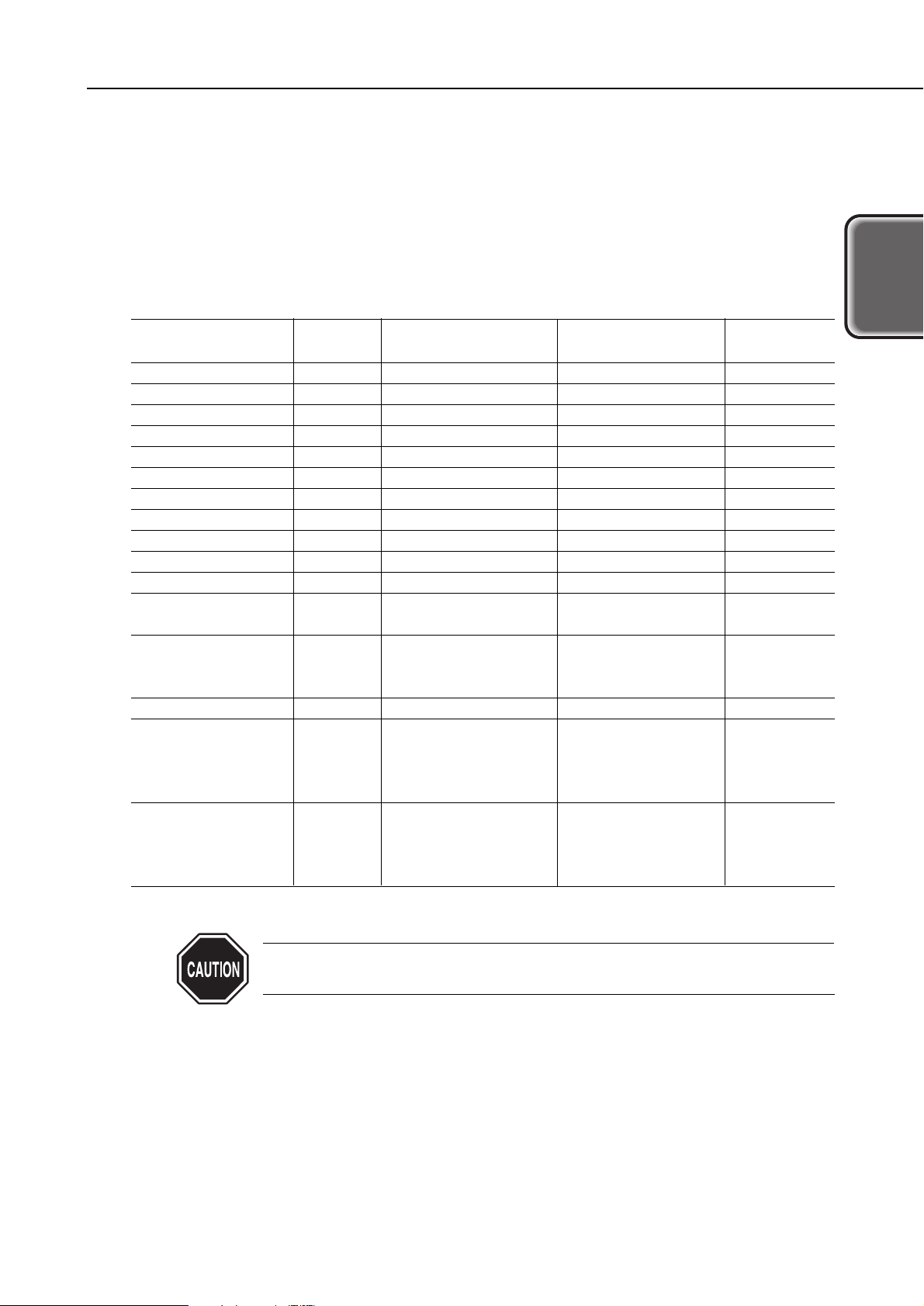
1 - 6 Figure 1 - 4 Printable Area
1 - 8 Figure 1 - 5 Packing Configuration
Part 2: TROUBLESHOOTING
2 - 1 Figure 2 - 1 Operation Panel
2 - 3 Figure 2 - 2 Nozzle Check Pattern Printout
2 -14 Figure 2 - 3 Exploded View
2 -15 Figure 2 - 4 Carriage Lock Release
2 -16 Figure 2 - 5 Encoder Film
2 -17 Figure 2 - 6 Short-Circuiting the Capacitor
2 -18 Figure 2 - 7 Do not Remove the Red Screws
2 -18 Figure 2 - 8 Installing the Logic Board Cover
2 -19 Figure 2 - 9 Handling the Purge Unit
2 -20 Figure 2 -10 Installing the ROM Cover
2 -22 Figure 2 -11 Applying Grease
2 -23 Figure 2 -12 Printing Position Adjustment Pattern
2 -24 Figure 2 -13 Seam Stripe Adjustment Pattern
2 -30 Figure 2 -14 Service/Factory Test Printout (Sample)
2 -31 Figure 2 -15 EEPROM Information Printout (Sample)
Part 3: TECHNICAL REFERENCE
3 - 1 Figure 3 - 1 Printing Signal Flow
3 - 2 Figure 3 - 2 Serial Data
3 - 3 Figure 3 - 3 Print Driving
3 - 4 Figure 3 - 4 Printing Driving Method
3 - 7 Figure 3 - 5 Location of Sensors
3 - 8 Figure 3 - 6 Ink Sensor
3 -10 Figure 3 - 7 Block Diagram
3 -12 Figure 3 - 8 Printer's Mechanical Parts
3 -15 Figure 3 - 9 Purge Section Components
3 -16 Figure 3 -10 Pump Operation
3 -17 Figure 3 -11 Paper Feeding
3 -19 Figure 3 -12 Control Board
3 -22 Figure 3 -13 Basic Settings Sheet (Sample)
3 -25 Figure 3 -14 Nozzle Array
Part 4: APPENDIX
4 - 1 Figure 4 - 1 Control Board
4 - 4 Figure 4 - 2 Carriage Board
4 - 6 Figure 4 - 3 BJ Cartridge
V

IV. TABLE INDEX
Page
Part 1: PRODUCT SPECIFICATIONS
1 - 9 Table 1- 1 PARTS CODE
Part 2: TROUBLESHOOTING
2 -10 Table 2- 1 ERROR INDICATIONS
Part 3: TECHNICAL REFERENCE
3 -24 Table 3 - 1 PRINTING MODE LIST
VI

Part 1
PRODUCT
SPECIFICATIONS
Page
1 - 1 1. PRODUCT OVERVIEW
1 - 1 1.1 Product Overview
1 - 3 2. SPECIFICATIONS
1 - 3 2.1 Printer Specifications
1 - 5 2.2 Paper Specifications
1 - 7 2.3 BJ Cartridge Specifications
1 - 7 2.4 Printer and Scanner Drivers
1 - 8 3. PACKING CONFIGURATION
1 - 9 4. PARTS CODE LIST

I. PRODUCT OVERVIEW
1.1 Product Overview
"Standard Color Printer for Personal Use"
With an emphasis on "out of the box performance," the printer is ready for high-speed,
high-quality printing on plain paper at the default settings.
This printer targets business users who need high-quality text printing or DTP
printouts and personal users who want high-speed printing or a good printer to print
information from the Internet.
1) High-speed, high-quality printing with a bi-directional, color, 1200 dpi, nozzle-pitch
printing head.
• Full-page color printing on plain paper is faster and of higher quality than rival
printers.
B/W text: 15 ppm (Fast Gear Pattern*1)
Color DTP: 10 ppm (Fast Gear Pattern*1)
Compared to: Color full address*2: 2.5 ppm (A4 full pattern*1)
• Color ink drop size is 5 pl.
2) High-quality printing with new inks
Pigment black: A black with better density (OD*3value of 1.4 or higher) makes high-
density text printing possible.
Color: Improved brilliance and better color density.
3) Base model for future printers
• The printer's engine (BJ cartridge and BJ cartridge drive system) will be standard
equipment on future BJ printers.
• The printer's other systems (carriage system, paper transport system, ASF, purge
system) have a modular design so they can easily be used in successor or sister
models.
• The ASF uses a new system (Duopro*4) marking a major improvement in paper feed
power. Paper transport strength.
4) The DC motor (carriage and paper feed) makes printing quiet.
5) Compact design.
6) Compatible with Windows 95/98/NT 4.0/2000 and Mac OS 8.1 or higher.
*1: Standard pattern introduced in 2000 for printing speed measurements.
*2: On A4-size paper, each dot is printed at 1200 × 1200 dpi intervals.
*3: Optical Density.
*4: Separation system based on the friction between paper sheets, paper and pad, and
paper and the paper transport roller of the separation pad.
1-1
S600
Part 1: Product Specifications
Product
Specifications
Part 1: Product Specifications
S600
1-2
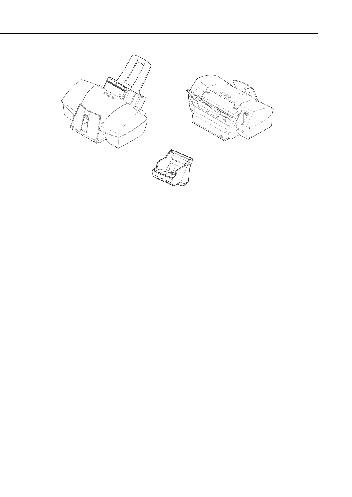
Printer (Front) Printer (Rear)
BJ Cartridge (Print Head)
Figure 1-1 Printer Exterior
2. SPECIFICATIONS
2.1 Printer Specifications
2.1.1 Printer specifications
1-3
S600
Part 1: Product Specifications
Product
Specifications
Type
Paper Feed System
Resolution
Throughput
Printing Direction
(Plain/Special
paper)
Max. Printing Width
Interface
ASF Capacity
Sensors
Operating Noise (at
HQ)
Ambient Conditions
Power Source
External
Dimensions
Weight
Certification
(Printer & adapter)
Serial No. Location
Desktop serial printer
Automatic feed only (No manual feed)
2400 × 1200 dpi (Max. resolution)
Bk: 15 ppm
Color: 10 ppm
HS mode (600 dpi × 600 dpi...): Single-pass bi-directional
HQ mode (600 dpi × 600 dpi/1200 dpi × 1200 dpi):
Single-pass unidirectional/double- or triple-pass bi-directional
Fine1 mode (1200 dpi × 1200 dpi/As above):
1.2-pass unidirectional/4- or 6-pass bi-directional
Fine2 mode (As above/As above):
4-pass bidirectional/4-pass unidirectional or bi-directional
Fine3 mode (.../2400 dpi × 1200 dpi):
4-pass unidirectional or 6-pass bi-directional
203 mm (8 in.) wide
IEEE 1284-standard, 8-bit parallel, USB (No HUB function)
Plain paper: Max. 10 mm (Approx. 100 sheets with 75 g/m2or
approx. 110 sheets with 64 g/m2)
Front cover-open sensor, BJ cartridge-loaded sensor, No-ink
sensor, Printing position sensor, Paper sensor (paper out detector),
Waste-ink capacity sensor, Internal temperature sensor, Pick-up
roller sensor, Paper-feed roller position sensor, Carriage position
sensor, Paper interval sensor
39 dB (A) Sound pressure level conforms to ISO 9296.
During operation: Temperature 5°C-35°C (41°F-95°F)
Humidity 10%-90% RH (No condensation)
During non-operation: Temperature 0°C-35°C (32°F-95°F)
Humidity 5%-90% RH (No condensation)
Power voltage/frequency Power consumption During standby When Off
100-127 VAC 50/60 Hz Max. approx. 40 W Approx. 3 W Approx. 1 W
220-240 VAC 50/60 Hz Max. approx. 40 W Approx. 3 W Approx. 1 W
Approx. 430 mm (W) × 294 mm (D) × 177 mm (H)
Approx. 5 kg (excluding BJ cartridge)
Radio wave interference: VCCI, FCC, IC, C-Tick, Taiwan/Korea
EMC, CCIB (EMC)/CCEE
Electrical safety: Electrical appliance regulation, UL, Cul,
CE Mark, TUV, FIMKO, SASO, AS, PSB,
Korean Electric Commerce, CB/CCIB/CCEE
Environmental: Energy Star, Blue Angel
Carriage ribbon cable holder (visible when the access cover is open)
2.1.2 Printer service life
Whichever comes first:
(1) A total of 30,000 sheets printed with 1,500 standard characters in black ink.
(2) A total of 10,000 sheets printed with 7.5% duty per color.
(3) Five years of use.
2.1.3 BJ cartridge service life
(1) Service life
For monochrome printing (1500-character standard text pattern printing): 30,000
pages
For color printing (7.5% duty pattern printing per color): 10,000 pages
(2) Ink tank service life (printable pages per tank)
Monochrome (black): 695 pages (1500 characters pattern*1/Printing quality:
Standard)
Color (Cyan): 460 pages (JIS SCID No. 5*2/Printing quality: Standard)
(Magenta): 395 pages ( As above )
(Yellow): 300 pages ( As above )
*1 Printing duty: Equivalent to 2.22% pattern
*2 Printing duty: Equivalent to 3.68% (cyan) pattern
Equivalent to 5.12% (magenta) pattern
Equivalent to 6.10% (yellow) pattern
Part 1: Product Specifications
S600
1-4
Figure 1-2 1500 Characters Pattern Figure 1-3 JIS SCID No. 5
1-5
S600
Part 1: Product Specifications
Product
Specifications
2.2 Paper Specifications
2.2.1 Paper sizes and weights
(1) Paper sizes
See the table below.
(2) Weight
For automatic feeding, the paper's weight should be 64-90 g/m2.
2.2.2 Paper types and settings
If the paper spacing lever is not properly set, problems with paper feeding
or printing may occur.
Type Size Sheet Feeder Capacity
Paper Spacing
Lever Position
Plain paper 64-90 g/m2A4/B5/A5/LTR/LGL Less than 10 mm Left (Narrow)
High-quality paper HR-101 A4/LTR Less than 80 sheets Left (Narrow)
Photo glossy paper GP-301 A4/LTR 10 sheets Left (Narrow)
Photo paper PR-101 A4/LTR 1 sheet Left (Narrow)
Glossy film HG-201 A4/LTR 1 sheet Left (Narrow)
Transparency film CF-102 A4/LTR Less than 30 sheets Left (Narrow)
Banner BP-101 A4/LTR 1 sheet Right (Wide)
T-shirt transfer TR-201 A4/LTR 1 sheet Right (Wide)
Mouse pad MK-101 --- 1 sheet Left (Narrow)
Glossy postcard KH-201 148 mm × 100 mm Less than 20 Left (Narrow)
Photo glossy card FM-101 118.6 mm × 213.9 mm Less than 20 Left (Narrow)
Japan Post Office
postcard
--- 148 mm × 100 mm Less than 40 Left (Narrow)
Japan Post Office
postcard for ink jet
printing
--- 148 mm × 100 mm Less than 40 Left (Narrow)
Pro photo postcard PH-101 148 mm × 100 mm Less than 20 Left (Narrow)
Envelope COM#10 241 mm × 106 mm Less than 10 Right (Wide)
DL-size 220 mm × 110 mm Less than 10 Right (Wide)
No. 4 235 mm × 105 mm Less than 10 Right (Wide)
No. 6 190 mm × 98 mm Less than 10 Right (Wide)
Pro photo card PC101 L 101.6 mm × 190.5 mm Less than 20 Left (Narrow)
PC101 2L 210 mm × 183 mm Less than 10 Left (Narrow)
PC101 D 210 mm × 310 mm Less than 10 Left (Narrow)
PC101 W 210 mm × 310 mm Less than 10 Left (Narrow)
2.2.3 Printing area
Part 1: Product Specifications
S600
1-6
■ Pro Photo Card
■ Envelope (No. 4/No. 6)
PC-101 L: L size PC-101 2L: 2L size
Recommended
printing area:
Printable area:
■ A4, B5, A5
■ Glossy postcard/Japan Post Office postcard/Japan Post
Office postcard forink jet printing/Pro photo postcard
■ Photo glossy card
PC-101 D: DCS size cut into 4 PC-101 W: 8x10 in. for digital cameras
5.0 mm
3.4 mm
±1.5*
1
3.4 mm
±1.5
26.5 mm
28.0 mm
3.0 mm
±1.5*
1
5.0 mm
6.4 mm
±1.5
6.4 mm
±1.5
26.5 mm
28.0 mm
3.0 mm
±1.5
3.0 mm
±3.0
26.5 mm
3.4 mm
±2.0
3.4 mm
±2.0
3.0 mm
±1.5
5.0 mm
3.4 mm
±1.5
3.4 mm
±1.5
28.0 mm
26.0 mm*
2
5.1 mm
4.1 mm
28.8 mm
3.3 mm
3.3 mm
28.8 mm
25.0 mm*
2
13.0 mm
13.0 mm
25.0 mm
29.0 mm
9.0 mm
9.0 mm
29.0 mm
25.0 mm
7.0 mm
7.0 mm
25.0 mm
()
()
()
()
*1 For recycled paper, it will be 3.0mm ±3 or 3.4mm ±2.
*2 If the bottom margin goes beyond the plain paper's printable area, the software application's specifications
will apply.
The region inside the dotted lines is the printable area where print quality can be guaranteed.
Note: The right margins in parentheses indicate that the dimension depends on the paper size.
Paper-feeding direction
■ Letter
Figure 1-4 Printable Area

2.3 BJ Cartridge Specifications
2.4 Printer and Scanner Drivers
The user interface of the drivers has been greatly improved. See page 3-22 for details.
1 Windows drivers
Win95/98/ME BJ raster driver (V. 7.00)
Win9NT4.0 BJ raster driver (V. 4.30)
Win2000 BJ raster driver (V. 1.30)
2 Macintosh driver
Mac BJ printer driver (V. 3.71)
3 Scanner driver
None.
1-7
S600
Part 1: Product Specifications
Product
Specifications
Configuration
Print Head
Ink Colors*
Ink Tank
Weight (Net value)
BJ Cartridge (Print Head)
Detachable ink tanks for each color and BK/Cl (C, M, Y)
integrated head
BK: 320 nozzles, 2-column vertical array
Cl: 256 nozzles/color, 2-column vertical array/color
Pigment BK, dyes C, M, Y
BCI-3eBK, BCI-3eC, BCI-3eM, BCI-3eY
BK: 32 g Cl (C, M, Y): 11 g
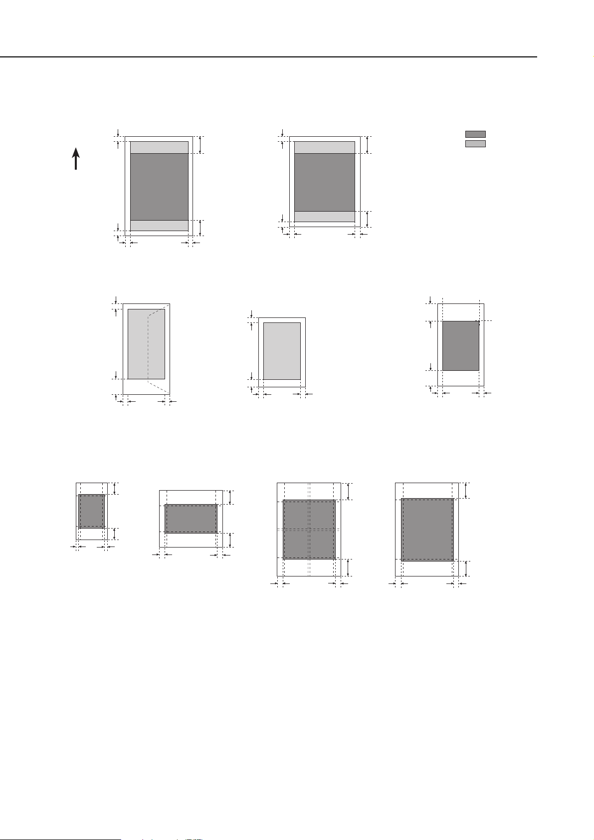
3. PACKING CONFIGURATION
After opening the box, make sure all the items below are included.
There is no storage box for storing the BJ cartridge.
Part 1: Product Specifications
S600
1-8
Output Tray
Power Cord
Ink Tank
Ink Tanks
Instruction Manuals
Printer
BJ Cartridge
Figure 1-5 Packing Configuration
4. PARTS CODE LIST
A list of printer parts, consumables, and optional equipment are listed below.
The printer's BJ cartridge (print head) will be supplied only as a spare part for servicing.
*1 Supplied only as a spare part for servicing. It will not be supplied as a consumable or
optional part.
1-9
S600
Part 1: Product Specifications
Product
Specifications
Table 1-1 PARTS CODE
Item
Printer
BJ cartridge*
1
Ink tank
---
--Black
Cyan
Magenta
Yellow
Designation
S600
BJ S600
--BCI-3eBK
BCI-3eC
BCI-3eM
BCI-3eY
Parts Code
Q30-3380 (CCSEK)
Q30-3382 (HK/TW)
Q30-3381
QY6-0034
F47-3131
F47-3141
F47-3151
F47-3161

Part 2
TROUBLESHOOTING
Page
2 - 1 1. PRINTER OPERATION
2 - 1 1.1 Printer Operation Procedure
2 - 1 1.2 Status Indicator
2 - 2 1.3 Operating the Printer
2 - 5 2. SERVICING
2 - 5 2.1 Before Troubleshooting
2 - 6 2.2 Detectable Problems from System Start to Exit
2 - 9 2.3 Troubleshooting Problems
2 -10 2.4 Troubleshooting Error Indications
2 -13 3. DISASSEMBLY AND REASSEMBLY
2 -13 3.1 Cautions for Disassembly and Reassembly
2 -14 3.2 Exploded View
2 -15 3.3 Disassembly and Reassembly
2 -21 3.4 Adjustments and Settings After Disassembly and Reassembly
2 -26 4. OPERATION CHECK AFTER DISASSEMBLY AND REASSEMBLY
2 -26 4.1 Check Procedure
2 -27 5. TRANSPORTING THE PRINTER
2 -27 5.1 Procedure
2 -28 6. PARTS REPLACEMENT, PERIODIC INSPECTIONS, & TOOLS
2 -28 6.1 Parts Replacement
2 -28 6.2 Periodic Inspections
2 -28 6.3 Tool List
2 -29 7. SERVICE-RELATED FEATURES
2 -29 7.1 Service Mode Operations
2 -30 7.2 Test Printout
2 -31 7.3 Printing the EEPROM Information
2 -32 7.4 Resetting the EEPROM
2 -32 7.5 Setting the Printer Settings in the EEPROM
1. PRINTER OPERATION
The printer's operation procedures are explained below. You can operate the printer
either by itself or with a computer. Both methods are explained below.
1.1 Printer Operation Procedure
The printer's operation panel has a
POWER
button and a
RESUME
button to cancel
printing operation or to cancel an error. With a computer, you can use the printer
driver to adjust the print head's position and to change various settings. For details on
using the printer driver with the computer, see page 3-22.
1.2 Status Indicator
When you operate the printer by itself, you can find out the printer's operation status
with the indicator. When an error occurs, the nature of the error can be determined by
the number of times the indicator blinks.
Normal Operation
Error
2-1
S600
Part 2: Troubleshooting
Tr oubleshooting
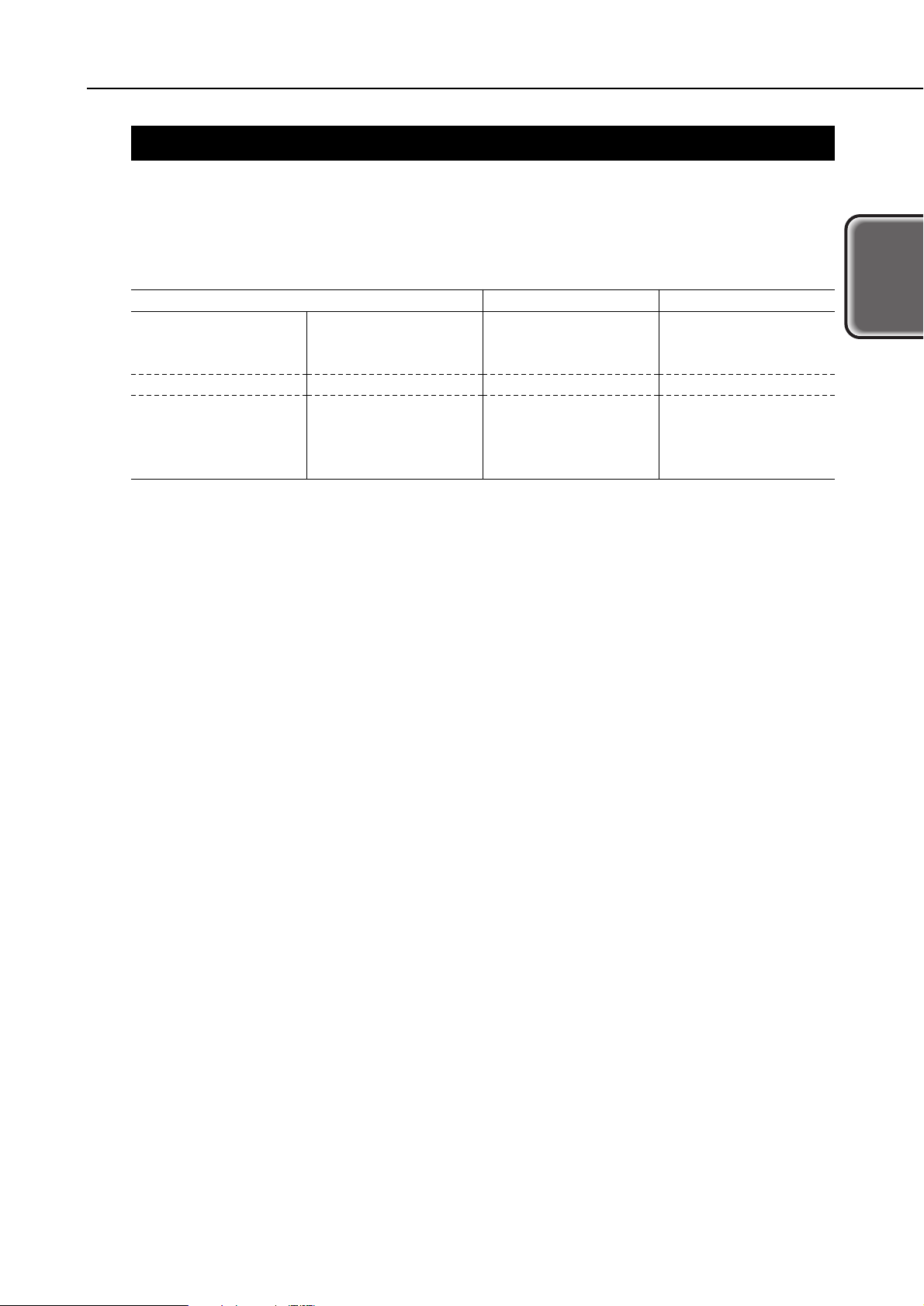
Indicator Display
Green light
Blinks green
(Long/short)
Light off
Operation Status
Power ON
Power ON in progress, power OFF in progress, resume
operation in progress, cleaning in progress, test printing in
progress, front cover open, printing in progress
Power OFF
Indicator Display
Blinks orange
(Long/short)
Green/orange
(Toggle blinking)
Operation Status
The number of blinks differs depending on the error. See page
2-10 for details.
The blinking method differs depending on the error. See page
2-11 for details.
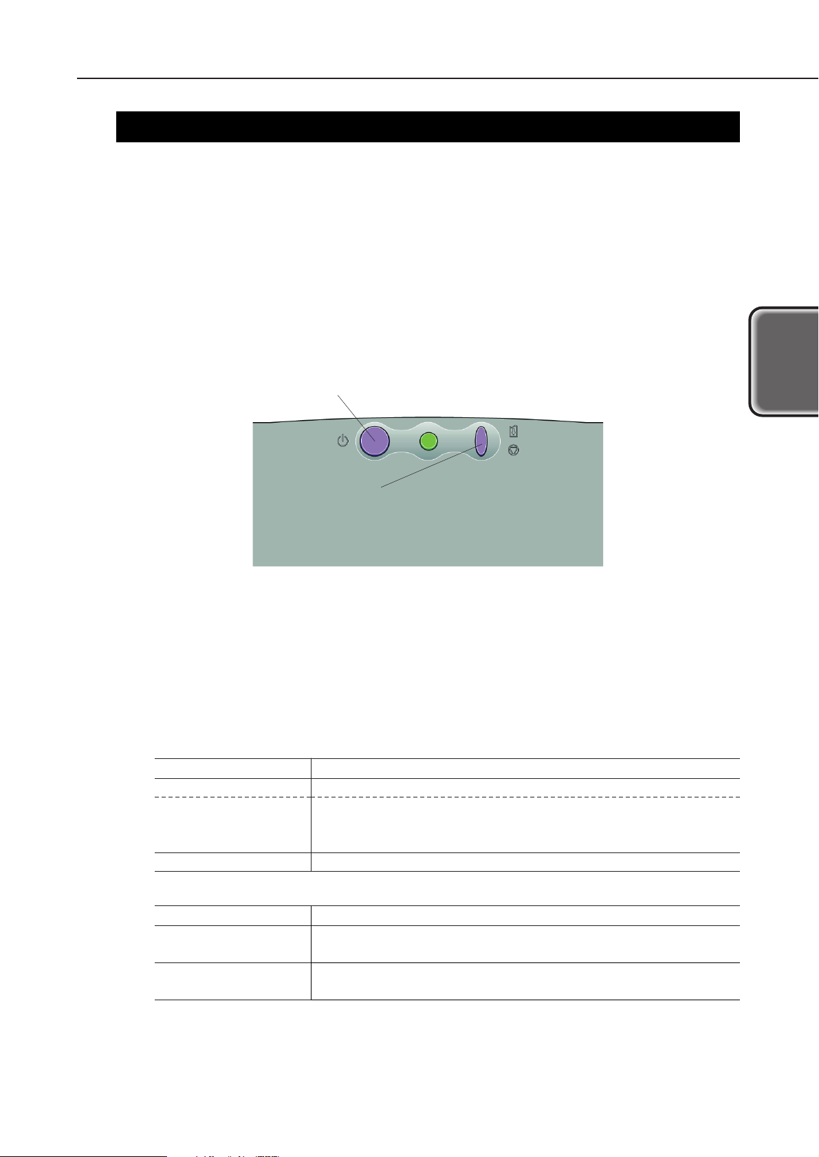
POWER button
Turns the printer ON/OFF and cancels
test printing.
RESUME button
Cancels printing operation or an error.
The cleaning and nozzle check pattern can be selected
by the number of blinks of the indicator.
Figure 2-1 Operation Panel

1.3 Operating the Printer
The printer has an offline operation mode that works when the printer is not connected
to a computer and the power is on.
To conduct the operations below, with the power turned on, hold down the
RESUME
button until the green indicator blinks for the specified number of times.
1.3.1 Cleaning operation
To start the cleaning operation, turn on the printer and hold down the
RESUME
button
until the green indicator blinks once. Then let go of the button. Cleaning will then start.
The black and color ink nozzles will be cleaned simultaneously by suction. This is the
same as using the printer driver to clean all of the ink nozzles.
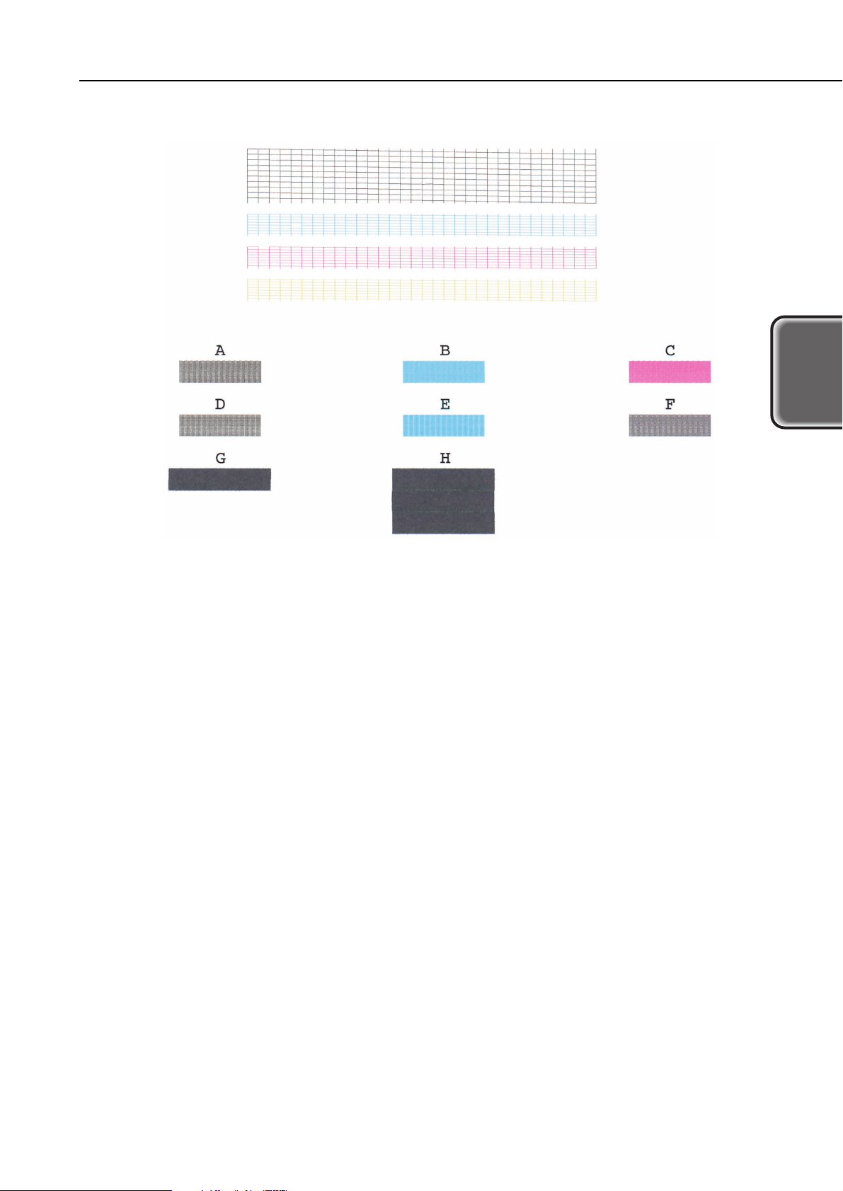
1.3.2 Printing the nozzle check pattern
With the printer turned on, hold down the
RESUME
button until the green indicator
blinks twice. The printer will then start printing the nozzle check pattern. If any
printing flaws show up in this test printout, clean the BJ cartridge.
Printing the nozzle check pattern requires B5 or larger paper. If the
paper's width is narrower than the nozzle check pattern, the printer will
print on the bare platen, dirtying the platen with ink.
To stop printing of the test pattern midway, press the
POWER
button.
Printing will stop and the paper will be ejected. The printer will remain on.
If the problem persists even after cleaning the BJ cartridge three times,
Perform Deep Cleaning of from the driver. If that still does not resolve the
problem, replace the BJ cartridge.
Part 2: Troubleshooting
S600
2-2
Operation
Cleaning operation
Nozzle check pattern
printing
Roller cleaning
operation
---
Indicator Blink Count
Once
Twice
3 times
4 times
Remarks
--Load a sheet of B5 or larger
paper.
Load no paper or load A4 paper.
Execute no operations.
2-3
S600
Part 2: Troubleshooting
Tr oubleshooting
Figure 2-2 Nozzle Check Pattern Printout

1.3.3 Roller cleaning operation
This is to remove the paper dust adhering to the auto sheet feeder's rollers. With the
printer turned on, hold down the
RESUME
button until the green indicator blinks once.
The cleaning of the rollers will then start.
There are two cleaning methods:
(1) Passing plain paper through
Place a sheet of plain paper on the auto sheet feeder and execute roller cleaning.
Do this three times.
(2) Rotating the rollers without paper
Execute roller cleaning without placing any paper on the auto sheet feeder.
(The rollers will rotate ten times.)
Do this three times.
Do not execute the cleaning operation more times than necessary.
Excessive cleaning will generate rubber dust which can affect the printer's
operation.
Part 2: Troubleshooting
S600
2-4
2. SERVICING
2.1 Before Troubleshooting
Before troubleshooting, check the following and see if any of the applicable problems
can be fixed.
2-5
S600
Part 2: Troubleshooting
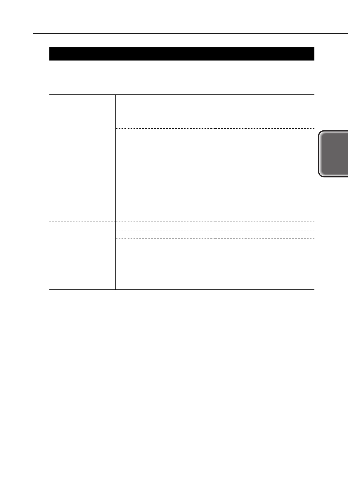
Tr oubleshooting
Problem
The printer does not
operate at all.
Paper feeding does
not work.
No printing.
Stripes appear in the
printout.
Probable Cause
The power outlet is not supplying
the required voltage.
The power cord is not properly
connected to the printer or power
outlet.
An internal plug is disconnected.
The recommended paper is not
being used.
There is foreign matter in the
paper feed section (sheet feeder,
pinch roller, LF roller, platen,
spur).
The BJ cartridge needs cleaning.
The ink cartridge is empty.
The BJ cartridge has not been
used for a prolonged period.
The print head position has not
been adjusted.
Solution
Connect the AC cord to a power
outlet which supplies the
required voltage.
Check that the power cord is
connected properly.
Disconnect and reconnect the
plug.
Use the recommended paper.
Remove the foreign matter.
Clean the BJ cartridge.
Replace the ink cartridge.
Clean the cartridge. If the
problem still persists, replace the
cartridge.
Execute print head position
adjustment.
See page 2-23.
Loading...