


 Loading...
STAPLER SORTER-H1
SERVICE
MANUAL
REVISION 0
DEC. 1997 |
FY8-13F5-000 |
COPYRIGHT © 1997 CANON INC. |
CANON STAPLER SORTER-H1 REV.0 DEC. 1997 PRINTED IN JAPAN (IMPRIME AU JAPON) |

IMPORTANT
THE INFORMATION CONTAINED HEREIN IS PUBLISHED BY CANON, INC., JAPAN, AND IS FOR REFERENCE USE ONLY. SPECIFICATIONS AND OTHER INFORMATION CONTAINED HEREIN MAY VARY SLIGHTLY FROM ACTUAL MACHINE VALUES OR THOSE FOUND IN ADVERTISING AND OTHER PRINTED MATTER.
ANY QUESTIONS REGARDING INFORMATION CONTAINED HEREIN SHOULD BE DIRECTED TO THE COPIER SERVICE DEPARTMENT OF THE SALES COMPANY.
COPYRIGHT © 1997 CANON INC.
Printed in Japan
Imprimé au Japon
Use of this manual should be
strictly supervised to avoid
disclosure of confidential
information
Prepared by
OFFICE IMAGING PRODUCTS TECHNICAL SUPPORT DEPARTMENT 1 OFFICE IMAGING PRODUCTS TECHNICAL SUPPORT DIVISION
CANON INC.
5-1, Hakusan 7-chome, Toride-shi, Ibaraki, 302 Japan
COPYRIGHT © 1997 CANON INC. |
CANON STAPLER SORTER-H1 REV.0 DEC. 1997 PRINTED IN JAPAN (IMPRIME AU JAPON) |

INTRODUCTION
This Service Manual provides basic facts and figures needed to service the Stapler Sorter-H1 in the field and consists of the following:
Chapter 1 “General Descriptions” shows features, specifications, and names of external parts and how to operate the sorter.
Chapter 2 “Operations and Timing” discusses the sorter’s mechanical and electrical systems by function and various timing of operation.
Chapter 3 “Mechanical System” shows how to disassemble, assemble, and adjust the sorter. Chapter 4 “Maintenance and Inspection” gives lists of periodically replaced parts and consumables/
durables and a scheduled servicing chart.
Chapter 5 “Troubleshooting” shows how to troubleshoot possible faults and gives electrical parts arrangement diagrams, VR/LED/check pin diagrams by PCB, and self diagnosis tables.
In addition to the above chapters, this Service Manual contains an Appendix consisting of a general timing chart, a signals/abbreviations list, communications signals list, a General circuit diagram controller circuit diagrams, special tools list, and solvent/oils list.
For installation, refer to the Installation Procedure that comes with the Sorter Mounting Kit.
COPYRIGHT © 1997 CANON INC. |
CANON STAPLER SORTER-H1 REV.0 DEC. 1997 PRINTED IN JAPAN (IMPRIME AU JAPON) |
i
ii
COPYRIGHT © 1997 CANON INC. |
CANON STAPLER SORTER-H1 REV.0 DEC. 1997 PRINTED IN JAPAN (IMPRIME AU JAPON) |

CONTENTS
CHAPTER 1 GENERAL DESCRIPTION
I. |
FEATURES.............................................. |
1-1 |
IV. OPERATION............................................ |
1-7 |
||
II. |
SPECIFICATIONS ................................... |
1-2 |
A. |
Operation Panel................................ |
1-7 |
|
III. |
NAMES OF PARTS ................................. |
1-5 |
B. |
Stapling............................................. |
1-8 |
|
|
A. |
External View ................................... |
1-5 |
C. Resupply of Staples to Stapler....... |
1-10 |
|
|
B. |
Cross Section ................................... |
1-6 |
D. Removing a Staple Jam ................. |
1-12 |
|
|
|
|
|
E. |
Removing Paper Clogging ............. |
1-13 |
CHAPTER 2 OPERATIONS AND TIMING
I. |
CONSTRUCTION.................................... |
2-1 |
IV. |
STAPLER UNIT DRIVE SYSTEM |
.........2-24 |
||
|
A. |
Functional Construction.................... |
2-1 |
|
A. |
Outline ............................................ |
2-24 |
|
B. |
Electrical Circuitry............................. |
2-2 |
|
B. |
Stapler Unit..................................... |
2-26 |
|
C. |
Sorter Controller Input/Output .......... |
2-3 |
|
C. |
Controlling the Swinging |
|
|
D. |
Communication between Copier |
|
|
|
Movement of the Stapler Unit......... |
2-32 |
|
|
and Sorter......................................... |
2-6 |
|
D. |
Holding the Paper........................... |
2-36 |
II. |
BASIC OPERATIONS.............................. |
2-7 |
|
E. |
Stapling Operation Timing.............. |
2-37 |
|
|
A. |
Outline .............................................. |
2-7 |
V. |
BIN UNIT DRIVE SYSTEM ................... |
2-38 |
|
|
B. |
Basic Operations .............................. |
2-9 |
|
A. |
Outline ............................................ |
2-38 |
III. |
FEED DRIVE SYSTEM ......................... |
2-16 |
|
B. |
Bin Unit........................................... |
2-39 |
|
|
A. |
Outline ............................................ |
2-16 |
|
C. Controlling the Guide Bar............... |
2-44 |
|
|
B. Controlling the Feed Speed............ |
2-18 |
|
D. Sensors Inside Bin Unit.................. |
2-47 |
||
|
C. |
Over Stack Condition ..................... |
2-19 |
|
E. |
Other Sensors ................................ |
2-48 |
|
D. |
Jam................................................. |
2-22 |
VI. |
POWER SUPPLY .................................. |
2-49 |
|
CHAPTER 3 MECHANICAL SYSTEM
I. |
EXTERNALS ........................................... |
3-1 |
|
|
A. |
External Covers................................ |
3-1 |
|
B. |
Feed Guide Unit ............................... |
3-2 |
II. |
BIN UNIT ................................................. |
3-3 |
|
|
A. Detaching the Bin Unit ..................... |
3-3 |
|
|
B. |
Detaching the Bin ............................. |
3-6 |
|
C. Detaching the Bin Shift Motor |
|
|
|
|
(M1) ................................................ |
3-11 |
|
D. |
Lead Cam....................................... |
3-12 |
|
E. Detaching the Guide Bar Motor |
|
|
|
|
(M3) ................................................ |
3-16 |
III. |
FEED GUIDE UNIT ............................... |
3-17 |
|
A. Detaching the Feed Guide Unit...... |
3-17 |
|
B. Detaching the Feed Motor (M2) ..... |
3-18 |
|
C. Detaching the Feed Roller.............. |
3-19 |
IV. |
STAPLER UNIT ..................................... |
3-20 |
|
A. Detaching the Stapler Unit ............. |
3-20 |
V. |
STAPLER SWING UNIT........................ |
3-21 |
|
A. Detaching the Stapler Unit |
|
|
Swing Motor (M4) ........................... |
3-21 |
|
B. Detaching the Stapler Swing Unit .. |
3-22 |
COPYRIGHT © 1997 CANON INC. |
CANON STAPLER SORTER-H1 REV.0 DEC. 1997 PRINTED IN JAPAN (IMPRIME AU JAPON) |
iii

CHAPTER 4 MAINTENANCE AND INSPECTION
I. |
PERIODICALLY REPLACED PARTS...... |
4-1 |
III. PERIODICAL SERVICING ...................... |
4-1 |
II. |
CONSUMABLES ..................................... |
4-1 |
|
|
CHAPTER 5 TROUBLESHOOTING
I. |
STANDARDS AND ADJUSTMENTS |
.........5-1 |
IV. |
PCB ....................................................... |
5-18 |
||
|
A. |
Electrical System.............................. |
5-1 |
|
F. |
Dip Switch Function List ................. |
5-19 |
|
B. |
Mechanical System .......................... |
5-7 |
V. |
SELF DIAGNOSIS................................. |
5-20 |
|
II. |
TROUBLESHOOTING ........................... |
5-9 |
|
A. |
Stack Over Alarm ........................... |
5-20 |
|
|
A. |
Procedure ......................................... |
5-9 |
|
B. |
Stapler Alarm.................................. |
5-20 |
III. |
ELECTRICAL PARTS LAYOUT |
|
|
C. |
Jam................................................. |
5-21 |
|
|
DIAGRAM .............................................. |
5-14 |
|
D. |
Error................................................ |
5-22 |
|
|
A. |
Sensors .......................................... |
5-14 |
|
|
|
|
B.Motors, Switches, Solenoids,
PCBs .............................................. |
5-16 |
APPENDIX
A. |
TIMING CHART ....................................... |
A-1 |
C. LIST OF COMMUNICATION |
|
B. |
SIGNAL NAME/ABBREVIATION LIST..... |
A-5 |
DATA/SIGNAL WITH COPIER ............... |
A-15 |
iv
COPYRIGHT © 1997 CANON INC. |
CANON STAPLER SORTER-H1 REV.0 DEC. 1997 PRINTED IN JAPAN (IMPRIME AU JAPON) |

CHAPTER 1
GENERAL DESCRIPTION
I. |
FEATURES.............................................. |
1-1 |
IV. OPERATION............................................ |
1-7 |
||
II. |
SPECIFICATIONS ................................... |
1-2 |
A. |
Operation Panel................................ |
1-7 |
|
III. |
NAMES OF PARTS ................................. |
1-5 |
B. |
Stapling............................................. |
1-8 |
|
|
A. |
External View ................................... |
1-5 |
C. Resupply of Staples to Stapler....... |
1-10 |
|
|
B. |
Cross Section ................................... |
1-6 |
D. Removing a Staple Jam ................. |
1-12 |
|
|
|
|
|
E. |
Removing Paper Clogging ............. |
1-13 |
COPYRIGHT © 1997 CANON INC. |
CANON STAPLER SORTER-H1 REV.0 DEC. 1997 PRINTED IN JAPAN (IMPRIME AU JAPON) |

1. GENERAL DESCRIPTION
I. FEATURES
1. Light-weight, compact design
In comparison with the existing 20-bin stapler sorters, the size, weight and number of components of this model have been remarkably reduced, while securing the loadability over equivalence to the former models. Reliability and serviceability have been also improved.
2. Applicable to multiple types of copiers
Straight path communication system of this model allows it to be adapted to multiple types of copiers. (Communication can be switched between the new and former IPCs. Allowable speed range is 20 ~
60 cpm.)
COPYRIGHT © 1997 CANON INC. |
CANON STAPLER SORTER-H1 REV.0 DEC. 1997 PRINTED IN JAPAN (IMPRIME AU JAPON) |
1–1 |

1.GENERAL DESCRIPTION
II.SPECIFICATIONS
Item |
Spec. |
Remarks |
|
|
|
|
|
Loading |
Face up, bin shift and open |
|
|
|
|
|
|
No. of bins |
20 |
|
|
|
|
|
|
Capacity per bin: *1 |
Non sort mode: |
|
|
equivalent to 80 g/cm2 |
600 copies |
(A4, LTR, B5, STMT, |
30 copies/bin *2 |
|
|
A4R, LTR-R, B5R) |
|
|
500 copies |
(A3, 11" × 17", B4, LGL) |
25 copies/bin |
|
Sort mode: |
|
|
|
50 copies |
(A4, LTR, B5, A5, STMT, |
|
|
|
A4R, LTR-R, B5R) |
|
|
25 copies |
(A3, 11" × 17", B4, LGL) |
|
|
Staple sort mode: |
|
|
|
50 copies |
(A4, LTR, B5, A4R, LTR-R) |
Unavailable to |
|
|
(A3, 11" × 17", B4, LGL) |
B5R, STMT, A5 |
|
25 copies |
|
|
|
Group mode: |
|
|
|
30 copies |
(A4, LTR, B5, A5, STMT, |
|
|
|
A4R, LTR-R, B5R) |
|
|
25 copies |
(A3, 11" × 17", B4, LGL) |
|
|
|
|
|
Bin return time |
Approx. 10 sec. |
|
|
(from 20th to 1st bin) |
|
|
|
|
|
|
|
Limitless function |
Available |
|
|
|
|
|
|
Bin designation function |
Unavailable |
|
|
|
|
|
|
Control panel |
STAPLE key |
|
|
|
|
|
|
Display panel |
STAPLE RESUPPLY indicator |
|
|
|
|
|
|
Stapling |
Rotating cam |
|
|
|
|
|
|
Copy paper size for |
A3, A4, B4, B5, A4R,11" × 17", LGL, LTR, LTR-R |
|
|
auto stapling |
|
|
|
|
|
|
|
*1. Capacity per bin may vary depending on restrictions on the host copier.
*2. When the copies are below 100 sheets, all of them are loaded into the first bin.
1–2 |
COPYRIGHT © 1997 CANON INC. |
CANON STAPLER SORTER-H1 REV.0 DEC. 1997 PRINTED IN JAPAN (IMPRIME AU JAPON) |

1. GENERAL DESCRIPTION
Item |
Spec. |
||
|
|
|
|
Size of copies (for |
A3, A4, B4, B5, A4R, 11” × 17”, LGL, LTR, LTR-R |
||
manual stapling by key |
|
||
operation after copying |
|
||
process) |
|
|
|
|
|
|
|
Size of copies (for |
Any size |
||
manual insertion and |
|
||
stapling by user) |
|
||
|
|
|
|
No. of |
|
Automatic |
50 copies: A4, LTR, B5, A4R, LTR-R |
copies |
|
stapling |
25 copies: A3, 11" × 17", B4, LGL |
(for |
|
|
|
stapling |
|
|
|
paper |
|
|
|
equivalen |
|
|
|
t to 80 |
|
|
|
g/m2) |
|
|
|
|
Manual |
50 copies: A4, LTR, B5, A4R, LTR-R |
|
|
|
||
|
|
stapling |
25 copies: A3, 11" × 17", B4, LGL |
|
|
|
|
|
|
Manually |
30 copies: any size |
|
|
fed paper |
|
|
|
stapling |
|
|
|
|
|
Staple |
|
Staple for specific use (refilling type, 5,000 staples) |
|
|
|
|
|
No staple detection |
Available (when remaining staples are below 40 after |
||
|
|
|
the stapling process, NO STAPLE indicating lamp lights |
|
|
|
up) |
|
|
|
|
Automatic staple |
Available (after staples are resupplied and the stapler |
||
feeding |
|
unit cover is closed, the staples are automatically fed to |
|
|
|
|
the stapling position) |
|
|
|
|
Operating |
|
Temperature |
As per copier |
environm |
|
|
|
|
Humidity |
As per copier |
|
ent |
|
||
|
|
|
|
Power supply |
24V (from copier) |
||
|
|
|
|
Max. power |
|
Approx. 50W |
|
consumption |
|
|
|
|
|
|
|
Serial No. |
|
ZRVxxxxx |
|
|
|
|
|
Weight |
|
Approx. 20kg |
|
|
|
|
|
Dimensions |
|
348 × 595 × 626 [mm] |
|
(W × D × H) |
|
|
|
|
|
|
|
Remarks
48 copies of 80 g/cm2 paper + 2 copies of 200g paper or bundle of paper below 5.5mm in thickness
48 copies of 80 g/cm2 paper + 2 copies of 200g paper or bundle of paper below 5.5mm in thickness
COPYRIGHT © 1997 CANON INC. |
CANON STAPLER SORTER-H1 REV.0 DEC. 1997 PRINTED IN JAPAN (IMPRIME AU JAPON) |
1–3 |
1. GENERAL DESCRIPTION
Item |
|
Spec. |
Staple position |
|
|
|
6±2mm |
Feed direction |
|
|
|
|
|
6±2mm |
|
|
15˚ |
1–4 |
COPYRIGHT © 1997 CANON INC. |
CANON STAPLER SORTER-H1 REV.0 DEC. 1997 PRINTED IN JAPAN (IMPRIME AU JAPON) |
1. GENERAL DESCRIPTION
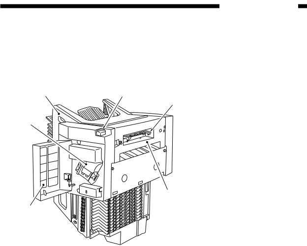
III. NAMES OF PARTS
A. External view
q |
t |
y
e
r
w
q Bin unit
w Stapler unit cover e Stapler unit
r Feed guide unit t Latch lever
y Latch
Figure 1-301
COPYRIGHT © 1997 CANON INC. |
CANON STAPLER SORTER-H1 REV.0 DEC. 1997 PRINTED IN JAPAN (IMPRIME AU JAPON) |
1–5 |
1. GENERAL DESCRIPTION
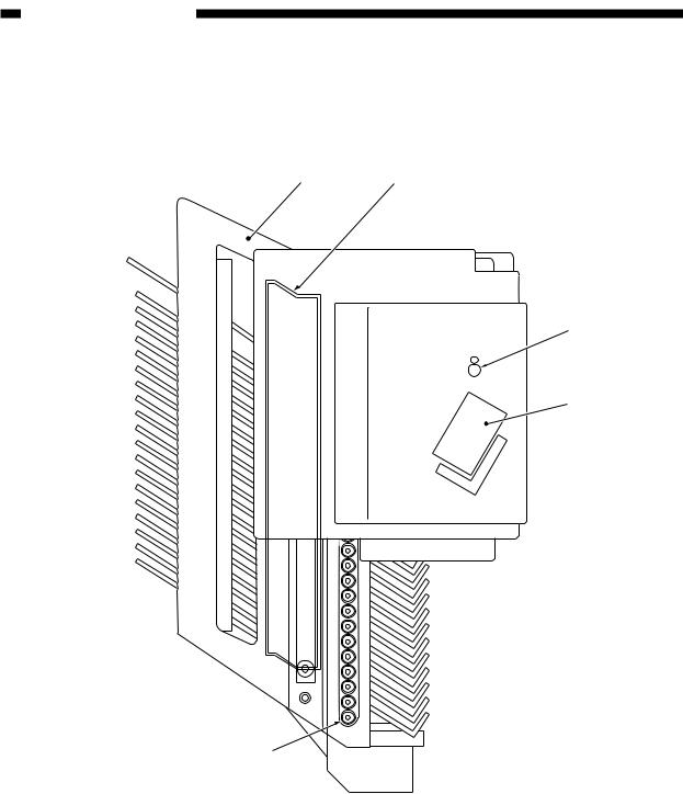
B. Cross section
q w
t
r
q Bin unit |
|
w Guide bar |
|
e Roll |
|
r Stapler unit |
e |
t Feed roller |
|
Figure 1-302
1–6 |
COPYRIGHT © 1997 CANON INC. |
CANON STAPLER SORTER-H1 REV.0 DEC. 1997 PRINTED IN JAPAN (IMPRIME AU JAPON) |
1. GENERAL DESCRIPTION
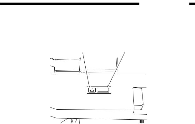
IV. OPERATION
A. Operation panel
w q
Figure 1-401
No. |
Name of key |
Function |
Remarks |
|
|
|
|
1 |
Staple key |
Pressed to start "manual stapling" or "manual |
The process |
|
|
insertion/stapling" process. |
cannot be |
|
|
If the key is pressed during the stapling process, |
discontinued |
|
|
the process is discontinued. |
during the manual |
|
|
The lamp blinks when the staple jam occurs in the |
insertion/stapling |
|
|
stapler. |
process |
|
|
|
|
2 |
STAPLE |
The lamp lights up when the staples in the stapler |
When remaining |
|
RESUPPLY |
have exhausted. |
staples after the |
|
indicator |
|
stapling process |
|
|
|
are below 40. |
|
|
|
|
|
|
Table 1-401 |
|
COPYRIGHT © 1997 CANON INC. |
CANON STAPLER SORTER-H1 REV.0 DEC. 1997 PRINTED IN JAPAN (IMPRIME AU JAPON) |
1–7 |
1. GENERAL DESCRIPTION
B.Stapling
Depending on the modes selected on the copier or the presence/absence of a document feeder, the copies delivered into the bins are stapled as follows:
Mode |
|
Non sort |
Sort |
Group |
Staple sort |
|
|
|
|
|
|
w/ DF used |
|
— |
Manual |
— |
Auto |
|
|
|
|
|
|
w/o DF |
|
— |
Manual |
— |
Manual |
|
|
|
|
|
|
|
|
|
Table 1-402 |
|
|
1. Auto stapling |
|
|
|
|
|
The copies delivered to the bins with DF will be stapled automatically.
•When a document is set to the document plate, manual stapling is possible after completion of copying.
2.Manual staple
The MANUAL STAPLE key lights when the sort mode is selected and copy operation is over; press the key if stapling is desired. A press causes the copies in each bin to be stapled in sequence.
Figure 1-402
Reference:
To stop the stapling operation, press the MANUAL STAPLE key again.
1–8 |
COPYRIGHT © 1997 CANON INC. |
CANON STAPLER SORTER-H1 REV.0 DEC. 1997 PRINTED IN JAPAN (IMPRIME AU JAPON) |
1. GENERAL DESCRIPTION
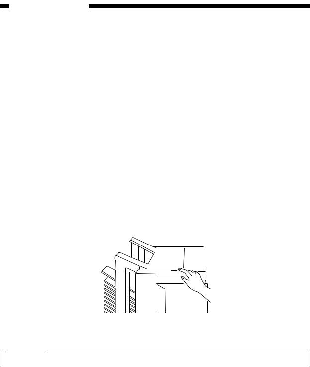
3. Manual insertion
Copies may be stapled by inserting them into the top bin and pressing the MANUAL STAPLE key.
1)Remove all copies from the bin unit.
•The bin unit returns to the home position.
2)Check that the bin unit is at the home position. n Otherwise, switch the copier OFF and then ON.
3)Insert the copies into the top bin of the bin unit along the guide plate.
•The MANUAL STAPLE key blinks.
n Make sure that no more than 50 copies (equivalent to paper of 80 g/m2) 4) Press the MANUAL STAPLE key.
Bring paper into contact
Figure 1-403
COPYRIGHT © 1997 CANON INC. |
CANON STAPLER SORTER-H1 REV.0 DEC. 1997 PRINTED IN JAPAN (IMPRIME AU JAPON) |
1–9 |
1. GENERAL DESCRIPTION
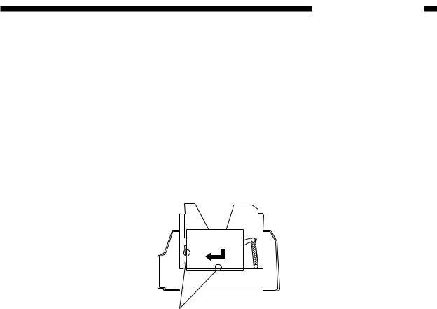
C.Resupply of staples to stapler
When staples in the staple cartridge have exhausted, the STAPLE RESUPPLY LED blinks. Then fill the stapler with new staples in the following procedure.
Caution:
Installing and removing the staple cartridge repeatedly may cause a staple jam. Therefore, advise customers not to remove the staple cartridge except when resupplying staples or at the time of staple jam.
1)Open the stapler unit cover.
2)Lift up the staple cartridge removal lever and remove the staple cartridge.
Figure 1-404
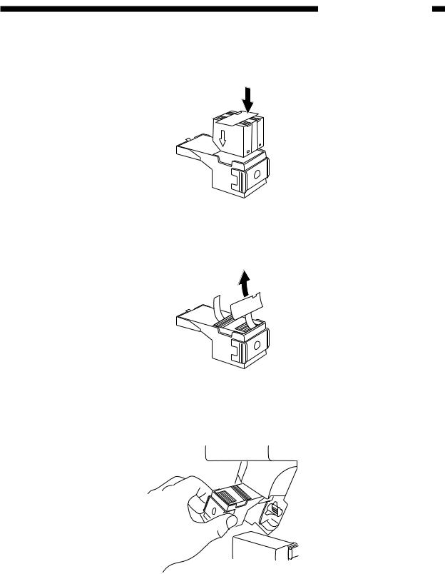
3) Remove the emptied staple case.
Figure 1-405
1–10 |
COPYRIGHT © 1997 CANON INC. |
CANON STAPLER SORTER-H1 REV.0 DEC. 1997 PRINTED IN JAPAN (IMPRIME AU JAPON) |
1. GENERAL DESCRIPTION
4) Set new staples correctly to the cartridge.
n Do not peel off the seal to which the staples are attached before setting the staples to the cartridge.
Figure 1-406
5) Pull out the seal attached with staples straight.
Figure 1-407
6) Set the staple cartridge.
Figure 1-408
7) Close the stapler unit cover.
Run the stapler unit idle until a staple comes out.
COPYRIGHT © 1997 CANON INC. |
CANON STAPLER SORTER-H1 REV.0 DEC. 1997 PRINTED IN JAPAN (IMPRIME AU JAPON) |
1–11 |
1. GENERAL DESCRIPTION
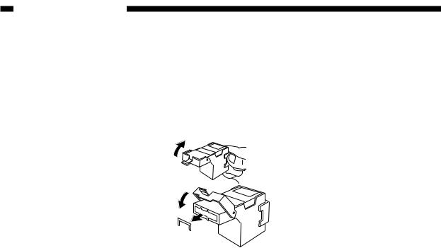
D. Removing a staple jam
When a staple jam occurs in the stapler, remove it in the following procedure:
1)Remove the staple cartridge.
2)Lower the face plate down to the floor and remove all jammed staples.
Figure 1-409
3) Close the face plate and set the staple cartridge.
1–12 |
COPYRIGHT © 1997 CANON INC. |
CANON STAPLER SORTER-H1 REV.0 DEC. 1997 PRINTED IN JAPAN (IMPRIME AU JAPON) |
1. GENERAL DESCRIPTION
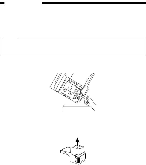
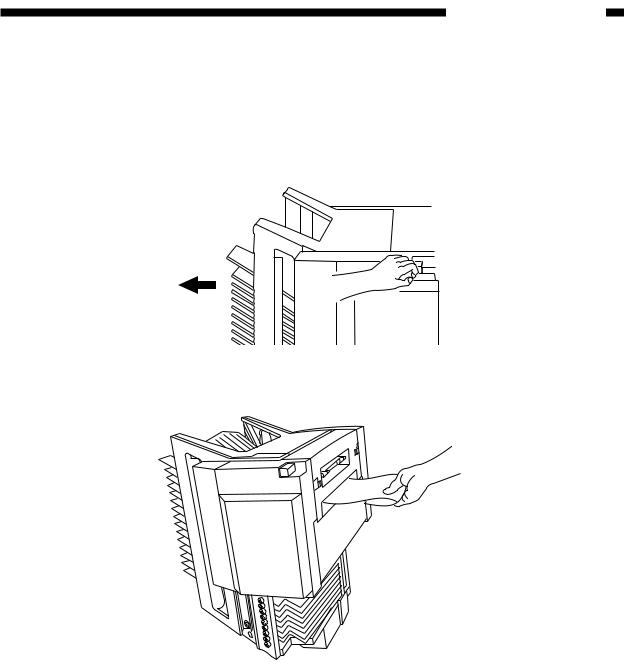
E. Removing paper clogging
1. Within sorter a. Feed unit
1) Press the latch lever to separate the sorter from the copier.
Figure 1-410
2) Remove the clogged paper.
Figure 1-411
3)When the paper can be seen from the bin side, insert your hand from the bin side and pull out the clogged paper.
4)Set the sorter to the copier.
COPYRIGHT © 1997 CANON INC. |
CANON STAPLER SORTER-H1 REV.0 DEC. 1997 PRINTED IN JAPAN (IMPRIME AU JAPON) |
1–13 |
1. GENERAL DESCRIPTION
1–14 |
COPYRIGHT © 1997 CANON INC. |
CANON STAPLER SORTER-H1 REV.0 DEC. 1997 PRINTED IN JAPAN (IMPRIME AU JAPON) |

CHAPTER 2
OPERATIONS AND TIMING
I. |
CONSTRUCTION.................................... |
2-1 |
IV. |
STAPLER UNIT DRIVE SYSTEM |
.........2-24 |
||
|
A. |
Functional Construction.................... |
2-1 |
|
A. |
Outline ............................................ |
2-24 |
|
B. |
Electrical Circuitry............................. |
2-2 |
|
B. |
Stapler Unit..................................... |
2-26 |
|
C. |
Sorter Controller Input/Output .......... |
2-3 |
|
C. |
Controlling the Swinging |
|
|
D. |
Communication between Copier |
|
|
|
Movement of the Stapler Unit......... |
2-32 |
|
|
and Sorter......................................... |
2-6 |
|
D. |
Holding the Paper........................... |
2-36 |
II. |
BASIC OPERATIONS.............................. |
2-7 |
|
E. |
Stapling Operation Timing.............. |
2-37 |
|
|
A. |
Outline .............................................. |
2-7 |
V. |
BIN UNIT DRIVE SYSTEM ................... |
2-38 |
|
|
B. |
Basic Operations .............................. |
2-9 |
|
A. |
Outline ............................................ |
2-38 |
III. |
FEED DRIVE SYSTEM ......................... |
2-16 |
|
B. |
Bin Unit........................................... |
2-39 |
|
|
A. |
Outline ............................................ |
2-16 |
|
C. Controlling the Guide Bar............... |
2-44 |
|
|
B. Controlling the Feed Speed............ |
2-18 |
|
D. Sensors Inside Bin Unit.................. |
2-47 |
||
|
C. |
Over Stack Condition ..................... |
2-19 |
|
E. |
Other Sensors ................................ |
2-48 |
|
D. |
Jam................................................. |
2-22 |
VI. |
POWER SUPPLY .................................. |
2-49 |
|
COPYRIGHT © 1997 CANON INC. |
CANON STAPLER SORTER-H1 REV.0 DEC. 1997 PRINTED IN JAPAN (IMPRIME AU JAPON) |
2. OPERATIONS AND TIMING
I. CONSTRUCTION
A. Functional construction
The sorter can be divided into six functional blocks; i.e., control panel, feed drive system, bin unit drive system, stapler unit drive system*, guide bar dive system, and control system.
|
Control |
|
|
|
panel |
|
|
|
|
Feed |
|
|
|
drive |
|
Bin unit |
system |
||
|
|
|
|
drive system |
|
|
system |
|
Stapler |
|
|
|
unit drive |
Control |
|
|
system |
|
|
|
|
|
|
Guide bar drive system
Figure 2-101
COPYRIGHT © 1997 CANON INC. |
CANON STAPLER SORTER-H1 REV.0 DEC. 1997 PRINTED IN JAPAN (IMPRIME AU JAPON) |
2–1 |
2. OPERATIONS AND TIMING
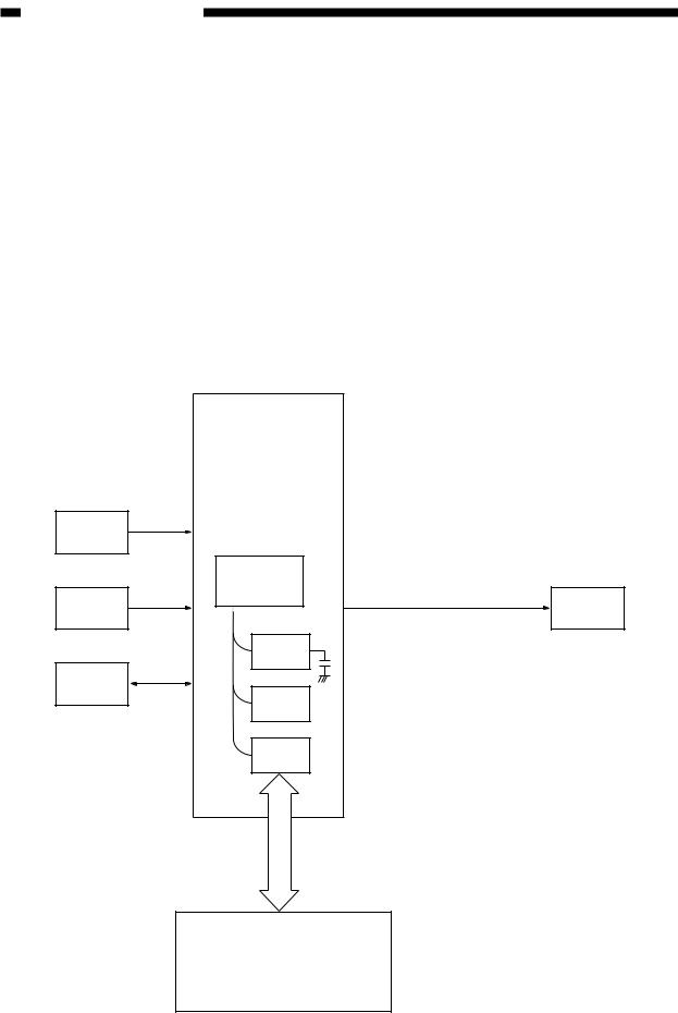
B. Electrical circuitry
The sorter is controlled by the sorter controller. The ICs on the sorter controller PCB has the functions as shown in the table below.
Symbol |
Function |
|
|
Q1 |
Sequence control |
|
|
Q2 |
Sensor value adjustment, operation mode control, etc. |
|
|
Q3 |
Built-in sequence program control |
|
|
Q4 |
Control of communication with copier |
|
|
|
Table 2-101 |
|
Sorter controller PCB |
Sensor |
|
|
Q1 CPU |
Switch |
Motor |
|
Q2 |
|
RAM |
Control |
|
panel |
Q3 |
|
|
|
ROM |
|
Q4 |
|
Communication |
|
IC |
|
Copier |
|
Figure 2-102 |
2–2 |
COPYRIGHT © 1997 CANON INC. |
CANON STAPLER SORTER-H1 REV.0 DEC. 1997 PRINTED IN JAPAN (IMPRIME AU JAPON) |
2. OPERATIONS AND TIMING
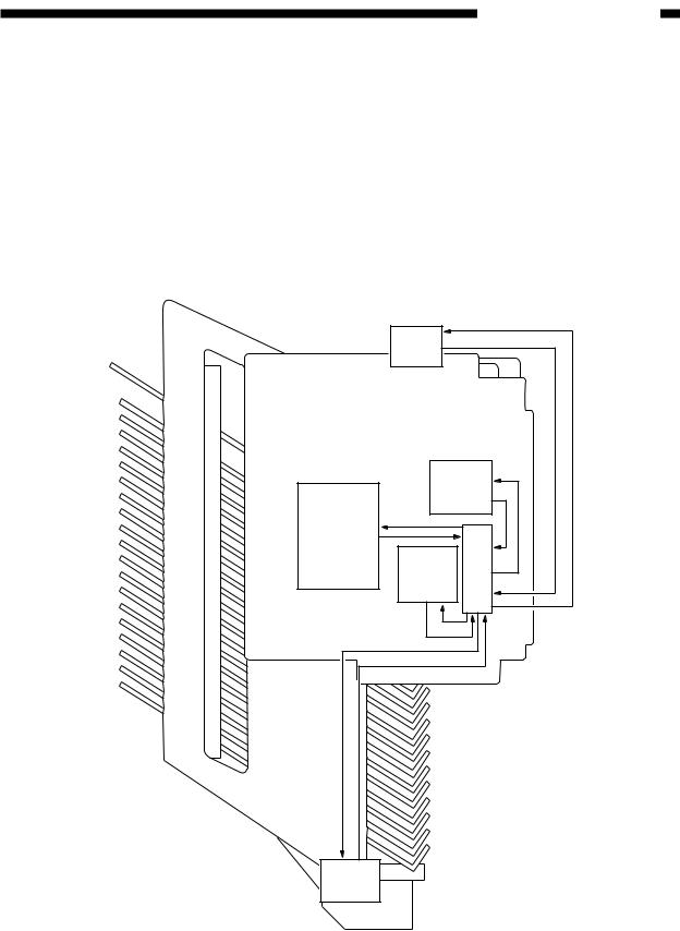
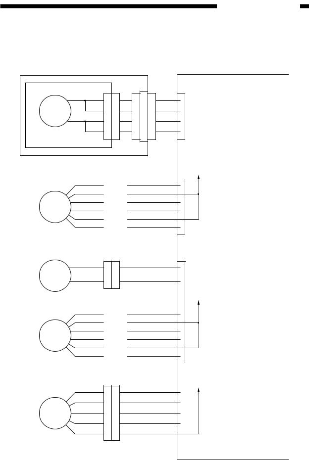
C. Sorter controller input/output
Sorter controller output
Stapler motor |
|
J201 |
|
|
|
1 |
1 11 |
|
|
M5 |
2 |
2 10 |
J102 |
|
|
|
|
||
|
3 |
3 |
9 |
|
|
4 |
4 |
8 |
|
Guide bar swing motor
M3
Shift motor
M1
Feed motor
M2
Stapler unit swing motor
M4
1
2
3
4
5
6
1
2
1
2
3
4
5
6
1
2
3
4
5
|
|
|
6 |
|
|
|
|
|
|
|
5 |
|
J110 |
|
4 |
|
|
3 |
|
|
|
|
2 |
|
|
|
1 |
|
|
|
|
|
|
|
|
J111
1
2
|
|
|
6 |
|
|
|
|
|
|
|
5 |
|
J112 |
|
4 |
|
|
3 |
|
|
|
|
2 |
|
|
|
1 |
|
|
|
|
|
|
|
|
J116
1
2
3
4
5
Sorter controller PCB
J7
11
22
33
44
|
J9 |
|
1 |
|
A |
2 |
|
|
3B
4A*
6 B*
J8
1
2
3 |
A |
4 |
|
5B
6A*
8 |
|
B* |
|
|
|
|
J12 |
|
5 |
|
A |
4 |
|
B |
3 |
|
A* |
2 |
|
B* |
1 |
|
|
|
|
|
See page 2-27 for details.
+24V
See page 2-46 for details.
See page 2-42 for details.
+24V
See page 2-17 for details.
+24V
See page 2-34 for details.
Figure 2-103
COPYRIGHT © 1997 CANON INC. |
CANON STAPLER SORTER-H1 REV.0 DEC. 1997 PRINTED IN JAPAN (IMPRIME AU JAPON) |
2–3 |

2. OPERATIONS AND TIMING
Sorter controller input (1/2)
|
|
|
|
|
|
|
Sorter controller PCB |
|
MS5 |
|
|
J201 |
|
|
|
J7 |
|
NO |
COM |
7 |
7 |
5 |
7 |
7 |
SPEMP |
When staple is |
|
|
|
|
|
|
|
||
|
|
|
|
|
|
|
|
absent, "1" |
No-staple detection |
|
|
|
|
|
|
|
|
MS6 |
|
|
|
|
|
|
|
|
NO |
COM |
8 |
8 |
4 |
8 |
8 |
SP CART |
When cartridge is |
|
|
|
|
|
|
|
||
|
|
|
|
|
J102 |
|
|
absent, "1" |
No-cartridge detection |
|
|
|
|
|
|
||
|
|
|
|
|
|
|
|
|
+5V |
|
|
|
|
|
|
|
|
PI8 |
|
9 |
9 |
3 |
9 |
9 |
SPLHP |
When stapling operation |
|
|
|
|
|
|
|||
|
|
|
|
|
|
|
is at home position, "0" |
|
|
|
|
|
|
|
|
|
|
Stapling |
|
|
|
|
|
|
|
|
operation home |
|
|
|
|
|
|
|
|
+5V position sensor |
|
|
|
|
|
|
|
|
PI9 |
|
11 |
11 |
1 |
11 |
11 |
SELF P When first staple is |
|
|
|
|
|
|
|
|||
|
|
|
|
|
|
|
reached, "0" |
|
Automatic |
|
|
|
|
|
|
||
|
|
|
|
|
|
|
||
first staple sensor |
|
|
|
|
|
+24V |
|
|
MS3 |
|
|
|
|
|
|
|
|
|
|
|
|
J103 |
|
|
|
|
|
|
|
|
|
|
|
|
|
NO |
COM |
|
|
1 |
1 |
12 |
|
|
|
|
|
|
2 |
2 |
13 |
IBUTU |
When obstacle is |
Obstacle detection |
|
|
|
|
|
|||
|
|
|
|
|
|
detected, "0" |
||
|
|
|
|
|
|
|
+5V |
|
Bin unit upper limit sensor |
|
|
|
|
J11 |
|
||
|
3 |
|
|
|
|
1 |
|
|
|
2 |
|
|
|
|
2 |
|
|
PI4 |
1 |
|
|
|
|
3 |
BUL |
When bin unit reaches |
|
|
|
|
|
|
|
|
the upper limit, "0" |
|
|
|
|
|
|
|
+5V |
|
Bin unit lower limit sensor |
|
|
|
|
|
|
||
|
3 |
|
|
|
|
4 |
|
|
|
2 |
|
|
|
|
5 |
|
|
PI5 |
1 |
|
|
|
|
6 |
BLL |
When bin unit reaches |
|
|
|
|
|
|
|
|
the lower limit, "0" |
|
|
|
|
|
|
|
+5V |
|
Joint sensor |
|
|
|
|
|
J13 |
|
|
|
3 |
|
|
|
|
1 |
|
|
|
2 |
|
|
|
|
2 |
|
|
PI6 |
1 |
|
|
|
|
3 |
SOP |
When sorter is |
|
|
|
|
|
|
|
|
connected with copier, |
Control panel |
J301 |
|
|
|
|
|
|
"1" |
|
J201 |
|
J104 |
|
|
|
||
|
|
|
|
|
|
|
||
|
3 |
3 |
2 |
2 |
3 |
3 |
SPL SW |
In manual stapling |
|
|
|
|
|
|
|
||
|
|
|
|
|
|
|
|
operation, "0" |
|
|
|
|
|
Figure 2-104 |
|
|
|
2–4 |
COPYRIGHT © 1997 CANON INC. |
CANON STAPLER SORTER-H1 REV.0 DEC. 1997 PRINTED IN JAPAN (IMPRIME AU JAPON) |
2. OPERATIONS AND TIMING
Sorter controller input (2/2)
|
Bin inside paper |
|
J203 |
||||||
|
|
|
sensor |
|
|||||
|
|
|
|
|
1 |
|
|
1 |
|
|
|
|
|
|
|
|
|||
|
|
|
|
2 |
|
|
2 |
||
|
S1 |
|
|
|
|
|
|
|
|
|
|
|
|
|
|
|
|
||
Light-emitting unit |
|
|
|
||||||
|
Bin-inside paper |
|
J204 |
||||||
|
|
|
sensor |
|
|||||
|
|
|
|
2 |
|
|
2 |
||
|
S2 |
|
1 |
|
|
1 |
|||
|
|
|
|
|
|
|
|
||
Light-receiving unit |
|
|
|
||||||
Guide bar home |
|
|
|
||||||
position sensor |
|
|
|
||||||
|
|
|
|
|
|
1 |
|
|
|
|
|
|
|
|
|
|
|
|
|
|
|
|
|
|
|
2 |
|
|
|
|
|
PI3 |
|
|
3 |
|
|
|
|
|
|
|
|
|
|
|
|
||
|
|
|
|
|
|
|
|
|
|
Joint switch
MS1
NO COM
Bin shift motor
clock sensor |
NO |
||||||
|
|
||||||
|
|
|
|
|
3 |
|
|
|
|
|
|
|
|
|
|
|
|
|
|
|
2 |
|
|
|
|
|
PI1 |
1 |
|
|
|
|
|
|
|
|
|
||
Lead cam home |
|
|
|||||
position sensor |
|
|
|||||
|
|
|
|
|
3 |
|
|
|
|
|
|
|
|
|
|
|
|
|
|
|
2 |
|
|
|
|
|
PI2 |
1 |
|
|
|
|
|
|
|
|
|
||
Stapler unit cover switch |
|
|
|||||
|
|
MS2 |
|
|
|
||
NO |
|
|
|
|
COM |
|
|
|
|
|
|
|
|
|
|
|
|
|
|
|
|
|
|
|
|
|
|
|
|
|
|
Stapler unit home position switch MS4
NO COM
Stapler unit cover sensor
|
|
|
|
|
|
3 |
|
|
|
|
|
|
|
|
2 |
|
|
|
|
PI7 |
1 |
|
|
|||
|
|
|
|
|
|
|
||
Control panel |
J301 |
|||||||
|
S3 |
|
|
|||||
|
|
|
|
|
|
|
1 |
|
|
|
|
|
|
|
|
2 |
|
|
|
|
|
|
|
|
4 |
|
|
|
|
|
|
|
|
|
|
|
|
|
|
|
|
|
|
|
|
|
|
|
|
|
|
|
|
|
|
|
|
|
Sorter controller PCB |
|||
|
|
|
|
|
|
|
|
|
|
|
|
|
|
|
|
+5V |
|
|||||||||
|
4 |
|
|
|
|
|
|
|
|
|
1 |
J4 |
|
|
|
|
|
|
||||||||
|
|
|
|
|
|
|
|
|
|
|
|
|||||||||||||||
|
|
|
|
|
|
|
1 |
|
|
|
|
|
|
|
|
|
|
|
|
|
|
|||||
|
3 |
|
|
|
|
|
|
2 |
|
|
2 |
|
|
|
|
|
|
|
BIN LED |
LED emitting light at "1" |
||||||
|
|
|
|
|
|
|
|
|
|
|
|
|
|
|
|
|
|
|
|
|
|
|||||
|
|
|
|
|
|
|
|
J108 |
|
|
|
|
|
|
|
|
|
|
|
|
|
|
|
|
|
(blinking) |
|
|
|
|
|
|
|
|
|
|
|
|
|
|
|
|
|
|
|
|
|
|
|
|
|
|
|
|
2 |
|
|
|
|
|
|
3 |
|
|
3 |
|
|
|
|
|
|
|
PA CHE |
When paper is present |
||||||
|
1 |
|
|
|
|
|
|
4 |
|
|
4 |
|
|
|
|
|
|
|
||||||||
|
|
|
|
|
|
|
|
|
|
|
|
|
|
|
|
|
|
|
|
in bin, "1" |
||||||
|
|
|
|
|
|
|
|
|
|
|
|
|
|
|
|
|
|
|
|
|
|
|
|
|
|
|
|
|
|
|
|
|
|
|
|
|
|
|
|
|
|
|
|
|
|
|
|
|
|
|
|
|
|
|
|
|
|
|
|
|
|
|
|
|
|
|
|
|
|
+5V |
|
|||||||||
|
|
|
|
|
|
|
|
|
|
|
|
|
|
|
|
|
||||||||||
|
|
|
|
|
|
|
|
|
|
|
|
|
|
6 |
|
|
|
|
|
|
|
|
|
STYGHP |
When guide bar is at |
|
|
|
|
|
|
|
|
|
|
|
|
|
|
|
|
|
|
|
|
|
|
|
|
||||
|
|
|
|
|
|
|
|
|
|
|
|
|
|
7 |
|
|
|
|
|
|
|
|
|
|||
|
|
|
|
|
|
|
|
|
|
|
|
|
|
|
|
|
|
|
|
|
|
|
|
|
|
|
|
|
|
|
|
|
|
|
|
|
|
|
|
|
8 |
|
|
|
|
|
|
|
|
|
|
|
the home position, "1" |
|
|
|
|
|
|
|
|
|
|
|
|
|
|
|
|
|
|
|
|
|
|
|
|
|
||
|
|
|
|
|
|
|
|
|
|
|
|
|
|
|
|
+24V |
|
|||||||||
|
|
|
|
|
|
|
|
|
|
|
|
|
|
|
|
|
||||||||||
|
|
|
|
|
|
|
|
|
|
|
|
|
|
1 |
J10 |
|
|
|
|
|
|
|
||||
|
|
|
|
|
|
|
|
|
|
|
|
|
|
|
|
|
||||||||||
|
|
|
|
|
|
|
|
|
|
|
|
|
|
|
|
|
|
|
|
|
|
|
|
|
|
|
|
|
|
|
|
|
|
|
|
|
|
|
|
|
2 |
|
|
|
|
|
|
|
JOI SW |
When sorter is connected |
|||
|
|
|
|
|
|
|
|
|
|
|
|
|
|
|
|
|
|
|
|
|
|
|||||
MS7 |
Obstacle |
|
|
+5V |
with copier, "1" |
|||||||||||||||||||||
|
|
|||||||||||||||||||||||||
|
|
|
COM |
|
|
detection |
|
|
|
|||||||||||||||||
|
|
|
|
|
|
|
|
|
|
|
|
|
|
1 |
J5 |
Pulses according to |
||||||||||
|
|
|
|
|
|
|
|
|
|
|
|
|
|
|
|
|
|
|
|
|
SHIFT CLK |
|||||
|
|
|
|
|
|
|
|
|
|
|
|
|
|
|
|
|
|
|
|
|
||||||
|
|
|
|
|
|
|
|
|
|
|
|
|
|
3 |
|
|
|
|
|
|
|
|||||
|
|
|
|
|
|
|
|
|
|
|
|
|
|
2 |
|
|
|
|
|
|
|
|
|
|
|
rotation speed of |
|
|
|
|
|
|
|
|
|
|
|
|
|
|
|
|
|
|
|
|
|
|
|
|
|
|
|
|
|
|
|
|
|
|
|
|
|
|
|
|
|
|
|
+5V |
shift motor |
|||||||||
|
|
|
|
|
|
|
|
|
|
|
|
|
|
|
|
|
||||||||||
|
|
|
|
|
|
|
|
|
|
|
|
|
|
4 |
|
|
|
|
|
|
|
|
|
|
|
|
|
|
|
|
|
|
|
|
|
|
|
|
|
|
|
|
|
|
|
|
|
|
|
|
|
|
|
|
|
|
|
|
|
|
|
|
|
|
|
|
|
6 |
|
|
|
|
|
|
|
|
|
|
|
|
|
|
|
|
|
|
|
|
|
|
|
|
|
|
5 |
|
|
|
|
|
|
|
|
|
CUMH |
When lead cam is at |
|
|
|
|
|
|
|
|
|
|
|
|
|
|
|
|
|
|
|
|
|
|
|
|
|
|||
|
|
|
|
|
|
|
|
|
|
|
|
|
|
|
|
|
|
|
|
|
|
|
|
|
|
the home position, "1" |
|
|
|
|
|
J115 |
|
|
|
|
|
|
+24V |
||||||||||||||
|
|
|
|
|
|
|
|
|
|
|
||||||||||||||||
|
|
|
|
|
|
|
|
|
|
|
|
|||||||||||||||
|
1 |
|
|
|
|
1 |
J6 |
|
|
|
|
|
|
|
|
|||||||||||
|
|
|
|
|
1 |
|
|
|
|
|
|
|
|
|
|
|
||||||||||
|
|
|
|
|
|
|
|
|
|
|
|
|
|
|
|
|
|
|
|
|
||||||
|
2 |
|
|
|
|
2 |
|
|
|
|
2 |
|
|
|
|
|
|
|
SPLOPN |
When stapler unit cover |
||||||
|
|
|
|
|
|
|
|
|
|
|
|
|
|
|
|
|
|
|
|
|
|
|||||
|
|
|
|
|
|
|
|
|
|
|
|
|
|
|
|
+24V |
is closed, "1" |
|||||||||
|
|
|
|
|
|
|
|
|
|
|
|
|
|
|
|
|
||||||||||
|
3 |
|
|
|
|
3 |
|
|
|
|
3 |
|
|
|
|
|
|
|
|
|
|
|
|
|||
|
|
|
|
|
|
|
|
|
|
|
|
|
|
|
|
|
|
|
|
|
||||||
|
4 |
|
|
|
|
4 |
|
|
|
|
4 |
|
|
|
|
|
|
|
SPUHP |
When stapler unit |
||||||
|
|
|
|
|
|
|
|
|
|
|
|
|
|
|
|
|
|
|
|
|
|
|||||
|
|
|
|
|
|
|
|
|
|
|
|
|
|
|
|
+5V |
is swinging home |
|||||||||
|
|
|
|
|
|
|
|
|
|
|
|
|
|
|
|
|||||||||||
|
|
|
|
|
|
|
|
|
|
|
|
|
|
|
|
position, "1" |
||||||||||
|
|
|
|
|
|
|
|
|
|
|
|
|
|
|
J14 |
|||||||||||
|
|
|
|
|
|
|
|
|
5 |
|
|
|
|
3 |
|
|||||||||||
|
5 |
|
|
|
|
|
|
|
|
|
|
|
|
|
|
|
|
|
|
|
|
|||||
|
6 |
|
|
|
|
6 |
|
|
|
|
2 |
|
|
|
|
|
|
|
|
|
|
|
|
|||
|
7 |
|
|
|
|
7 |
|
|
|
|
1 |
|
|
|
|
|
|
|
|
|
SPL COV |
When stapler unit |
||||
|
|
|
|
|
|
|
|
|
|
|
|
|
|
|
|
|
|
|
|
|
|
|
|
|||
|
|
|
|
|
|
|
|
|
|
|
|
|
|
|
|
|
|
|
|
|
|
|
|
|
|
cover is closed, "1" |
|
|
|
|
|
|
|
|
|
|
|
|
|
|
|
|
|
|
|
|
|
|
|
|
|
|
|
|
J202 |
|
|
J104 |
|
J3 |
|
|||||||||||||||||||
1 |
|
|
|
|
|
4 |
1 |
|
|
4 |
1 |
|
|
|
|
|
|
|
SPLED |
When stapling is |
||||||
2 |
|
|
|
|
|
3 |
2 |
|
|
3 |
2 |
|
|
|
|
|
|
|
HARI LED |
possible, "1"; |
||||||
4 |
|
|
|
|
|
1 |
4 |
|
|
|
1 |
4 |
|
|
|
|
|
|
|
|||||||
|
|
|
|
|
|
|
|
|
|
|
|
|
|
|
|
|
|
|
|
|
|
|
|
|
|
when staple is absent, "1" |
|
|
|
|
|
|
|
|
|
|
|
|
|
|
|
|
|
|
|
|
|
|
|
|
|
|
|
S4
Figure 2-105
COPYRIGHT © 1997 CANON INC. |
CANON STAPLER SORTER-H1 REV.0 DEC. 1997 PRINTED IN JAPAN (IMPRIME AU JAPON) |
2–5 |

2. OPERATIONS AND TIMING
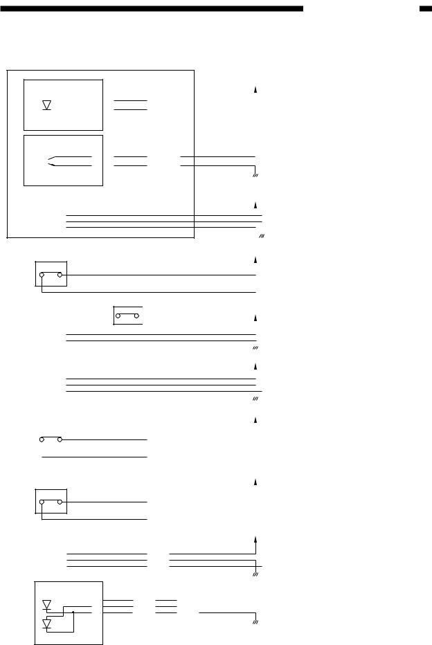
D.Communication between copier and sorter
1. Outline
The copier and sorter send status signals back and forth between them through the IPC (IC for communication) communication.
The sorter is provided with both the new and former IPC communication functions, which can be switched over according to the copier to be installed. The functions are changed over by turning ON or OFF the No. 6 dip switch (SW1) on the sorter controller PCB.
SW1-6 |
ON |
OFF |
|
|
|
Communication system |
Former IPC communication |
New IPC communication |
|
|
|
These signals are first written into the RAM on the sorter controller PCB and then sent out in response to control signals from the CPU (Q1).
Though a service man cannot check if status signals are properly transferred or not, if signals are improperly transferred, the automatic diagnosis function of the copier is activated and an error code is displayed on the control panel of the copier.
2–6 |
COPYRIGHT © 1997 CANON INC. |
CANON STAPLER SORTER-H1 REV.0 DEC. 1997 PRINTED IN JAPAN (IMPRIME AU JAPON) |

2. OPERATIONS AND TIMING
II. BASIC OPERATIONS
A. Outline
The sorter sorts and staples copies delivered to it according to the modes selected on the copier. The delivered copies can be also stapled by operating the operation keys on the copier.
Four operating modes as shown below are available.
1.Non sort mode
2.Sort mode
3.Group mode
4.Staple sort mode
1.Non sort mode
The sorter has a cascade stack function. When the number of copies is below 100, all of them are loaded into the first bin but, when exceeding 100, 30 or 25 copies are loaded into each bin depending on the paper size. When the 20th bin is loaded with copies, the sorter and copier stop operation. By removing all copies from the bins and turning ON the COPY START key, copying for the remaining paper is started.
( Whether the number of copies exceeding the maximum loading value of the sorter can be designated or not, number of copies stopping the operation, and the method of resuming the operation vary depending on the specifications of the copier.)
COPYRIGHT © 1997 CANON INC. |
CANON STAPLER SORTER-H1 REV.0 DEC. 1997 PRINTED IN JAPAN (IMPRIME AU JAPON) |
2–7 |
2. OPERATIONS AND TIMING
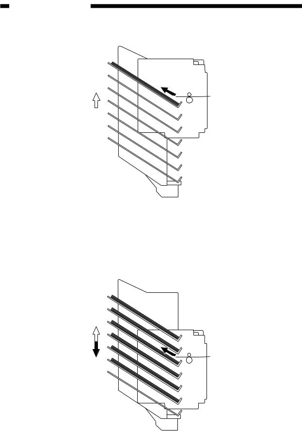
Figure 2-201
2. Sort/group/staple sort mode
The copies are delivered to the sort bins.
At this time, the bin units move up and down to sort the copies. When the copies are stapled, copies delivered into bins are stapled.
Figure 2-202
2–8 |
COPYRIGHT © 1997 CANON INC. |
CANON STAPLER SORTER-H1 REV.0 DEC. 1997 PRINTED IN JAPAN (IMPRIME AU JAPON) |
Loading...