


 Loading...
Service Manual
MF3110 Series
LaserBase MF3110
Aug 27 2004
Application
This manual has been issued by Canon Inc. for qualified persons to learn technical theory, installation, maintenance, and repair of products. This manual covers all localities where the products are sold. For this reason, there may be informa tion in this manual that does not apply to your locality.
Corrections
This manual may contain technical inaccuracies or typographical errors due to improvements or changes in products. When changes occur in applicable products or in the contents of this manual, Canon will release technical information as the need arises. In the event of major changes in the contents of this manual over a long or short period, Canon will issue a new edition of this manual.
The following paragraph does not apply to any countries where such provisions are inconsistent with local law.
Trademarks
The product names and company names used in this manual are the registered trademarks of the individual companies.
Copyright
This manual is copyrighted with all rights reserved. Under the copyright laws, this manual may not be copied, repro duced or translated into another language, in whole or in part, without the written consent of Canon Inc.
COPYRIGHT © 2001 CANON INC.
Printed in Japan
Caution
Use of this manual should be strictly supervised to avoid disclosure of confidential information.
Introduction
Symbols Used
This documentation uses the following symbols to indicate special information:
Symbol Description
Indicates an item of a non specific nature, possibly classified as Note, Caution, or Warning.
Indicates an item requiring care to avoid electric shocks.
Indicates an item requiring care to avoid combustion (fire).
Indicates an item prohibiting disassembly to avoid electric shocks or problems.
Indicates an item requiring disconnection of the power plug from the electric outlet.
Indicates an item intended to provide notes assisting the understanding of the topic in question.
Memo
Indicates an item of reference assisting the understanding of the topic in question.
REF.
Provides a description of a service mode.
Provides a description of the nature of an error indication.

Introduction
The following rules apply throughout this Service Manual:
1.Each chapter contains sections explaining the purpose of specific functions and the relationship between electrical and mechanical systems with reference to the timing of operation.
In the diagrams,  represents the path of mechanical drive; where a signal name accompanies the symbol , the arrow
  indicates the direction of the electric signal.
The expression "turn on the power" means flipping on the power switch, closing the front door, and closing the delivery unit door, which results in supplying the machine with power.
2.In the digital circuits, '1'is used to indicate that the voltage level of a given signal is "High", while '0' is used to indicate "Low".(The voltage value, however, differs from circuit to circuit.) In addition, the asterisk (*) as in "DRMD*" indicates that the DRMD signal goes on when '0'.
In practically all cases, the internal mechanisms of a microprocessor cannot be checked in the field. Therefore, the operations of the microprocessors used in the machines are not discussed: they are explained in terms of from sen sors to the input of the DC controller PCB and from the output of the DC controller PCB to the loads.
The descriptions in this Service Manual are subject to change without notice for product improvement or other pur poses, and major changes will be communicated in the form of Service Information bulletins.
All service persons are expected to have a good understanding of the contents of this Service Manual and all relevant Service Information bulletins and be able to identify and isolate faults in the machine."

Chapter 1 PRODUCT DESCRIPTION |
|
1.1 Product Specifications....................................................................................................................................... |
1 1 |
1.1.1Product Specifications................................................................................................................................. |
1 1 |
1.2 Detailed Specifications...................................................................................................................................... |
1 3 |
1.2.1Printing Speed ............................................................................................................................................. |
1 3 |
1.2.2Stack Upon Delivery................................................................................................................................... |
1 3 |
1.2.3System Requirements for Printer Driver..................................................................................................... |
1 4 |
1.3 Names of Parts................................................................................................................................................... |
1 5 |
1.3.1External View.............................................................................................................................................. |
1 5 |
1.3.2Operation panel ........................................................................................................................................... |
1 7 |
1.4 Safety................................................................................................................................................................. |
1 8 |
1.4.1Safety of Laser Light................................................................................................................................... |
1 8 |
1.4.2Handling the Laser Unit .............................................................................................................................. |
1 8 |
1.4.3Safety of Toner............................................................................................................................................ |
1 9 |
Chapter 2 TECHNICAL REFERENCE
2.1 |
Document Feed and Exposure System |
.............................................................................................................. 2 1 |
2.1.1 Overview/Configuration ............................................................................................................................. |
2 1 |
|
2.2 |
Laser Exposure.................................................................................................................................................. |
2 2 |
2.2.1 Overview/Configuration ............................................................................................................................. |
2 2 |
|
2.3 |
Image Formation ............................................................................................................................................... |
2 4 |
2.3.1 Overview/Configuration ............................................................................................................................. |
2 4 |
|
2.4 |
Pickup and Feed System.................................................................................................................................... |
2 6 |
2.4.1 Overview/Configuration ............................................................................................................................. |
2 6 |
|
2.4.2 Detection Jams............................................................................................................................................ |
2 7 |
|
2.5 |
Fixing Unit ........................................................................................................................................................ |
2 9 |
2.5.1 Overview/Configuration ............................................................................................................................. |
2 9 |
|
2.5.2 Protective Function................................................................................................................................... |
2 10 |
|
2.6 |
External and Controls...................................................................................................................................... |
2 12 |
2.6.1 Power Supply............................................................................................................................................ |
2 12 |
|
Chapter 3 DISASSEMBLY AND ASSEMBLY
3.1 EXTERNAL AND CONTROLS SYSTEM ..................................................................................................... |
3 1 |
3.1.1 Front Cover................................................................................................................................................. |
3 1 |
3.1.2 Rear Cover .................................................................................................................................................. |
3 1 |
3.1.3 Top Cover ................................................................................................................................................... |
3 2 |
3.1.4 Right Cover................................................................................................................................................. |
3 4 |
3.1.5 Left Cover................................................................................................................................................... |
3 4 |
3.1.6 Operation Panel Unit................................................................................................................................... |
3 5 |
3.1.7 SCNT Board................................................................................................................................................ |
3 7 |
3.1.8 ECNT Board ............................................................................................................................................... |
3 9 |

3.1.9 Power Supply PCB.................................................................................................................................... |
3 10 |
3.1.10 High voitage Power Supply PCB............................................................................................................ |
3 12 |
3.1.11 Top Sensor............................................................................................................................................... |
3 14 |
3.1.12 Paper Delivery Sensor............................................................................................................................. |
3 17 |
3.2 Document Feed/Exposure System................................................................................................................... |
3 21 |
3.2.1 Scanner Unit.............................................................................................................................................. |
3 21 |
3.2.2 Scanner Cover Unit................................................................................................................................... |
3 22 |
3.2.3 CCD Unit................................................................................................................................................... |
3 25 |
3.2.4 Flatbed Motor Unit.................................................................................................................................... |
3 28 |
3.3 LASER EXPOSURE SYSTEM ...................................................................................................................... |
3 31 |
3.3.1 Laser/Scanner Unit.................................................................................................................................... |
3 31 |
3.4 IMAGE FORMATION SYSTEM................................................................................................................... |
3 34 |
3.4.1 Transfer Charging Roller .......................................................................................................................... |
3 34 |
3.5 PICKUP AND FEEDING SYSTEM............................................................................................................... |
3 35 |
3.5.1 Cassette Pickup Roller .............................................................................................................................. |
3 35 |
3.5.2 Cassette Pickup Solenoid .......................................................................................................................... |
3 39 |
3.5.3 Cassette Separation Pad ............................................................................................................................ |
3 42 |
3.5.4 Paper Feed Roller...................................................................................................................................... |
3 43 |
3.5.5 Manual Pickup Solenoid ........................................................................................................................... |
3 48 |
3.5.6 Main Motor ............................................................................................................................................... |
3 51 |
3.5.7 Gear Unit................................................................................................................................................... |
3 55 |
3.6 FIXING SYSTEM........................................................................................................................................... |
3 56 |
Chapter 4 MAINTENANCE AND INSPECTION
4.1 Periodically Replaced Parts............................................................................................................................... |
4 1 |
4.1.1Parts Requiring Periodical Replacement ..................................................................................................... |
4 1 |
4.2 Consumables...................................................................................................................................................... |
4 2 |
4.2.1Consumable ................................................................................................................................................. |
4 2 |
4.3 Periodical Service.............................................................................................................................................. |
4 3 |
4.3.1Items Requiring Scheduled Servicing ......................................................................................................... |
4 3 |
4.4 Cleaning............................................................................................................................................................. |
4 4 |
4.4.1Items Requiring Cleaning............................................................................................................................ |
4 4 |
4.4.2Cleaning Method (external covers) ............................................................................................................. |
4 5 |
4.4.3Cleaning Method (scanning unit) ................................................................................................................ |
4 5 |
4.4.4Cleaning Method (printer unit).................................................................................................................... |
4 6 |
4.5 Lubrications....................................................................................................................................................... |
4 8 |
4.5.1Areas Requiring Application of Grease....................................................................................................... |
4 8 |
4.5.2Delivery Idler Gear...................................................................................................................................... |
4 9 |
4.5.3Fixing Drive Transmission Gear ............................................................................................................... |
4 10 |
4.5.4Large Gear Bushing R ............................................................................................................................... |
4 10 |
4.5.5Large Gear ................................................................................................................................................. |
4 11 |
4.5.6Feed Gear................................................................................................................................................... |
4 11 |
4.5.7Internal Gear.............................................................................................................................................. |
4 12 |
4.5.8Large Gear Deceleration Gear/Plate R ...................................................................................................... |
4 12 |
4.5.9Main Motor................................................................................................................................................ |
4 13 |
4.5.10Drive Releasing Arm............................................................................................................................... |
4 14 |
4.5.11FU Delivery Roller.................................................................................................................................. |
4 14 |
4.5.12Pickup Idler Gear..................................................................................................................................... |
4 15 |
|
|
|
|
|
|
4.5.13Feed Deceleration Gear........................................................................................................................... |
4 15 |
4.5.14Fixing Deceleration Gear ........................................................................................................................ |
4 16 |
4.5.15FD Delivery Roller.................................................................................................................................. |
4 17 |
4.5.16Large Gear Bushing F ............................................................................................................................. |
4 17 |
4.5.17Pressure roller.......................................................................................................................................... |
4 18 |
4.5.18Cassette Pickup Roller............................................................................................................................. |
4 18 |
4.5.19CCD Shaft ............................................................................................................................................... |
4 19 |
4.5.20Wheel Shaft............................................................................................................................................. |
4 19 |
Chapter 5 TROUBLE SHOOTING
5.1 |
Phenomenon Table............................................................................................................................................ |
5 1 |
5.1.1Symptoms.................................................................................................................................................... |
5 1 |
|
5.2 |
Countermeasure................................................................................................................................................. |
5 2 |
5.2.1 Image Faults................................................................................................................................................ |
5 2 |
|
5.2.2 Malfunction................................................................................................................................................. |
5 2 |
|
5.2.3 Printing/Scanning........................................................................................................................................ |
5 3 |
|
5.2.4 Jam (Main Unit).......................................................................................................................................... |
5 3 |
|
5.3 |
Measurement and Adjustment........................................................................................................................... |
5 4 |
5.3.1 Basic Adjustments ...................................................................................................................................... |
5 4 |
|
5.4 |
Service Tools..................................................................................................................................................... |
5 5 |
5.4.1Special Tools............................................................................................................................................... |
5 5 |
|
5.5 |
Error Code......................................................................................................................................................... |
5 6 |
5.5.1 Outline......................................................................................................................................................... |
5 6 |
|
5.5.2 Service Error Code...................................................................................................................................... |
5 6 |
|
5.6 |
Service Mode..................................................................................................................................................... |
5 8 |
5.6.1 Outline......................................................................................................................................................... |
5 8 |
|
5.6.2 Service Soft Switch Settings (SSSW)....................................................................................................... |
5 12 |
|
5.6.3 ROM Management (ROM)....................................................................................................................... |
5 14 |
|
5.6.4 Test Mode (TEST).................................................................................................................................... |
5 14 |
|
Chapter 6 APPENDIX
6.1 Outline of Electrical Components..................................................................................................................... |
6 1 |
6.1.1 Sensor.......................................................................................................................................................... |
6 1 |
6.1.2 PCBs ........................................................................................................................................................... |
6 2 |
Chapter 1 PRODUCT
DESCRIPTION

Contents
1.1 |
Product Specifications....................................................................................................................................... |
1 1 |
1.1.1Product Specifications................................................................................................................................. |
1 1 |
|
1.2 |
Detailed Specifications...................................................................................................................................... |
1 3 |
1.2.1Printing Speed ............................................................................................................................................. |
1 3 |
|
1.2.2Stack Upon Delivery................................................................................................................................... |
1 3 |
|
1.2.3System Requirements for Printer Driver..................................................................................................... |
1 4 |
|
1.3 |
Names of Parts................................................................................................................................................... |
1 5 |
1.3.1External View.............................................................................................................................................. |
1 5 |
|
1.3.2Operation panel ........................................................................................................................................... |
1 7 |
|
1.4 |
Safety................................................................................................................................................................. |
1 8 |
1.4.1Safety of Laser Light................................................................................................................................... |
1 8 |
|
1.4.2Handling the Laser Unit .............................................................................................................................. |
1 8 |
|
1.4.3Safety of Toner............................................................................................................................................ |
1 9 |
|

Chapter 1
1.1 Product Specifications
1.1.1 Product Specifications |
0007-7055 |
Body installation method |
Desktop |
|
|
Exposure Method |
Semi conductor laser |
|
|
Development Method |
Toner projection |
|
|
Transfer Method |
Roller transfer |
|
|
Fixing method |
On demand fixing |
|
|
Delivery method |
Facedown /Faceup |
|
|
Toner level detection function |
None |
|
|
Toner supply type |
Toner cartridge replacement / Cartridge EP 27 |
|
|
Document type |
Sheet, 3D object (up to 2kg) |
|
|
Maximum document size |
216 x 297 mm |
|
|
Scanning method |
CCD scanning method |
|
|
Reproduction ratio |
1:1+/ 1.0 %, 1:2.000, 1:1.294, 1:0.786, 1:0.647, 1:0.500 / Zoom: |
|
0.500 to 2.000 (unit: 1 %) |
|
|
Print area |
Print: 5 mm and more inner from paper egdes/ Copy: 2 mm and more |
|
inner from paper egdes |
|
|
Reading resolution |
1200 x 2400 dpi |
|
|
Copying resolution |
600 x 600 dpi |
|
|
Printing resolution |
1200 x 600 dpi |
|
|
Print speed (A4) |
approx. 20 sheets/min |
|
|
Print speed(LTR) |
approx. 21 sheets/min |
|
|
Warm up Time |
Approx. 260 sec. (temperature: 20 deg C, humidty: 65%; from when |
|
the machine is plugged in untill the standby display appears) : Warm |
|
up time may differ depending on the condition and environment of |
|
the machine. |
|
|
First Print Time |
approx. 13.8 sec. |
|
|
Cassette paper size |
A4, B5, A5, Letter, Legal, Executive |
|
|
Multi purpose paper size |
A4, B5, A5, Letter, Legal, Executive, Envelope (DL, ISO C5, |
|
COM10, MONARCH) |
|
|
1-1

Chapter 1 Running H/F 5
Cassette paper type |
Plain paper (64 to 90 g/m2), Heavy paper (91 to 128 g/m2), |
|
Transparency |
|
|
Multi purpose paper type |
Plain paper (64 to 90 g/m2), Heavy paper (91 to 163 g/m2), |
|
Transparency, Envelope (DL, ISO C5, COM10, MONARCH) |
|
|
Cassette capacity |
Plain paper (64, 75, 80 g/m2): approx. 250 sheets, Heavy paper (90, |
|
105 g/m2): approx. 200 sheets, Heavy paper H (128 g/m2): approx. |
|
100 sheets, Transparency: approx. 100 sheets, Envelope: approx. 20 |
|
sheets |
|
|
Multi purpose capacity |
1 sheet |
|
|
Continuous reproduction |
99 sheets |
|
|
Energy save mode |
Yes |
|
|
Operating environment |
15 to 32.5 deg C |
(Temperature range) |
|
|
|
Operating environment |
20 to 80 %RH |
(Humidity range) |
|
|
|
Power supply rating |
200 240V, 50 60Hz |
|
|
Power consumption |
approx. 700 W |
(Maximum) |
|
|
|
Dimensions |
449 mm x 462 mm x 369 mm |
|
|
Weight |
approx. 12 kg (including cartridge) |
|
|
Option |
None |
|
|
1-2

Chapter 1
1.2 Detailed Specifications
1.2.1 Printing Speed
0007-7946
T-1-1
|
|
|
Fixing mode |
|
|
|
|
|
|
|
|
|
|
|
|
|
|
|
|
|
|
|
|
|
|
|
|
|
|
|
|
Paper size |
Plain |
Plain |
Heavy |
|
Heavy |
Transpa |
Envelope |
COM10 |
|
|||
|
|
|
paper |
paper L |
paper |
|
paper H |
rency |
|
|
|
|
|
|
|
|
|
|
|
|
|
|
|
|
|
|
|
|
|
|
|
A4 ( to 64 g/m2) |
20 |
20 |
20 |
|
12 |
20 |
|
|
|
|
||
|
|
|
|
|
|
|
|
|
|
|
|
|
|
|
|
|
A4 (65 to 90 g/m2) |
|
18 |
10 |
|
8 |
18 |
|
|
|
|
||
|
|
|
|
|
|
|
|
|
|
|
|
|
|
|
|
|
B5 (64 to 90 g/m2) |
8 |
8 |
4 |
|
4 |
8 |
|
|
|
|
||
|
|
|
|
|
|
|
|
|
|
|
|
|
|
|
|
|
A5 (64 to 90 g/m2) |
8 |
8 |
4 |
|
4 |
8 |
|
|
|
|
||
|
|
|
|
|
|
|
|
|
|
|
|
|
|
|
|
|
A4 (105 to 128 g/m2) |
|
|
18 |
|
12 |
|
|
|
|
|
||
|
|
|
|
|
|
|
|
|
|
|
|
|
|
|
|
|
B5 (105 to 128 g/m2) |
|
|
4 |
|
4 |
|
|
|
|
|
||
|
|
|
|
|
|
|
|
|
|
|
|
|
|
|
|
|
LTR (75 to 90 g/m2) |
21 |
21 |
21 |
|
12 |
21 |
|
|
|
|
||
|
|
|
|
|
|
|
|
|
|
|
|
|
|
|
|
|
LGL (75 to 90 g/m2) |
15 |
|
|
|
|
|
|
|
|
|
||
|
|
|
|
|
|
|
|
|
|
|
|
|
|
|
|
|
LTR (Bond 75 to 90 g/m2, |
|
|
21 |
|
12 |
|
|
|
|
|
||
|
|
105 g/m2) |
|
|
|
|||||||||
|
|
|
|
|
|
|
|
|
|
|
|
|
|
|
|
|
|
|
|
|
|
|
|
|
|
|
|
|
|
|
|
Envelope |
|
|
|
|
|
|
4 |
4 |
|
|
||
|
|
|
|
|
|
|
|
|
|
|
|
|
|
|
(unit: sheets/min) |
|
|
|
|
|
|
|
|
|
|
|
|
||
1.2.2 Stack Upon Delivery |
|
|
|
|
|
|
|
|
0007-6394 |
|||||
|
|
|
|
|
T-1-2 |
|
|
|
|
|
|
|
|
|
|
|
|
|
|
|
|
|
|
|
|
||||
|
|
Paper type |
|
|
|
|
Face down |
|
Face up |
|
|
|||
|
|
|
|
|
|
|
|
|
|
|||||
|
|
Plain paper (64 to 75 g/m2) |
|
|
|
Approx. 60 sheets |
|
1 sheet |
|
|
||||
|
|
|
|
|
|
|
|
|
|
|||||
|
|
Heavy paper (91 to 128 g/m2) |
|
|
|
Approx. 30 sheets |
|
1 sheet |
|
|
||||
|
|
|
|
|
|
|
|
|
|
|
||||
|
|
Transparency |
|
|
|
|
Approx. 10 sheets |
|
1 sheet |
|
|
|||
|
|
|
|
|
|
|
|
|
|
|
|
|||
|
|
Label |
|
|
|
|
|
|
|
1 sheet |
|
|
||
|
|
|
|
|
|
|
|
|
|
|
||||
|
|
Envelope |
|
|
|
|
Approx. 10 sheets |
|
1 sheet |
|
|
|||
|
|
|
|
|
|
|
|
|
|
|
|
|
|
|
|
|
|
|
|
|
|
|
|
|
|
|
|
|
|
1-3

Chapter 1 Running H/F 5
 The values herein are estimates only and are subject to change for product improvement.
1.2.3 System Requirements for Printer Driver |
0007-8001 |
Operating System
Windows 98, Windows Me, Windows 2000 Professional, Windows XP
Computer
Any computer on whitch Windows 98, Windows Me, Windows 2000, or Windows XP runs properly.
Hardware Environment
IBM or IBM compatible PC
CD ROM drive or network environment with the access to CD ROMPC equipped with a USB port and the USB class driver installed
T-1-3
OS |
CPU |
RAM |
Available Free Disk Space |
|
|
|
|
|
|
|
Intel Pentium 90 MHz or |
32 MB of RAM, 64 |
At least 115 MB, 200MB or greater is |
|
Windows 98 |
MB or greater is |
|||
greater |
recommended |
|||
|
recommended |
|||
|
|
|
||
|
|
|
|
|
|
Intel Pentium 150 MHz or |
32 MB of RAM, 64 |
At least 115 MB, 200MB or greater is |
|
Windows Me |
MB or greater is |
|||
greater |
recommended |
|||
|
recommended |
|||
|
|
|
||
|
|
|
|
|
|
Intel Pentium 133 MHz or |
64 MB of RAM, 128 |
|
|
Windows 2000* |
greater, or compatible micro |
At least 115 MB, 200MB or greater is |
||
MB or greater is |
||||
Professional |
processors (up to 2 |
recommended |
||
recommended |
||||
|
processors are supported) |
|
||
|
|
|
||
|
|
|
|
|
|
PentiumFamily300MHzor |
64 MB of RAM, 128 |
At least 115 MB, 200MB or greater is |
|
Windows XP* |
MB or greater is |
|||
greater |
recommended |
|||
|
recommended |
|||
|
|
|
||
|
|
|
|
*Log on as a user with adoministrator privileges is recommended.
1-4

|
Chapter 1 |
|
|
1.3 Names of Parts |
|
|
|
1.3.1 External View |
0007-6429 |
<Front View> |
|
[1]
[2]
[3]
[4]
[5]
[6]
[7]
F-1-1
|
T-1-4 |
[1] Platen glass cover |
[5] Front cover |
[2] Platen glass |
[6] Multi purpose feeder |
[3] Operation panel |
[7] Cassette |
[4] Output tray |
|
1-5
Chapter 1 Running H/F 5
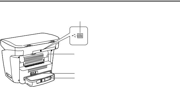
<Rear View>
[1]
[2]
[3]
[4]
F-1-2
T-1-5
[1] USB port
[2] Face up cover
[3] Power socket
[4] Extension cover
1-6
|
|
|
Chapter 1 |
1.3.2 Operation panel |
|
0007-6441 |
|
[1] [2] |
[3] [4] [5] [6] |
[7] |
[8] [9] [10] |
|
1 |
2 |
3 |
|
4 |
5 |
6 |
|
7 |
8 |
9 |
|
|
0 |
|
|
[11] [12][13][14] [15][16] [17] |
|
|
F-1-3 |
|
|
|
|
|
|
T-1-6 |
[1] COPY key |
|
[10] Energy Saver key |
|
[2] SCAN key |
|
[11] Collate/2on1 key |
|
[3] Enlarge/Reduce key |
|
[12] Image Quality key |
|
[4] Exposure key |
|
[13] Memory indicator |
|
[5] Alarm indicator |
|
[14] Menu key |
|
[6] LCD |
|
|
[15] Cursor keys |
[7] Numeric keys |
|
[16] OK key |
|
[8] Start key |
|
[17] Status Monitor key |
|
[9] Stop/Reset key |
|
|
|
1-7

Chapter 1 Running H/F 5
1.4 Safety
1.4.1 Safety of Laser Light |
0002-8615 |
Laser radiation could be hazardous to the human body. For this reason, laser radiation emitted inside this machine is hermetically sealed within the protective housing and external cover. No radiation can leaak from the machine in the normal operation of the product by the user.
1.4.2 Handling the Laser Unit |
0007-8181 |
The laser scanner unit emits invisible laser light inside it. If exposed to laser light, the human eye can irreparably be damaged. Never attempt to disassemble the laser scanner unit. (It is not designed for servicing in the field).
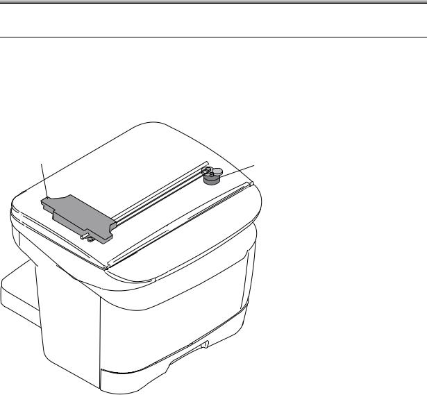
The covers around the laser scanner unit are identified by the following label [1].
[1]
F-1-4
1-8

|
Chapter 1 |
|
|
1.4.3 Safety of Toner |
0002-8619 |
The machine's toner is a non toxic material composed of plastic, iron, and small amounts of dye.
 Do not put the toner into fire. It may explode.
Toner on the Skin or Clothes
1.If your skin or clothes came into contact with toner, wash with water at once.
2.Do not use warm or hot water, which will cause the toner to jell, permanently fusing it with the fibers of the clothes.
3.Do not bring toner into contact with vinyl material. They are likely to react with each other.
1-9

Chapter 2 TECHNICAL
REFERENCE

Contents
2.1 |
Document Feed and Exposure System.............................................................................................................. |
2 1 |
2.1.1 Overview/Configuration ............................................................................................................................. |
2 1 |
|
|
2.1.1.1 Overview ............................................................................................................................................. |
2 1 |
2.2 |
Laser Exposure.................................................................................................................................................. |
2 2 |
2.2.1 Overview/Configuration ............................................................................................................................. |
2 2 |
|
|
2.2.1.1 Overview ............................................................................................................................................. |
2 2 |
2.3 |
Image Formation ............................................................................................................................................... |
2 4 |
2.3.1 Overview/Configuration ............................................................................................................................. |
2 4 |
|
|
2.3.1.1 Overview ............................................................................................................................................. |
2 4 |
2.4 |
Pickup and Feed System.................................................................................................................................... |
2 6 |
2.4.1 Overview/Configuration ............................................................................................................................. |
2 6 |
|
|
2.4.1.1 Overview ............................................................................................................................................. |
2 6 |
2.4.2 Detection Jams............................................................................................................................................ |
2 7 |
|
|
2.4.2.1 Jam Detection Outline......................................................................................................................... |
2 7 |
|
2.4.2.2 Delay Jams........................................................................................................................................... |
2 8 |
|
2.4.2.3 Stationary Jams.................................................................................................................................... |
2 8 |
|
2.4.2.4 Other Jams........................................................................................................................................... |
2 8 |
2.5 |
Fixing Unit ........................................................................................................................................................ |
2 9 |
2.5.1 Overview/Configuration ............................................................................................................................. |
2 9 |
|
|
2.5.1.1 Overview ............................................................................................................................................. |
2 9 |
2.5.2 Protective Function................................................................................................................................... |
2 10 |
|
|
2.5.2.1 Protective Mechanisms...................................................................................................................... |
2 10 |
|
2.5.2.2 Detecting a Fault in the Fixing Assembly......................................................................................... |
2 11 |
2.6 |
External and Controls...................................................................................................................................... |
2 12 |
2.6.1 Power Supply............................................................................................................................................ |
2 12 |
|
|
2.6.1.1 Energy Saving Function.................................................................................................................... |
2 12 |
Chapter 2
2.1 Document Feed and Exposure System
2.1.1 Overview/Configuration
2.1.1.1 Overview |
0007-8185 |
[2]
[1]
F-2-1
T-2-1
[1]Flatbed motor
[2]CCD unit
The CCD unit driven by the flatbed motor reads out image data of a document on the platen glass.
2-1

Chapter 2 Running H/F 5
2.2 Laser Exposure
2.2.1 Overview/Configuration
2.2.1.1 Overview |
0002-8624 |
[8]
[1]
[7]
[6]
[2]
[3]
[5]
[4]
F-2-2
|
T-2-2 |
[1] Laser driver PCB |
[5] Imaging lends |
[2] BD sensor |
[6] Scanner motor |
[3] Reflecting mirror |
[7] 4 facet mirror |
[4] Photosensitive drum |
[8] Cylindrical lens |
The machine's laser scanner assembly consists of the laser driver and the scanner motor, which are driven by signals coming from the engine controller.
The laser driver serves to turn on the laser diode according to the laser control signal and video signals from the engine controller.
The laser beam moves thorough the collimator less and the cylindrical lens to reach the 4 facet mirror rotating at a specific speed.
2-2
Loading...