


 Loading...
MULTIMEDIA PROJECTOR
LV-7375
LV-7370
LV-7275
LV-8300
User’s Manual
The projector's model name indicated on the projector's label are LV-7375, LV-7375(E),LV-7370, LV-7370(E), LV-7275, LV-7275(E), LV-8300 and LV-8300(E) respectively.
The models are referred to as LV-7375,LV-7370, LV-7275, and LV-8300 throughout the user's manual except some of the specifications pages.
ENG
Important Information
Safety Cautions
Precautions
Please read this manual carefully before using your Canon LV-7375/LV-7370/LV-7275/LV-8300 projector and keep the manual handy for future reference. Your serial number is located on the bottom of your projector. Record it here:
CAUTION
To turn off main power, be sure to remove the plug from power outlet.
The power outlet socket should be installed as near to the equipment as possible, and should be easily accessible.
CAUTION
TO PREVENT SHOCK, DO NOT OPEN THE CABINET.
NO USER-SERVICEABLE PARTS INSIDE.
REFER SERVICING TO QUALIFIED SERVICE PERSONNEL.
This symbol warns the user that uninsulated voltage within the unit may be sufficient to cause electrical shock. Therefore, it is dangerous to make any kind of contact with any part inside of the unit.
This symbol alerts the user that important information concerning the operation and maintenance of this unit has been provided.
The information should be read carefully to avoid problems.
WARNING: TO PREVENT FIRE OR SHOCK, DO NOT EXPOSE THIS UNIT TO RAIN OR MOISTURE.
DO NOT USE THIS UNIT’S PLUG WITH AN EXTENSION CORD OR IN AN OUTLET UNLESS ALL THE PRONGS CAN BE FULLY INSERTED.
DO NOT OPEN THE CABINET. THERE ARE HIGH-VOLTAGE COMPONENTS INSIDE. ALL SERVICING MUST BE DONE BY QUALIFIED SERVICE PERSONNEL.
Machine Noise Information Regulation - 3. GPSGV,
The highest sound pressure level is less than 70 dB (A) in accordance with EN ISO 7779.
CAUTION
Avoid displaying stationary images for a prolonged period of time.
Doing so can result in these images being temporarily sustained on the surface of the LCD panel.
If this should happen, continue to use your projector. The static background from previous images will disappear.
CAUTION
Do not put the projector on its side when the lamp is turned on.
Doing so may cause damage to the projector.
WARNING TO CALIFORNIA RESIDENTS:
Handling the cables supplied with this product will expose you to lead, a chemical known to the State of California to cause birth defects or other reproductive harm. Wash hands after handling.
Important Information
Federal Communication Commission Notice
Multimedia Projector, Model : LV-7375, LV-7370, LV-7275, and LV-8300
This device complies with Part 15 of the FCC Rules. Operation is subject to the following two conditions:
(1) This device may not cause harmful interference, and (2) this device must accept any interference received, including interference that may cause undesired operation.
Note : This equipment has been tested and found to comply with the limits for a Class B digital device, pursuant to part 15 of the FCC Rules. These limits are designed to provide reasonable protection against harmful interference in a residential installation. This equipment generates, uses and can radiate radio frequency energy and, if not installed and used in accordance with the instructions, may cause harmful interference to radio communications. However, there is no guarantee that interference will not occur in a particular installation. If this equipment does cause harmful interference to radio or television reception, which can be determined by turning the equipment off and on, the user is encouraged to try to correct the interference by one or more of the following measures :
–Reorient or relocate the receiving antenna.
–Increase the separation between the equipment and receiver.
–Connect the equipment into an outlet on a circuit different from that to which the receiver is connected.
–Consult the dealer or an experienced radio/TV technician for help.
The cable with the ferrite core provided with the projector must be used with this equipment in order to comply with Class B limits in Subpart B of Part 15 of the FCC rules.
Use of shielded cable is required to comply with class B limits in Subpart B of Part 15 of FCC Rules.
Do not make any changes or modifications to the equipment unless otherwise specified in the instructions. If such changes or modifications should be made, you could be required to stop operation of the equipment.
Canon U.S.A., Inc.
One Canon Plaza, Lake Success, NY 11042, U.S.A.
Tel No. (516)328-5600
Canadian Radio Interference Regulations
This Class B digital apparatus complies with Canadian ICES-003.
Réglementation canadienne sur les intérferences radio
Cet appareil numérique de la classe B est conforme à la norme NMB-003 du Canada.
European Union (and EEA) only.
These symbols indicate that this product is not to be disposed of with your household waste, according to the WEEE Directive (2002/96/EC), the Battery Directive (2006/66/EC) and/or your national laws implementing those Directives.
If a chemical symbol is printed beneath the symbol shown above, in accordance with the Battery Directive, this indicates that a heavy metal (Hg = Mercury, Cd = Cadmium, Pb = Lead) is present in this battery or accumulator at a concentration above an applicable threshold specified in the Battery Directive.
This product should be handed over to a designated collection point, e.g., on an authorized one-for-one basis when you buy a new similar product or to an authorized collection site for recycling waste electrical and electronic equipment (EEE) and batteries and accumulators. Improper handling of this type of waste could have a possible impact on the environment and human health due to potentially hazardous substances that are generally associated with EEE.
Your cooperation in the correct disposal of this product will contribute to the effective usage of natural resources.
For more information about the recycling of this product, please contact your local city office, waste authority, approved scheme or your household waste disposal service or visit www.canon-europe.com/environment.
(EEA: Norway, Iceland and Liechtenstein)
ii
Important Information
LAMP HANDLING
PRECAUTIONS
This projector uses a high-pressure mercury lamp which must be handled carefully and properly as mentioned below.
•A lamp may explode with a loud sound or burn out due to a shock, scratch, or expiration of lifetime.
•The lamp life may differ from lamp to lamp and according to the environment of use. There is not guarantee of the same lifetime for each lamp. Some lamps may fail or terminate their life in a shorter period of time than other similar lamps.
•A lamp gradually becomes darker with time of use.
•If the projector indicates that the lamp should be replaced (i.e., the LAMP indicator blinks red rapidly), chances of explosion become higher. Replace the lamp with a new one immediately.
•Always keep your face away from the exhaust vent so that you do not suffer from the gas and broken shards of the lamp.
 IF A LAMP EXPLODES
If a lamp explodes, the gas and broken shards may scatter inside the projector and they may come out of the exhaust vent. The gas contains toxic mercury.
Open windows and doors for ventilation.
If you inhale the gas or the shards of the broken lamp enter your eyes or mouth, consult the doctor immediately.
If a lamp explodes, its shards may scatter inside the projector. Ask the Canon service representative to clean and check the inside of the projector and replace the lamp.
DISPOSAL OF WASTE LAMP
Dispose of the mercury lamp of the projector according to the local regulation just like the fluorescent lamp.
Lamp Replacement
•To replace the lamp, follow all instructions provided on page 69.
•Be sure to replace the lamp when the message [Replace with the new lamp.] appears. If you continue to use the lamp after the lamp has reached the end of its usable life, the lamp bulb may shatter, and pieces of glass may be scattered in the lamp case. Do not touch them as the pieces of glass may cause injury.
If this happens, contact your dealer for lamp replacement.
CAUTION
When removing the lamp from a ceiling-mounted projector, make sure that no one is under the projector. Glass fragments could fall if the lamp has been burned out.
NOTE FOR CUSTOMERS IN THE US
Hg LAMP(S) INSIDE THIS PRODUCT CONTAIN MERCURY AND MUST BE RECYCLED OR DISPOSED OF ACCORDING TO LOCAL, STATE OR FEDERAL LAWS.
iii
Important Information
For UK only: In UK, a BS approved power cord with moulded plug has a Black (five Amps) fuse installed for use with this equipment. If a power cord is not supplied with this equipment please contact your supplier.
Important Safeguards
These safety instructions are to ensure the long life of your projector and to prevent fire and shock. Please read them carefully and heed all warnings.
 Installation
•Do not place the projector in the following conditions:
-on an unstable cart, stand, or table.
-near water, baths or damp rooms.
-in direct sunlight, near heaters or heat radiating appliances.
-in a dusty, smoky or steamy environment.
-on a sheet of paper or cloth, rugs or carpets.
•If you wish to have the projector installed on the ceiling:
-Do not attempt to install the projector yourself.
-The projector must be installed by qualified technicians in order to ensure proper operation and reduce the risk of bodily injury.
-In addition, the ceiling must be strong enough to support the projector and the installation must be in accordance with any local building codes.
-Please consult your dealer for more information.
Do Not Use in the Following Environments
Do not install the projector in a humid or dusty place or a place where there is much oily smoke or cigarette smoke. Optical parts such as a lens and mirror are stained, resulting in poor picture.
Do not use the projector in a place where the temperature becomes very high or low.
Operating temperature: +5°C to +40°C Storage temperature: -10°C to +50°C (Quiet mode selected automatically at 95°F to 104°F / 35°C to 40°C)
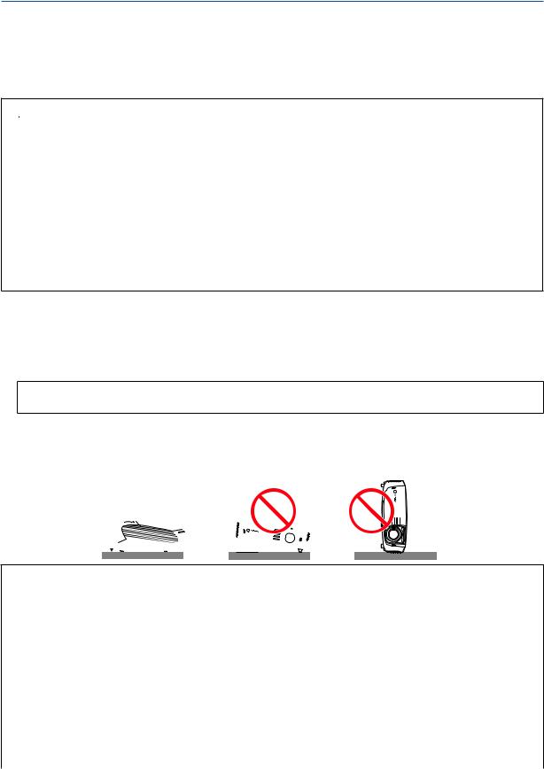
Place the projector in a horizontal position
The tilt angle of the projector should not exceed 10 degrees, nor should the projector be installed in any way other than the desktop and ceiling mount, otherwise lamp life could decrease dramatically.
10˚


 Fire and Shock Precautions
•Ensure that there is sufficient ventilation and that vents are unobstructed to prevent the build-up of heat inside projector. Allow at least 1 m (3.3') of space between your projector and a wall.
•Prevent foreign objects such as paper clips and bits of paper from falling into your projector. Do not attempt retrieve any objects that might fall into your projector. Do not insert any metal objects such as a wire or screwdriver into your projector. If something should fall into your projector, disconnect it immediately and have the object removed by a qualified service personnel.
•Do not place any objects on top of the projector.
•Do not touch the power plug during a thunderstorm. Doing so can cause electrical shock or fire.
•The projector is designed to operate on power source voltages indicated on the rating label on the projector. Ensure that your power fits this requirement before attempting to use your projector.
•Do not look into the lens while the projector is on. Serious damage to your eyes could result.
iv

Important Information
•Keep any items such as magnifying glass out of the light path of the projector. The light being projected from the lens is extensive, therefore any kind of abnormal objects that can redirect light coming out of the lens, can cause unpredictable outcome such as fire or injury to the eyes.
•Do not cover the lens with the black lens cover or equivalent while the projector is on. Doing so can lead to melting the cap and possibly burning your hands due to the heat emitted from the light output.
•Do not place any objects, which are easily affected by heat, in front of the projector lens or a projector exhaust
Doing so could lead to the object melting or getting your hands burned from the heat that is emitted from the output and exhaust.
•Handle the power cord carefully. A damaged or frayed power cord can cause electric shock or fire.
-Do not use any power cords than the supplied one.
-Do not bend or tug the power cord excessively.
-Do not place the power cord under the projector, or any heavy object.
-Do not cover the power cord with other soft materials such as rugs.
-Do not heat the power cord
-Do not handle the power plug with wet hands.
•Turn off the projector, unplug the power cord and have the projector serviced by a qualified service personnel under the following conditions:
-When the power cord or plug is damaged or frayed.
-If liquid has been spilled into the projector, or if it has been exposed to rain or water.
-If the projector does not operate normally when you follow the instructions described in this user's manual.
-If the projector has been dropped or the cabinet has been damaged.
-If the projector exhibits a distinct change in performance, indicating a need for service.
•Disconnect the power cord and any other cables before carrying the projector
•Turn off the projector and unplug the power cord before cleaning the cabinet or replacing the lamp.
•Turn off the projector and unplug the power cord if the projector is not to be used for an extended period of time.
•When using a LAN cable:
For safety, do not connect to the connector for peripheral device wiring that might have excessive voltage.
CAUTION
•Do not try to touch the ventilation outlet on the left side (when seen from the front) as it can become heated while the projector is turned on.
•Do not use the tilt-foot for purposes other than originally intended. Misuses such as gripping the tilt-foot or hanging on the wall can cause damage to the projector.
•Select [High] in Fan mode if you continue to use the projector for consecutive days. (From the menu, select [Setup]→ [Options (1)] → [Fan mode] → [High].) Fan noise increases noticeably in High mode. See page 61.
•Do not turn off the AC power for 60 seconds after the lamp is turned on and while the POWER indicator is blinking green. Doing so could cause premature lamp failure.
•Do not hold the lens part when carrying the projector.
Doing so could cause the focus ring to rotate, resulting in accidental dropping of the projector.

Important Information
CARRYING/TRANSPORTING THE PROJECTOR
This projector is a precision machine. Do not give a strong shock to the projector or turn it down.
Thoroughly read "Use Caution When Carrying or Transporting the Projector" below and install the lens cover before carrying the projector. When transporting the projector by train or airplane, use a highly crashworthy transport case.
Use Caution When Carrying or Transporting the Projector
The carrying bag is intended for protection from dust and scratches on the surface of the cabinet, and it is not designed to protect the projector from external shocks. When carrying the projector with it put in the carrying bag, do not give a shock to it, drop it, or place anything on it.
Do not transport the projector through a courier or transport service with the carrying bag. The projector can damage.
 Remote Control Precautions
•Handle the remote control carefully.
•If the remote control gets wet, wipe it dry immediately.
•Avoid excessive heat and humidity.
•Do not heat, take apart, or throw batteries into fire.
•If you will not be using the remote control for a long time, remove the batteries.
•Ensure that you have the batteries' polarity (+/-) aligned correctly.
•Do not use new and old batteries together, or use different types of batteries together.
•Dispose of used batteries according to your local regulations.
About [High altitude] mode
•Set [Fan mode] to [High altitude] when using the projector at altitudes approximately 5500 feet/1600 meters or higher. See page 61.
Using the projector at altitudes approximately 5500 feet/1600 meters or higher without setting to [High altitude] can cause the projector to overheat and the protector could shut down. Furthermore, the projector could not turn on due to the increased temperature of the lamp after power off. If these happen, wait a couple minutes and turn on the projector.
Fan noise increases noticeably in [High altitude]. See page 61.
•Using the projector at altitudes less than approximately 5500 feet/1600 meters and setting to [High altitude] can cause the lamp to overcool, causing the image to flicker. Switch [Fan mode] to [Auto].
•Using the projector at altitudes approximately 5500 feet/1600 meters or higher can shorten the life of optical components such as the lamp.
About Copyright of original projected pictures:
Please note that using this projector for the purpose of commercial gain or the attraction of public attention in a venue such as a coffee shop or hotel and employing compression or expansion of the screen image with the following functions may raise concern about the infringement of copyrights which are protected by copyright law.
[Aspect], [Keystone adjustment], Magnifying (D.ZOOM) feature and other similar features.
vi

Table of Contents
Important Information .......................................................................................... |
i |
1. Introduction ......................................................................................................... |
1 |
What's in the Box?......................................................................................................... |
1 |
Introduction to the Projector.......................................................................................... |
2 |
Part Names of the Projector.......................................................................................... |
4 |
Top Features............................................................................................................ |
5 |
Terminal Panel Features.......................................................................................... |
6 |
Part Names of the Remote Control............................................................................... |
7 |
Battery Installation.............................................................................................. |
9 |
Remote Control Precautions............................................................................... |
9 |
Operating Range for Wireless Remote Control.................................................. |
9 |
2. Installation and Connections .................................................................. |
10 |
Setting Up the Screen and the Projector..................................................................... |
11 |
Selecting a Location (LV-7375/LV-7370/LV-7275)................................................ |
11 |
Throw Distance and Screen Size..................................................................... |
11 |
Selecting a Location (LV-8300).............................................................................. |
12 |
Throw Distance and Screen Size..................................................................... |
12 |
Making Connections.................................................................................................... |
14 |
Enabling the computer’s external display.............................................................. |
14 |
Connecting Your PC or Macintosh Computer........................................................ |
14 |
When Viewing a DVI Digital Signal................................................................... |
16 |
Using Two Analog Computer Inputs Simultaneously........................................ |
17 |
Connecting an External Monitor............................................................................. |
18 |
Connecting Your Audio-Video Equipment with Component Output....................... |
19 |
Connecting Your Audio-Video Equipment with Video/S-Video Output.................. |
20 |
Connecting a Digital Video Signal.......................................................................... |
21 |
Connecting to a Network........................................................................................ |
22 |
Connecting the Supplied Power Cord.................................................................... |
23 |
3. Projecting an Image (Basic Operation) ............................................. |
24 |
Turning on the Projector.............................................................................................. |
24 |
Note on Startup Screen (Menu Language Select screen)..................................... |
25 |
Selecting a Source...................................................................................................... |
26 |
Adjusting the Picture Size and Position....................................................................... |
28 |
Correcting Keystone Distortion.................................................................................... |
31 |
Automatically Optimizing on RGB Image.................................................................... |
34 |
Turning Up or Down Volume....................................................................................... |
34 |
Turning off the Projector.............................................................................................. |
35 |
After Use...................................................................................................................... |
36 |
vii

|
Table of Contents |
4. Convenient Features .................................................................................... |
37 |
Turning Off the Image and Sound............................................................................... |
37 |
Freezing a Picture....................................................................................................... |
37 |
Enlarging a Picture...................................................................................................... |
37 |
Preventing the Unauthorized Use of the Projector [Password]................................... |
38 |
Network and Alert Mail Settings by Using an HTTP Browser...................................... |
41 |
5. Using On-Screen Menu ............................................................................... |
45 |
Using the Menus.......................................................................................................... |
45 |
Menu Elements............................................................................................................ |
46 |
List of Menu Items....................................................................................................... |
47 |
Menu Descriptions & Functions [Input]........................................................................ |
49 |
Menu Descriptions & Functions [Adjustment].............................................................. |
50 |
Menu Descriptions & Functions [Setup]...................................................................... |
57 |
Menu Descriptions & Functions [Information].............................................................. |
64 |
Menu Descriptions & Functions [Reset]...................................................................... |
66 |
6. Maintenance ..................................................................................................... |
67 |
Cleaning or Replacing the Filter................................................................................. |
67 |
Cleaning the Cabinet and the Lens............................................................................ |
68 |
Replacing the Lamp.................................................................................................... |
69 |
7. Appendix ............................................................................................................. |
72 |
Troubleshooting.......................................................................................................... |
72 |
Specifications............................................................................................................. |
75 |
Cabinet Dimensions................................................................................................... |
77 |
Pin Assignments of D-Sub ANALOG IN-1 Input Connector....................................... |
78 |
Compatible Input Signal List....................................................................................... |
79 |
Relationship between Screen Size and Projection Distance...................................... |
80 |
PC Control Codes and Cable Connection.................................................................. |
82 |
Troubleshooting Check List........................................................................................ |
83 |
viii
1. Introduction
What's in the Box?
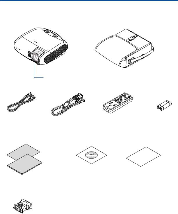
Make sure your box contains everything listed. If any pieces are missing, contact your dealer. Please save the original box and packing materials if you ever need to ship your projector.
Projector
Soft case
Lens cover
AC power cord |
VGA cable |
Remote control |
Batteries (AAA 2) |
(4.5 m / 14.8’) |
(1.8 m / 5.9’) |
|
|
|
[7N520068] |
|
|
|
Quick |
Start |
|
Guide |
|
Important |
|
Information |
|
Quick Start Guide |
CD-ROM |
Warranty |
Important Information |
User’s manual |
|
DVI to VGA adapter
1. Introduction
Introduction to the Projector
This section introduces you to your new projector and describes the features and controls.
Congratulations on Your Purchase of The Projector
The LV-7375/LV-7370/LV-7275/LV-8300 is one of the very best projectors available today. The projector enables you to project precise images up to 300 inches across (measured diagonally) from your PC or Macintosh computer (desktop or notebook), or audio-video equipment.
You can use the projector on a tabletop or cart, from behind a screen, or permanently mounted on a ceiling*1. The remote control can be used wirelessly.
*1 Do not attempt to mount the projector on a ceiling yourself.
The projector must be installed by qualified technicians in order to ensure proper operation and reduce the risk of bodily injury.
In addition, the ceiling must be strong enough to support the projector and the installation must be in accordance with any local building codes. Please consult your dealer for more information.
Features you'll enjoy:
•Portable LCD projector with high brightness
The LCD projector in a compact design provides high brightness.
•Quick start & Direct Power Off
Eight seconds after turning on the power, the projector is ready to display PC or video images.
The projector has a feature called “Direct Power Off”. This feature allows the projector to be turned off (even when projecting an image) using a power strip equipped with a switch and a breaker.
NOTE: If you turn on the projector immediately after the lamp is turned off or when the temperature is high, the fans run without displaying an image for some time.
•Direct Power on and Power Management features
The Direct power on (AC), Direct power on (Comp1), Power management, and Off timer features eliminate the need to always use the POWER button on the remote control or projector cabinet.
(For Direct power on (AC), Direct power on (Comp1), and Power management, see page 63; for Off timer, see page 62.)
•A variety of input ports and a comprehensive array of system control interfaces
This projector supports input signals on the following ports: DVI-I connector (DVI-I 29 Pin) with HDCP compatible, 15pin D-Sub, composite and S-video.
•7W built-in speaker for an integrated audio solution
Powerful 7 watt speaker provides volume need for large rooms.
•Auto vertical keystone correction
Auto keystone feature allows the projector to detect its tilt and correct vertical distortion automatically. (page 33)
•Supporting up to UXGA resolution
High resolution display - up to UXGA compatible, XGA (LV-7375/LV-7370/LV-7275) / WXGA (LV-8300) native resolution.
•Five picture preset modes for user adjustable picture and color settings
Each picture preset mode can be customized and memorized according to your preference. (page 50)
•Preventing unauthorized use of the projector
Enhanced smart security settings for password protection (page 38), cabinet key lock (page 60), and anti-theft security cable lock (page 4) to help prevent unauthorized access, adjustments and theft deterrence.
•Notifying an error message via e-mail when using wired LAN
The Alert Mail feature notifies your computer of an error message via e-mail when using wired LAN. The error message will be notified when the projector lamp has reached the end of its usable life or an error occurs in the projector (page 43). You can configure the network settings of the projector on your computer. (page 41)
•3 W standby power consumption
Setting [Power-saving] mode for [Standby mode] in the menu reduces standby power consumption to 3 watts. (page 62)

1. Introduction
About this user's manual
The fastest way to get started is to take your time and do everything right the first time. Take a few minutes now to review the user's manual. This may save you time later on. At the beginning of each section of the manual you'll find an overview. If the section doesn't apply, you can skip it.
•Macintosh, Mac OS X and PowerBook are trademarks of Apple Inc. registered in the U.S. and other countries.
•Microsoft, Windows, and Internet Explorer are either registered trademarks or trademarks of Microsoft Corporation in the United States and/or other countries.
•MicroSaver is a registered trademark of Kensington Computer Products Group, a division of ACCO Brands.
•Other product and company names mentioned in this user’s manual may be the trademarks or registered trademarks of their respective holders.
1. Introduction
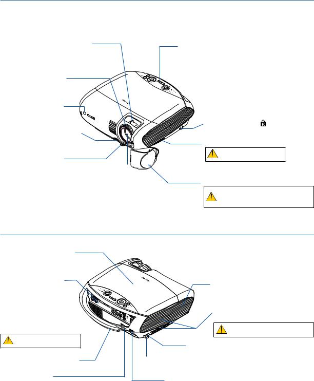
Part Names of the Projector
Front/Top
Zoom Lever |
Controls |
|
|
(See page 30) |
|
||
(See page 6) |
|||
|
|||
Focus Ring |
|
|
|
(See page 30) |
|
|
|
Remote sensor |
|
|
|
(See page 9) |
|
|
|
|
|
Built-in Security Slot ( )* |
|
Adjustable Tilt Foot Lock Button |
|
Ventilation (inlet) / Filter Cover |
|
(See page 29) |
|
||
|
(See page 67) |
||
|
|
||
|
|
Do not block this vent. |
|
Adjustable Tilt Foot |
|
Troubles or fire can result. |
|
(See page 29) |
Lens |
|
|
|
|
||
|
|
Lens Cover |
|
|
|
Be sure to remove the lens cover dur- |
|
* This security slot supports the MicroSaver ® Security System. |
ing projection. The cap can deform or |
||
fire can occur. |
|||
|
|
||
Rear
Lamp Cover
(See page 68)
Terminal Panel
(See page 6)
Ventilation (inlet) / Filter Cover (See page 67)
Do not block this vent.
Troubles or fire can result.
Carrying Handle
Main Power Switch
When you plug the supplied power cord into an active wall outlet and turn on the Main Power, the
POWER indicator turns orange and the projector is in standby mode.
(See page 24)
Monaural Speaker (7W)
Ventilation (outlet)
Heated air is exhausted from here.
Do not block this vent. Troubles or fire can result.
Spacer (black rubber)
A spacer is provided for leveling the projector.
Rear Foot To fine-adjust the height of the rear foot, remove the spacer and rotate the rear
foot to the desired height.
AC Input
Connect the supplied power cord’s two-pin plug here, and plug the other end into an active wall outlet. (See page 23)
1. Introduction
Top Features
8 7
3
4 |
|
|
|
|
1 |
2 |
5 |
6 9 |
10 |
1.POWER Button ( )
)
Use this button to turn the power on and off when the main power is supplied and the projector is in standby mode.
To turn on the projector, press and hold this button for about 1 second. To turn off the projector, press this button twice.
2.POWER Indicator
When this indicator is green, the projector is on; when this indicator is orange, it is in standby mode. See the Power Indicator section on page 72 for more details.
3.STATUS Indicator
If this light blinks red rapidly, it indicates that an error has occurred, the lamp cover is not attached properly or the projector has overheated. If this light remains orange, it indicates that you have pressed a cabinet key while the Key lock is enabled. See the STATUS Indicator section on page 72 for more details.
4.LAMP Indicator
If this light blinks red rapidly, it's warning you that the lamp has reached the end of its usable life. After this light appears, replace the lamp as soon as possible (See page 69). If this is lit green continually, it indicates that the lamp mode is set to Quiet. See the LAMP Indicator section on page 72 for more details.
5.INPUT Button
Selecting from INPUT List
Press and quickly release the INPUT button to display the INPUT list. Each time the INPUT button is pressed, the input source will change as follows:
Computer 1 → Computer 2 (Digital) → Computer 2 (Analog) → VIDEO → S-VIDEO → Computer 1 → ...
To display the selected source, press the OK button or allow 2 seconds to elapse.
Detecting the Signal Automatically
Press and hold the INPUT button for a minimum of 2 seconds, the projector will search for the next available input source. Each time you press and hold the INPUT button for a minimum of 2 seconds, the input source will change as follows:
Computer 1 → Computer 2 (Digital) → Computer 2 (Analog) → VIDEO → S-VIDEO → Computer 1 → ...
6.AUTO PC Button
Use this button to adjust an analog RGB source for an optimal picture. See page 34.
7.MENU Button
Displays the menu. See page 45.
8.


 / VOL (+/–) / KEYSTONE (
 ) Buttons
See page 45.

 : Use these buttons to select the menu of the item you wish to adjust.
When no menus appear, these buttons work as a keystone control. See page 31.

 : Use these buttons to change the level of a selected menu item. A press of the
  button executes the selection. When no menus appear, these buttons work as a volume control. See page 34.
9.OK Button
Executes your menu selection and activates items selected from the menu.
10.BACK Button
Pressing this button will return to the previous menu.
While you are in the main menu, pressing this button will close the menu.
1. Introduction
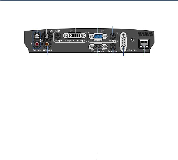
Terminal Panel Features
8 |
7 |
3 |
2 |
||||
|
|
|
|
|
|
|
|
|
|
|
|
|
|
|
|
|
|
|
|
|
|
|
|
6
1.Computer 1 Input Connector [ANALOG IN-1] (Mini D-Sub 15 Pin)
Connect your computer or other analog RGB equipment such as IBM compatible or Macintosh computers. Use the supplied VGA cable to connect to your computer. This also serves as a component input connector that allows you to connect a component video output of audio-video equipment.
See page 14, 17, 19.
2.Computer 2 Input Connector [DIGITAL IN/ANALOG IN-2] (DVI-I 29 Pin)
Connect the DVI output of your computer or other digital RGB equipment such as IBM compatible or Macintosh computers.
You can also use the supplied DVI to VGA adapter to connect the output of analog RGB equipment.
See page 16, 17, 21.
3.AUDIO IN Mini Jack (Stereo Mini)
This is where you connect the audio output from your computer or audio-video equipment when connected to the ANALOG IN-1 or 2 input. A commercially available audio cable is required.
See page 14, 16, 18, 19, 21.
4.MONITOR OUT Connector [ ] (Mini D-Sub 15 Pin)
You can use this connector to loop your computer image to an external monitor from the RGB input source (ANALOG IN-1).
This connector outputs RGB signal in standby mode. See page 18.
5.AUDIO OUT Mini Jack (Stereo Mini)
You can use this jack to output sound from the currently selected source (COMPUTER, VIDEO or S-VIDEO). Output sound level can be adjusted in accordance with the sound level of the internal speaker.
1 3
4 |
5 |
9 |
10 |
Note that this cannot be used as a headphone jack. (When audio equipment is connected, the projector speaker is disabled.)
When a cable mini-plug is inserted into this jack, both the right and left audio signals are not mixed, but separate. For example, when a cable mini-plug is inserted into the left AUDIO IN jack only, only left sound is output.
6.VIDEO IN Connector (RCA)
Connect audio-video equipment here to project video. See page 20.
7.S-VIDEO IN Connector (Mini DIN 4 Pin)
Here is where you connect the S-Video input from audio-video equipment.
See page 20.
NOTE: S-Video provides more vivid color and higher resolution than the traditional composite video format.
8.AUDIO IN Jacks L/R (RCA)
These are your left and right channel audio inputs for stereo sound from a Video/S-Video source.
See page 20, 21.
9.SERVICE PORT (D-Sub 9 Pin)
Use this port to connect a computer or control system.
This enables you to control the projector using serial communication protocol. If you are writing your own program, typical PC control codes are on page 82.
10.LAN Port [ ] (RJ-45)
Use this port when controlling your projector in LAN connection from a computer. Use a commercially available LAN cable (10 Base-T/100 Base-T) to connect the projector to the computer. See page 22.
1. Introduction
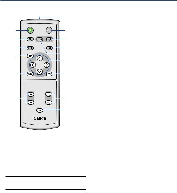
Part Names of the Remote Control
|
|
|
1 |
2 |
POWER |
INFO. |
|
|
|
3 |
|
4 |
IMAGE INPUT |
AUTO PC |
6 |
|
|
||
7 |
ASPECT |
BLANK |
8 |
|
|
||
9 |
MENU |
|
5 |
|
|
10 |
|
|
|
|
|
11 |
|
BACK |
12 |
|
|
|
|
|
VOL |
D.ZOOM |
|
13 |
|
|
14 |
FREEZE |
15 |
|
|
RD-439E |
|
5.INPUT Button
Selecting from INPUT List
Press and quickly release the INPUT button to display the INPUT list. Each time the INPUT button is pressed, the input source will change as follows:
Computer 1 → Computer 2 (Digital) → Computer 2 (Analog) → VIDEO → S-VIDEO → Computer 1 → ...
To display the selected source, press the OK button or allow 2 seconds to elapse.
Detecting the Signal Automatically
Press and hold the INPUT button for a minimum of 2 seconds, the projector will search for the next available input source. Each time you press and hold the INPUT button for a minimum of 2 seconds, the input source will change as follows:
Computer 1 → Computer 2 (Digital) → Computer 2 (Analog) → VIDEO → S-VIDEO → Computer 1 → ...
6.AUTO PC Button
Use this button to adjust an analog RGB source for an optimal picture. See page 34.
7.ASPECT Button
Press this button once to display the Aspect select menu. Keep pressing will change aspect ratios. See page 54.
1.Infrared Transmitter
Direct the remote control toward the remote sensor on the projector cabinet.
2.POWER Button
When the main power is on, you can use this button to turn your projector on.
NOTE: To turn on the projector, press and hold the POWER button for about 1 second.
You can use this button to turn your projector off.
NOTE: To turn off the projector, press this button twice.
3.INFO. Button
Provides the information on the current signal and projector settings. See page 64.
4.IMAGE Button
Press this button to display the Image adjustment menu to adjust Image mode, Contrast, Brightness, Sharpness, Color level and Color balance. See pages 50 to 51.
8.BLANK Button
This button turns off the image and sound for a short period of time. Press again to restore the image and sound. See page 37.
9.MENU Button
Displays the menu for various settings and adjustments. See page 45.
10.


 Button
See page 45.

 : Use these buttons to select the menu of the item you wish to adjust.

 : Use these buttons to change the level of a selected menu item. A press of the
  button executes the selection.
When an image is magnified, the 


 button moves the image. See page 37.
11.OK Button
Use this button to enter your menu selection. It works the same way as the OK button on the cabinet. See page 5.
1. Introduction
|
|
|
1 |
2 |
POWER |
INFO. |
|
|
|
3 |
|
4 |
IMAGE |
INPUT AUTO PC |
6 |
|
|
||
7 |
ASPECT |
BLANK |
8 |
|
|
||
|
MENU |
|
5 |
9
 10
10
11


 12
12
BACK
VOL D.ZOOM
13
FREEZE
14
15
RD-439E
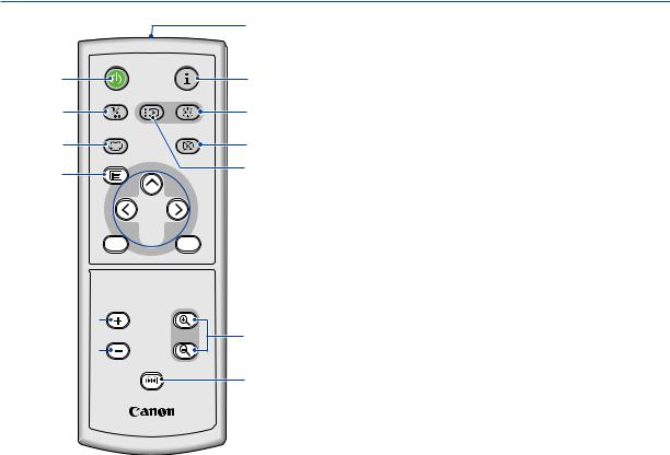
12.BACK Button
It works the same way as the BACK button on the cabinet. See page 5.
13.VOL (+) (–) Button
Press (+) to increase the volume and (–) to decrease it. See page 34.
14.D. ZOOM (+) (–) Button
Use this button to adjust the image size up to 400%.
The image is magnified about the center of the screen. See page 37.
15.FREEZE Button
This button will freeze a picture. Press again to resume motion. See page 37.
1. Introduction
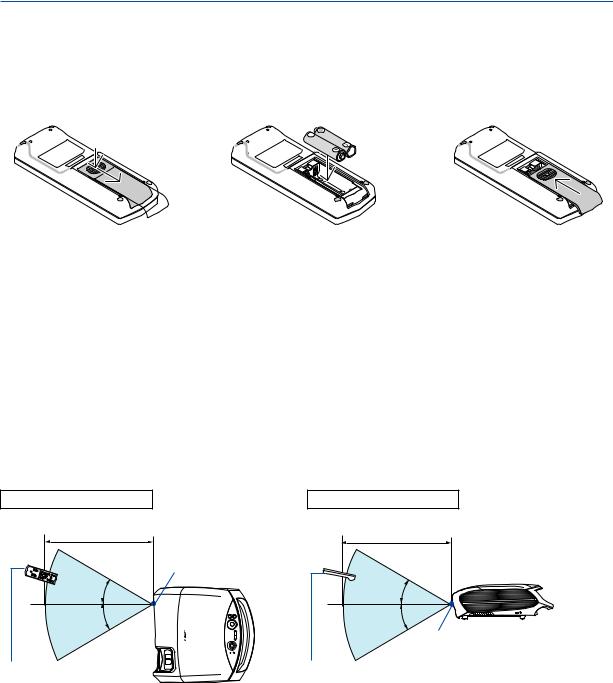
Battery Installation
1Press firmly and slide the battery cover off.
2Remove both old batteries and install new ones (AAA). Ensure that you have the batteries' polarity (+/–) aligned correctly.
3Slip the cover back over the batteries until it snaps into place. Do not mix different types of batteries or new and old batteries.
Remote Control Precautions
•Handle the remote control carefully.
•If the remote control gets wet, wipe it dry immediately.
•Avoid excessive heat and humidity.
•Do not heat, take apart, or throw batteries into fire.
•Ensure that you have the batteries' polarity (+/-) aligned correctly.
•If you will not be using the remote control for a long time, remove the batteries.
•Do not place the batteries upside down.
•Do not use new and old batteries together, or use different types of batteries together.
•Dispose of used batteries according to your local regulations.
Operating Range for Wireless Remote Control
Horizontal range |
Vertical range |
7m/22 feet |
7m/22 feet |
|
Remote sensor on |
|
projector cabinet |
30° |
30° |
30° |
30° |
Remote sensor on projector cabinet
Remote control |
Remote control |
•The infrared signal operates by line-of-sight up to a distance of about 7 m (22 feet) and within a 60-degree angle of the remote sensor on the projector cabinet.
•The projector will not respond if there are objects between the remote control and the sensor, or if strong light falls on the sensor. Weak batteries will also prevent the remote control from properly operating the projector.

2. Installation and Connections
This section describes how to set up your projector and how to connect video and audio sources.
1
2 |
3 |
|
To the wall outlet.
Your projector is simple to set up and use. But before you get started, you must first:
Set up a screen and the projector. See page 11, 12.
Connect your computer or audio-video equipment to the projector. See pages 14, 16, 17, 18, 19, 20, 21, 22.Connect the supplied power cord. See page 23.
NOTE: Ensure that the power cord and any other cables are disconnected before moving the projector. When moving the projector or when it is not in use, cover the lens with the lens cover.
10
2. Installation and Connections
Setting Up the Screen and the Projector
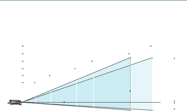
Selecting a Location (LV-7375/LV-7370/LV-7275)
The further your projector is from the screen or wall, the larger the image. The minimum size the image can be is approximately 21" measured diagonally when the projector is roughly 0.8 m (2.6') from the wall or screen. The largest the image can be is 300" when the projector is about 11.3 m (37.0') from the wall or screen. Use the drawing below as a guide.
11.3 m (Zoom min.)
|
|
|
|
|
|
|
|
|
|
|
|
|
|
|
|
|
|
|
|
|
|
|
|
|
|
|
|
|
|
|
|
9.4 m (Zoom max.) |
|
|
|
|
|
|
|
|
|
|
|
|
|
|
|||||
|
|
|
|
|
|
|
|
|
|
|
Zoom (max.) |
|
|
|
|
|
|
|
|
||||||
|
|
|
|
|
6.2 m |
|
|
|
|
|
|
300" |
|
|
|
|
|
|
|
|
|
||||
|
|
|
|
|
|
|
|
|
|
|
|
|
|
|
|
|
|
|
|
|
|
||||
|
|
|
|
|
|
|
|
|
|
|
|
|
|
|
|
300" |
|
|
Zoom (min.) |
|
|
||||
|
|
|
4.7 m |
|
|
|
|
|
200" |
250" |
|
|
|||||||||||||
|
|
|
|
|
|
|
|
|
|
|
|
|
|
|
|
|
|
||||||||
2.5 m |
|
|
|
|
|
|
|
|
|
|
|
|
|
|
|
|
|
|
|
||||||
|
|
|
|
|
|
150" |
|
165" |
|
|
|
|
|
|
|
|
|
|
|
|
|
|
|||
|
|
|
|
|
|
|
|
|
|
|
|
|
|
|
|
|
|
|
|
|
|||||
1.2 m |
|
|
80" |
|
|
|
126" |
|
|
|
|
|
|
|
|
|
|
|
|
H1 |
|
||||
|
|
|
|
|
|
|
|
|
|
|
|
|
|
|
|
|
|
||||||||
|
|
|
|
|
|
|
|
|
|
|
|
|
|
|
|
|
|
|
|
|
|
||||
|
|
|
|
|
|
|
|
|
|
|
|
|
|
|
|
|
|
|
|
|
|
||||
|
|
|
|
|
|
|
|
|
|
|
|
|
|
|
|
|
|
|
|
|
|
|
|
||
|
|
40" |
|
|
67" |
|
|
|
|
|
|
Screen |
|
|
|
|
|
|
|
|
|
|
|
|
|
|
|
|
|
|
|
|
|
|
|
|
|
|
|
|
|
|
|
|
|
|
|
||||
|
|
|
|
|
|
|
|
|
|
|
|
|
|
|
|
|
|
|
|
|
|
|
|
||
|
|
|
|
|
|
|
|
|
|
|
|
|
|
|
|
|
|
|
|
|
|
|
|
|
|
|
|
32" |
|
|
|
|
|
|
|
|
|
|
|
|
|
|
|
|
|
|
|
|
|
|
|
|
|
|
|
|
|
|
|
|
|
|
|
|
|
|
|
|
|
|
|
|
|
|
H2 |
|
|
|
|
|
|
|
|
|
|
|
|
|
|
|
|
|
|
|
|
|
|
||||||
|
|
|
|
|
|
|
|
|
|
|
|
|
|
|
|
|
|
|
|
|
|
|
|
|
|
|
|
Optional axis when image is projected |
|
|
|
|
|
|
|
|
|
|
|
|
|
|
|||||||||
|
|
|
|
|
|
|
|
|
|
|
|
|
|
|
|
||||||||||
|
|
at right angle to the screen. |
|
|
|
|
|
|
|
|
|
|
|
|
|
|
|||||||||
Throw Distance and Screen Size
Screen size |
21" |
25" |
30" |
40" |
60" |
80" |
100" |
150" |
180" |
200" |
250" |
300" |
|
(W×H) cm |
43×32 |
51×38 |
61×46 |
81×61 |
122×91 |
163×122 |
203×152 |
305×229 |
366×274 |
406×305 |
508×381 |
610×457 |
|
Projection |
|
0.8 m |
0.9 m |
1.2 m |
1.9 m |
2.5 m |
3.1 m |
4.7 m |
5.6 m |
6.2 m |
7.8 m |
9.4 m |
|
distance |
– |
||||||||||||
(2.6’) |
(3.0’) |
(3.9’) |
(6.2’) |
(8.2’) |
(10.2’) |
(15.4’) |
(18.4’) |
(20.3’) |
(25.6’) |
(30.8’) |
|||
Zoom (max) |
|
||||||||||||
|
|
|
|
|
|
|
|
|
|
|
|
||
Projection |
0.8 m |
0.9 m |
1.1 m |
1.5 m |
2.2 m |
3.0 m |
3.7 m |
5.6 m |
6.8 m |
7.5 m |
9.4 m |
11.3 m |
|
distance |
|||||||||||||
(2.6’) |
(3.0’) |
(3.6’) |
(4.9’) |
(7.2’) |
(9.8’) |
(12.1’) |
(18.4’) |
(22.3’) |
(24.6’) |
(30.8’) |
(37.1’) |
||
Zoom (min) |
|||||||||||||
|
|
|
|
|
|
|
|
|
|
|
|
||
H1 |
27 cm |
32 cm |
39 cm |
51 cm |
77 cm |
103 cm |
129 cm |
193 cm |
231 cm |
257 cm |
321 cm |
386 cm |
|
(0.9’) |
(1.1’) |
(1.3’) |
(1.7’) |
(2.5’) |
(3.4’) |
(4.2’) |
(6.3’) |
(7.6’) |
(8.4’) |
(10.5’) |
(12.7’) |
||
|
|||||||||||||
H2 |
5 cm |
6 cm |
7 cm |
10 cm |
14 cm |
19 cm |
24 cm |
36 cm |
43 cm |
48 cm |
60 cm |
71 cm |
|
(0.2’) |
(0.2’) |
(0.2’) |
(0.3’) |
(0.5’) |
(0.6’) |
(0.8’) |
(1.2’) |
(1.4’) |
(1.6’) |
(2.0’) |
(2.3’) |
||
|
H1 and H2: H1 is the height of the screen from the intersection of optical axis and screen surface, and H2 is the height of the intersection when an image is projected at right angle to the screen.
•The sizes in the above table have been obtained assuming that the aspect ratio is 4:3. They may vary from the actual sizes depending on the type of the projected image.
11
2. Installation and Connections
Selecting a Location (LV-8300)
The further your projector is from the screen or wall, the larger the image. The minimum size the image can be is approximately 21" measured diagonally when the projector is roughly 0.7 m (2.3') from the wall or screen. The largest the image can be is 300" when the projector is about 10.7 m (35.0') from the wall or screen. Use the drawing below as a guide.
10.7 m (Zoom min.)
|
|
|
|
|
|
|
|
|
|
|
|
|
|
|
|
|
|
|
|
|
|
|
|
|
|
|
|
|
|
|
|
|
8.8 m (Zoom max.) |
|
|
|
|
|
|
|
|
|
|
|
|
|
|
|
|||||
|
|
|
|
|
|
|
|
|
|
|
Zoom (max.) |
|
|
|
|
|
|
|
|
|||||||
|
|
|
|
|
5.9 m |
300" |
|
|
|
|
|
|
|
|
||||||||||||
|
|
|
|
|
|
|
|
|
|
|
|
|
|
|
|
|||||||||||
|
|
|
|
|
|
|
|
|
|
|
|
|
|
|
|
|
|
|
|
|
|
|
||||
|
|
|
|
|
|
|
|
|
|
|
|
|
|
|
|
|
|
|
|
|
|
|
||||
|
|
4.4 m |
|
|
|
|
|
200" |
|
|
|
|
300" |
|
Zoom (min.) |
|
|
|
||||||||
|
|
|
|
|
|
|
|
|
|
|
|
|
||||||||||||||
2.3 m |
|
|
|
|
|
247" |
|
|
|
|
|
|
|
|
|
|
|
|||||||||
|
|
|
|
|
|
|
|
|
|
|
|
|
|
|
|
|
||||||||||
|
|
|
|
|
|
|
|
|
150" |
|
|
|
|
|
|
|
|
|
|
|
|
|
|
|
|
|
1.1 m |
|
|
|
|
166" |
|
|
|
|
|
|
|
|
|
|
|
|
|
|
H1 |
||||||
|
|
|
|
|
|
|
|
|
|
|
|
|
|
|
|
|
|
|
|
|||||||
|
|
|
|
|
80" |
|
|
|
125" |
|
Screen |
|
|
|
|
|
|
|
|
|
|
|
|
|||
|
|
|
|
|
|
|
|
|
|
|
|
|
|
|
|
|
|
|
|
|
||||||
|
|
|
|
|
|
|
|
|
|
|
|
|
|
|
|
|
|
|
|
|
|
|||||
|
|
40" |
|
|
66" |
|
|
|
|
|
|
|
|
|
|
|
|
|
|
|
|
|
|
|
||
|
|
|
|
|
|
|
|
|
|
|
|
|
|
|
|
|
|
|
|
|||||||
|
|
31" |
|
|
|
|
|
|
|
|
|
|
|
|
|
|
|
|
|
|
|
|
|
|
|
|
|
|
|
|
|
|
|
|
|
|
|
|
|
|
|
|
|
|
|
|
|
|
|
|
|
H2 |
|
|
|
|
|
|
|
|
|
|
|
|
|
|
|
|
|
|
|
|
|
|
|
|
|
|
|
|
|
|
|
|
|
|
|
|
|
|
|
|
|
|
|
|
|
|
|
|
|
||||||
|
|
|
|
|
|
|
|
|
|
|
|
|
|
|
|
|
|
|
|
|
|
|
|
|
|
|
|
|
Optional axis when image is projected |
|
|
|
|
|
|
|
|
|
|
|
|
|
|
|
|||||||||
|
|
at right angle to the screen. |
|
|
|
|
|
|
|
|
|
|
|
|
|
|
|
|||||||||
Throw Distance and Screen Size
Screen size |
21” |
25” |
30” |
40” |
60” |
80” |
100” |
150” |
180” |
200” |
250” |
300” |
|
(W x H cm) |
45 x 28 |
54 x 34 |
65 x 40 |
86 x 54 |
129 x 81 |
172 x 108 |
215 x 135 |
323 x 202 |
388 x 242 |
431 x 269 |
538 x 337 |
646 x 404 |
|
|
|
|
|
|
|
|
|
|
|
|
|
|
|
Projection |
|
0.7 m |
0.9 m |
1.1 m |
1.7 m |
2.3 m |
2.9 m |
4.4 m |
5.3 m |
5.9 m |
7.4 m |
8.8 m |
|
distance |
– |
||||||||||||
(2.3’) |
(3.0’) |
(3.6’) |
(5.6’) |
(7.5’) |
(9.5’) |
(14.4’) |
(17.4’) |
(19.4’) |
(24.3) |
(28.9’) |
|||
Zoom (max) |
|
||||||||||||
|
|
|
|
|
|
|
|
|
|
|
|
||
Projection |
0.7 m |
0.9 m |
1.0 m |
1.4 m |
2.1 m |
2.8 m |
3.5 m |
5.3 m |
6.4 m |
7.1 m |
8.9 m |
10.7 m |
|
distance |
|||||||||||||
(2.3’) |
(3.0’) |
(3.3’) |
(4.6’) |
(6.9’) |
(9.2’) |
(11.5’) |
(17.4’) |
(21.0’) |
(23.3’) |
(29.2’) |
(35.1’) |
||
Zoom (min) |
|||||||||||||
|
|
|
|
|
|
|
|
|
|
|
|
||
H1 |
24 cm |
29 cm |
34 cm |
46 cm |
69 cm |
92 cm |
114 cm |
172 cm |
206 cm |
229 cm |
286 cm |
343 cm |
|
(0.8’) |
(0.9’) |
(1.1’) |
(1.5’) |
(2.3’) |
(3.0’) |
(3.8’) |
(5.6’) |
(6.8’) |
(7.5’) |
(9.4’) |
(11.3’) |
||
|
|||||||||||||
|
|
|
|
|
|
|
|
|
|
|
|
|
|
H2 |
4 cm |
5 cm |
6 cm |
8 cm |
12 cm |
16 cm |
20 cm |
30 cm |
36 cm |
40 cm |
50 cm |
61 cm |
|
(0.1’) |
(0.2’) |
(0.2’) |
(0.3’) |
(0.4’) |
(0.5’) |
(0.7’) |
(1.0’) |
(1.2’) |
(1.3’) |
(1.7’) |
(2.0’) |
||
|
|||||||||||||
|
|
|
|
|
|
|
|
|
|
|
|
|
H1 and H2: H1 is the height of the screen from the intersection of optical axis and screen surface, and H2 is the height of the intersection when an image is projected at right angle to the screen.
TIP:
•For the relationship between the screen size and projection distance, see the table on page 80, 81.
•The sizes in the above table have been obtained assuming that the aspect ratio is 16:9. They may vary from the actual sizes depending on the type of the projected image.
•The Zoom lever adjusts the image size (diagonal) +/- 30%.
NOTE:
This projector can be hung from the ceiling (Ceiling mounted) with it turned up side down.
When a translucent screen is used, the projector can project an image from behind the screen (Rear).
When the projector is hung from the ceiling or projector projects an image from behind the screen, the image must be inverted vertically or horizontally. See page 60.
• When hanging the projector from the ceiling, optional brackets (part No. LV-CL15) are required.
12

2. Installation and Connections
WARNING
•Installing your projector on the ceiling must be done by a qualified technician. Contact your dealer for more information.
•Do not attempt to install the projector yourself.
•Only use your projector on a solid, level surface. If the projector falls to the ground, you can be injured and the projector severely damaged.
•Do not use the projector where temperatures vary greatly. The projector must be used at temperatures between 41˚F (5˚C) and 104˚F (40˚C). (Quiet mode selected automatically at 95°F to 104°F/35°C to 40° C).
•Do not expose the projector to moisture, dust, or smoke. This will harm the screen image.
•Ensure that you have adequate ventilation around your projector so heat can dissipate. Do not cover the vents on the side or the front of the projector.
Reflecting the Image
Using a mirror to reflect your projector's image enables you to enjoy a much larger image. Contact your dealer if you need a mirror system. If you're using a mirror system and your image is inverted, use the MENU and 


 buttons on your projector cabinet or your remote control to correct the orientation. See page 60.
13
2. Installation and Connections
Making Connections
NOTE: When using with a notebook PC, be sure to connect the projector and notebook PC while the projector is in standby mode and before turning on the power to the notebook PC.
In most cases the output signal from the notebook PC is not turned on unless connected to the projector before being powered up.
*If the screen goes blank while using your remote control, it may be the result of the computer's screen-saver or power management software.
Enabling the computer’s external display
Displaying an image on the notebook PC’s screen does not necessarily mean it outputs a signal to the projector. When using a PC compatible laptop, a combination of function keys will enable/disable the external display. Usually, the combination of the ‘Fn” key along with one of the 12 function keys gets the external display to come on or off. For more details, refer to your computer’s owner’s manual.
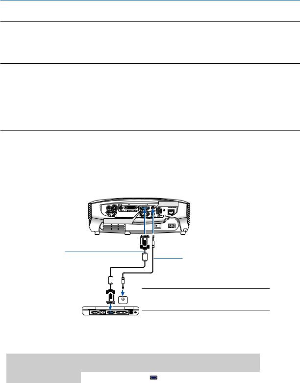
Connecting Your PC or Macintosh Computer
NOTE: Signals supported by Plug & Play (DDC2)
|
|
INPUT |
|
|
Model |
ANALOG IN-1 |
DIGITAL IN / ANALOG IN-2 |
|
|
|
analog |
analog |
digital |
|
LV-7375/LV-7370/LV-7275 |
Yes |
No |
Yes |
|
LV-8300 |
Yes |
Yes |
Yes |
|
|
|
|
|
|
AUDIO IN
ANALOG IN-1
VGA cable (supplied)
To mini D-Sub 15-pin connector on the projector. It is recommended that you use a commercially available distribution amplifier if connecting a signal cable longer than the cable supplied.
Audio cable (not supplied)
 PHONE
PHONE
NOTE: For older Macintosh, use a commercially available pin adapter (not supplied) to connect to your Mac’s video port.
IBM VGA or Compatibles (Notebook type) or Macintosh (Notebook type)
• Select the input name for its appropriate input connector after turning on the projector.
Input connector |
Use the INPUT button on the projector cabinet or the remote |
|
control to select the appropriate input from the menu. |
||
|
||
|
|
|
ANALOG IN-1 |
Computer 1 |
|
|
|
14
2. Installation and Connections
NOTE: Use an audio cable without a built-in resistor. Using an audio cable with a built-in resistor turns down the sound.
NOTE: An image may not be displayed correctly when a Video or S-Video source is played back via a commercially available scan converter.
This is because the projector will process a video signal as a computer signal at the default setting. In that case, do the following.
*When an image is displayed with the lower and upper black portion of the screen or a dark image is not displayed correctly: Project an image to fill the screen and then press the AUTO PC button on the remote control or the projector cabinet.
15
2. Installation and Connections
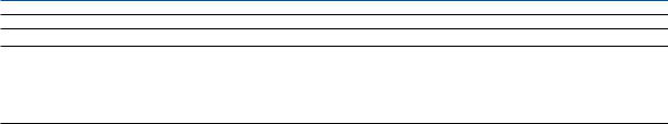
When Viewing a DVI Digital Signal
To project a DVI digital signal, be sure to connect the PC and the projector using a DVI cable (not supplied) before turning on your PC or projector. Turn on the projector first and select Computer 2 (Digital) from the source menu before turning on your PC.
Failure to do so may not activate the digital output of the graphics card resulting in no picture being displayed. Should this happen, restart your PC.
Do not disconnect the DVI cable while the projector is running. If the signal cable has been disconnected and then re-connected, an image may not be correctly displayed. Should this happen, restart your PC.
NOTE:
•Use a DVI cable or the one compliant with the DDWG (Digital Display Working Group) DVI (Digital Visual Interface) revision 1.0 standard. The DVI cable should be within 5 m (196) long. Both single and dual types of DVI cable can be used.
•The DVI (DIGITAL) connector accepts VGA (640x480), SVGA (800x600), 1152x864, XGA (1024x768), WXGA (1280x800 @ up to 60Hz), and SXGA (1280x1024 @ up to 60Hz).
Audio cable (not supplied)
AUDIO IN
 PHONE
PHONE
DVI cable (not supplied)
DIGITAL IN/
ANALOG IN-2
IBM PC or Compatibles (Desktop type) or Macintosh (Desktop type)
•Select the input name for its appropriate input connector after turning on the projector.
Input connector |
Use the INPUT button on the projector cabinet or the remote |
|
control to select the appropriate input from the menu. |
||
|
||
|
|
|
DIGITAL IN / |
Computer 2 (Digital) |
|
ANALOG IN-2 |
||
|
||
|
|
16
2. Installation and Connections
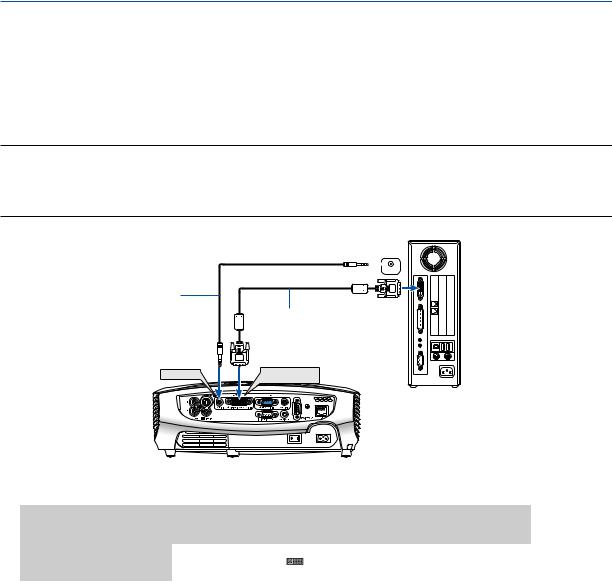
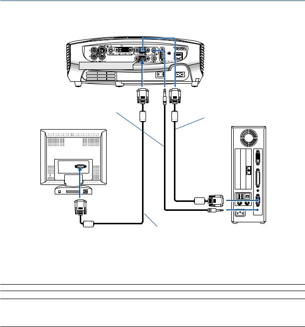
Using Two Analog Computer Inputs Simultaneously
If you need to use two analog inputs simultaneously, connect a VGA cable as shown below.
DIGITAL IN / |
ANALOG IN-1 |
ANALOG IN-2 |
|
DVI to VGA adapter 


(supplied)
VGA cable |
VGA cable |
(not supplied) |
|
|
(supplied) |
IBM PC or Compatibles (Desktop type) or Macintosh (Desktop type)
IBM VGA or Compatibles (Notebook type) or Macintosh (Notebook type)
NOTE: When the DVI to VGA adapter is not to be used for an extended period of time, remove it from the projector. Failure to do so may cause damage to the connector of the projector.
• Select the input name for its appropriate input connector after turning on the projector.
Input connector |
Use the INPUT button on the projector cabinet or the remote |
|
control to select the appropriate input from the menu. |
||
|
||
|
|
|
ANALOG IN-1 |
Computer 1 |
|
|
|
|
DIGITAL IN / |
Computer 2 (Analog) |
|
ANALOG IN-2 |
||
|
||
|
|
17
2. Installation and Connections
Connecting an External Monitor

 MONITOR OUT
Audio cable (not supplied)
VGA cable (supplied)
VGA cable (not supplied)
You can connect a separate, external monitor to your projector to simultaneously view on a monitor the RGB analog image you're projecting.
NOTE: Daisy chain connection is not possible.
NOTE:
•The signal from the DIGITAL IN/ANALOG IN-2 connector cannot be output from the MONITOR OUT connector.
•When audio equipment is connected, the projector speaker is disabled.
•Use an audio cable without a built-in resistor. Using an audio cable with a built-in resistor turns down the sound.
18
2. Installation and Connections
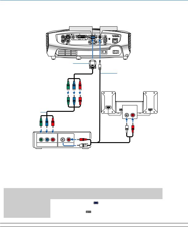
Connecting Your Audio-Video Equipment with Component Output
Use audio equipment for stereo sound.
ANALOG IN-1 |
AUDIO IN |
Optional 15-pin - to - RCA (female)
3 cable (LV-CA32)
Component video RCA 3 cable (not supplied)
L R
Component  OUT
OUT
Audio cable (not supplied)
AUDIO IN
L R
A component signal will be automatically displayed. If not, from the menu, select [Setup] → [Options(1)] → [Input signal select] or [Computer 2 (Analog)] → [Computer 1], and then select [COMPONENT].
• Select the input name for its appropriate input connector after turning on the projector.
Input connector |
Use the INPUT button on the projector cabinet or the remote |
|
control to select the appropriate input from the menu. |
||
|
||
|
|
|
ANALOG IN-1 |
Computer 1 |
|
|
|
|
DIGITAL IN / |
Computer 2 (Analog) |
|
ANALOG IN-2 |
||
|
||
|
|
NOTE: Refer to your DVD player’s owner’s manual for more information about your DVD player’s video output requirements.
19
2. Installation and Connections
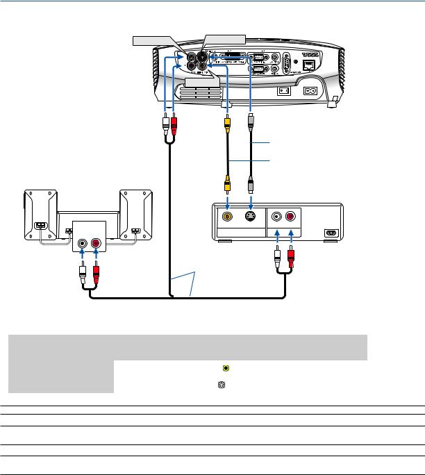
Connecting Your Audio-Video Equipment with Video/S-Video Output
AUDIO IN |
S-VIDEO IN |
VIDEO IN
S-Video cable (not supplied)
Video cable (not supplied)
AUDIO IN |
VIDEO S-VIDEO |
L R |
L R |
VIDEO OUT |
|
Audio cable (not supplied)
• Select the input name for its appropriate input connector after turning on the projector.
Input connector |
Use the INPUT button on the projector cabinet or the remote |
|
control to select the appropriate input from the menu. |
||
|
||
|
|
|
VIDEO IN |
VIDEO |
|
|
|
|
S-VIDEO IN |
S-VIDEO |
|
|
|
NOTE: The AUDIO IN L/MONO and R jacks (RCA) are shared between the Video and S-Video inputs.
NOTE: Refer to your audio-video equipment's owner's manual for more information about your equipment's video output requirements.
NOTE: An image may not be displayed correctly when a Video or S-Video source is played back in fast-forward or fast-rewind via a scan converter.
20
Loading...