


 Loading...
Service Manual
MF4600 Series
Feb 26 2007
Application
This manual has been issued by Canon Inc. for qualified persons to learn technical theory, installation, maintenance, and repair of products. This manual covers all localities where the products are sold. For this reason, there may be information in this manual that does not apply to your locality.
Corrections
This manual may contain technical inaccuracies or typographical errors due to improvements or changes in products. When changes occur in applicable products or in the contents of this manual, Canon will release technical information as the need arises. In the event of major changes in the contents of this manual over a long or short period, Canon will issue a new edition of this manual.
The following paragraph does not apply to any countries where such provisions are inconsistent with local law.
Trademarks
The product names and company names used in this manual are the registered trademarks of the individual companies.
Copyright
This manual is copyrighted with all rights reserved. Under the copyright laws, this manual may not be copied, reproduced or translated into another language, in whole or in part, without the written consent of Canon Inc.
COPYRIGHT © 2001 CANON INC.
Printed in Japan
Caution
Use of this manual should be strictly supervised to avoid disclosure of confidential information.
Introduction
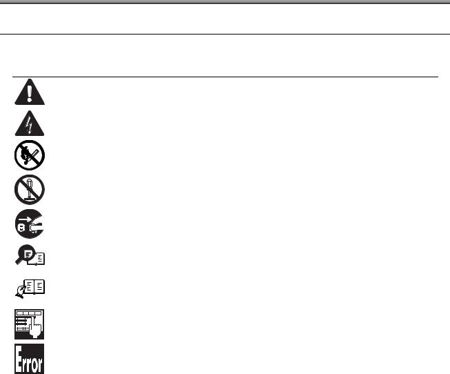
Symbols Used
This documentation uses the following symbols to indicate special information:
Symbol Description
Indicates an item of a non-specific nature, possibly classified as Note, Caution, or Warning.
Indicates an item requiring care to avoid electric shocks.
Indicates an item requiring care to avoid combustion (fire).
Indicates an item prohibiting disassembly to avoid electric shocks or problems.
Indicates an item requiring disconnection of the power plug from the electric outlet.
Indicates an item intended to provide notes assisting the understanding of the topic in question.
Memo
Indicates an item of reference assisting the understanding of the topic in question.
REF.
Provides a description of a service mode.
Provides a description of the nature of an error indication.

Introduction
The following rules apply throughout this Service Manual:
1.Each chapter contains sections explaining the purpose of specific functions and the relationship between electrical and mechanical systems with reference to the timing of operation.
In the diagrams,  represents the path of mechanical drive; where a signal name accompanies the symbol , the arrow
  indicates the
direction of the electric signal.
The expression "turn on the power" means flipping on the power switch, closing the front door, and closing the delivery unit door, which results in supplying the machine with power.
2.In the digital circuits, '1'is used to indicate that the voltage level of a given signal is "High", while '0' is used to indicate "Low".(The voltage value, however, differs from circuit to circuit.) In addition, the asterisk (*) as in "DRMD*" indicates that the DRMD signal goes on when '0'.
In practically all cases, the internal mechanisms of a microprocessor cannot be checked in the field. Therefore, the operations of the microprocessors used in the machines are not discussed: they are explained in terms of from sensors to the input of the DC controller PCB and from the output of the DC controller PCB to the loads.
The descriptions in this Service Manual are subject to change without notice for product improvement or other purposes, and major changes will be communicated in the form of Service Information bulletins.
All service persons are expected to have a good understanding of the contents of this Service Manual and all relevant Service Information bulletins and be able to identify and isolate faults in the machine."

Contents
Contents
Chapter 1 Introduction |
|
1.1 Product Specifications ................................................................................................................................ |
1- 1 |
1.1.1 Names of Parts........................................................................................................................................................ |
1- 1 |
1.1.1.1 External View ........................................................................................................................................................................... |
1- 1 |
1.1.1.2 Section View (Host Machine)................................................................................................................................................... |
1- 3 |
1.1.1.3 Section View (ADF).................................................................................................................................................................. |
1- 3 |
1.1.1.4 Control panel............................................................................................................................................................................ |
1- 4 |
1.1.2 Safety ...................................................................................................................................................................... |
1- 5 |
1.1.2.1 Safety of the Host Machine's Laser Mechanism ...................................................................................................................... |
1- 5 |
1.1.2.2 CDRH Regulations................................................................................................................................................................... |
1- 5 |
1.1.2.3 Handling of the Laser Assembly .............................................................................................................................................. |
1- 6 |
1.1.2.4 Safety of the Toner .................................................................................................................................................................. |
1- 6 |
1.1.2.5 Fire Attention............................................................................................................................................................................ |
1- 6 |
1.1.2.6 Points no Note when Replacing / Disposing the Lithium Battery ............................................................................................. |
1- 6 |
1.1.3 Product Specifications ............................................................................................................................................. |
1- 7 |
1.1.3.1 Host Machine Specifications.................................................................................................................................................... |
1- 7 |
1.1.3.2 ADF Specifications................................................................................................................................................................... |
1- 8 |
1.1.3.3 FAX Specifications................................................................................................................................................................... |
1- 8 |
Chapter 2 Basic Operation |
|
2.1 Construction ............................................................................................................................................... |
2- 1 |
2.1.1 Function Configuration ............................................................................................................................................ |
2- 1 |
2.2 Basic Sequence.......................................................................................................................................... |
2- 1 |
2.2.1 Basic Operation Sequence...................................................................................................................................... |
2- 1 |
Chapter 3 Original Exposure System |
|
3.1 Basic Constraction...................................................................................................................................... |
3- 1 |
3.1.1 Specifications / Control / Function List .................................................................................................................... |
3- 1 |
3.1.2 Major Components .................................................................................................................................................. |
3- 1 |
3.2 Various Control........................................................................................................................................... |
3- 2 |
3.2.1 Dirt Sensor Control .................................................................................................................................................. |
3- 2 |
3.2.1.1 Outline...................................................................................................................................................................................... |
3- 2 |
3.3 Parts Replacement Procedure ................................................................................................................... |
3- 4 |
3.3.1 Scanner Unit............................................................................................................................................................ |
3- 4 |
3.3.1.1 Preparation for Removing the Control Panel Assembly........................................................................................................... |
3- 4 |
3.3.1.2 Removing the Control Panel Assembly ................................................................................................................................... |
3- 4 |
3.3.2 Book Motor .............................................................................................................................................................. |
3- 4 |
3.3.2.1 Preparation for Removing the Flat Bed Motor ......................................................................................................................... |
3- 4 |
3.3.2.2 Removing the Flat Bed Motor .................................................................................................................................................. |
3- 4 |
3.3.3 Contact Sensor........................................................................................................................................................ |
3- 5 |
3.3.3.1 Removing the Contact Sensor ................................................................................................................................................. |
3- 5 |
Chapter 4 Original Feeding System |
|
4.1 Basic Operation .......................................................................................................................................... |
4- 1 |
4.1.1 Basic Operation ....................................................................................................................................................... |
4- 1 |
4.1.2 Original Detection .................................................................................................................................................... |
4- 2 |
4.2 Detection Jams........................................................................................................................................... |
4- 2 |
4.2.1 Jam Detection.......................................................................................................................................................... |
4- 2 |
4.3 ADF ............................................................................................................................................................ |
4- 3 |

Contents
4.3.1 Pick-up Roller........................................................................................................................................................... |
4- 3 |
4.3.1.1 Removing the ADF Pickup Roller ............................................................................................................................................ |
4- 3 |
4.3.2 ADF Motor................................................................................................................................................................ |
4- 3 |
4.3.2.1 Preparation for Removing the ADF Motor................................................................................................................................ |
4- 3 |
4.3.2.2 Removing the ADF Motor ........................................................................................................................................................ |
4- 3 |
4.3.3 Separation Pad ........................................................................................................................................................ |
4- 4 |
4.3.3.1 Removing the Separation Pad ................................................................................................................................................. |
4- 4 |
Chapter 5 Laser Exposure |
|
|
5.1 |
Overview/Configuration .............................................................................................................................. |
5- 1 |
5.1.1 Overview .................................................................................................................................................................. |
5- 1 |
|
5.2 |
Controlling the Laser Activation Timing...................................................................................................... |
5- 2 |
5.2.1 Laser ON / OFF Control........................................................................................................................................... |
5- 2 |
|
5.3 |
Controlling the Intensity of Laser Light ....................................................................................................... |
5- 2 |
5.3.1 Auto Photoelectric Current Control (APC) ............................................................................................................... |
5- 2 |
|
5.4 |
Controlling the Laser Scanner Motor.......................................................................................................... |
5- 2 |
5.4.1 Overview .................................................................................................................................................................. |
5- 2 |
|
5.4.2 Scanner Motor Speed Control ................................................................................................................................. |
5- 3 |
|
5.4.3 Detection of Fault of the Scanner Motor .................................................................................................................. |
5- 3 |
|
5.5 |
Parts Replacement Procedure ................................................................................................................... |
5- 4 |
5.5.1 Laser/Scanner Unit .................................................................................................................................................. |
5- 4 |
|
|
5.5.1.1 Preparation for Removing the Laser Scanner Unit .................................................................................................................. |
5- 4 |
|
5.5.1.2 Removing the Laser Scanner Unit ........................................................................................................................................... |
5- 4 |
Chapter 6 Image Formation |
|
|
6.1 |
Overview/Configuration .............................................................................................................................. |
6- 1 |
6.1.1 Configuration............................................................................................................................................................ |
6- 1 |
|
6.1.2 Print Process............................................................................................................................................................ |
6- 1 |
|
6.2 |
Driving and Controlling the High-Voltage System ...................................................................................... |
6- 3 |
6.2.1 Generation of Transfer Charging Bias ..................................................................................................................... |
6- 3 |
|
6.3 |
Toner Cartridge .......................................................................................................................................... |
6- 3 |
6.3.1 Toner Level Detection.............................................................................................................................................. |
6- 3 |
|
6.4 |
Parts Replacement Procedure ................................................................................................................... |
6- 4 |
6.4.1 Transfer Charging Roller.......................................................................................................................................... |
6- 4 |
|
|
6.4.1.1 Removing the Transfer Charging Roller .................................................................................................................................. |
6- 4 |
Chapter 7 Pickup and Feed System |
|
|
7.1 |
Overview/Configuration .............................................................................................................................. |
7- 1 |
7.1.1 Overview .................................................................................................................................................................. |
7- 1 |
|
7.2 |
Other Control.............................................................................................................................................. |
7- 1 |
7.2.1 Overview .................................................................................................................................................................. |
7- 1 |
|
7.3 |
Detection Jams........................................................................................................................................... |
7- 3 |
7.3.1 Jam Detection Outline.............................................................................................................................................. |
7- 3 |
|
|
7.3.1.1 Overview .................................................................................................................................................................................. |
7- 3 |
7.3.2 Delay Jams .............................................................................................................................................................. |
7- 3 |
|
|
7.3.2.1 Pickup Delay Jam ................................................................................................................................................................... |
7- 3 |
|
7.3.2.2 Delivery Delay Jam .................................................................................................................................................................. |
7- 3 |
7.3.3 Stationary Jams ....................................................................................................................................................... |
7- 3 |
|
|
7.3.3.1 Pickup Stationary Jam ............................................................................................................................................................ |
7- 3 |
|
7.3.3.2 Delivery Stationary Jam .......................................................................................................................................................... |
7- 3 |
7.3.4 Other Jams .............................................................................................................................................................. |
7- 3 |
|
7.3.4.1 Door Open Jam ....................................................................................................................................................................... |
7- 3 |
7.3.4.2 Wrapping Jam ......................................................................................................................................................................... |
7- 3 |
7.3.4.3 Residual Jam at Startup .......................................................................................................................................................... |
7- 4 |
|
Contents |
|
|
|
|
7.4 Duplex Unit ................................................................................................................................................. |
7- 5 |
7.4.1 Overview.................................................................................................................................................................. |
7- 5 |
7.5 Parts Replacement Procedure ................................................................................................................... |
7- 6 |
7.5.1 Main Motor............................................................................................................................................................... |
7- 6 |
7.5.1.1 Preparation for Removing Main Motor ..................................................................................................................................... |
7- 6 |
7.5.1.2 Removing Main Motor.............................................................................................................................................................. |
7- 6 |
7.5.2 Separation Pad........................................................................................................................................................ |
7- 6 |
7.5.2.1 Preparation for Removing Separation Pad .............................................................................................................................. |
7- 6 |
7.5.2.2 Removing Separation Pad ....................................................................................................................................................... |
7- 6 |
7.5.3 Pickup Roller ........................................................................................................................................................... |
7- 6 |
7.5.3.1 Removing Pickup Roller........................................................................................................................................................... |
7- 6 |
Chapter 8 Fixing System |
|
8.1 Overview/Configuration .............................................................................................................................. |
8- 1 |
8.1.1 Specification/Control/Function List ......................................................................................................................... |
8- 1 |
8.1.2 Overview.................................................................................................................................................................. |
8- 1 |
8.2 Various Control Mechanisms...................................................................................................................... |
8- 3 |
8.2.1 Controlling the Temperature of the Fixing Unit........................................................................................................ |
8- 3 |
8.2.1.1 Fixing Temperature Control .................................................................................................................................................... |
8- 3 |
8.3 Protection Function..................................................................................................................................... |
8- 4 |
8.3.1 Protection Function ................................................................................................................................................. |
8- 4 |
8.4 Parts Replacement Procedure ................................................................................................................... |
8- 6 |
8.4.1 Fixing Unit................................................................................................................................................................ |
8- 6 |
8.4.1.1 Preparation for Removing Fixing Assembly............................................................................................................................. |
8- 6 |
8.4.1.2 Removing Fixing Assembly...................................................................................................................................................... |
8- 6 |
8.4.2 Fixing Film Unit........................................................................................................................................................ |
8- 6 |
8.4.2.1 Preparation for Removing Fixing Film Unit .............................................................................................................................. |
8- 6 |
8.4.2.2 Removing Fixing Film Unit ....................................................................................................................................................... |
8- 6 |
Chapter 9 External and Controls |
|
9.1 Control Panel.............................................................................................................................................. |
9- 1 |
9.1.1 Outline ..................................................................................................................................................................... |
9- 1 |
9.2 Power Supply ............................................................................................................................................. |
9- 1 |
9.2.1 Protection Function.................................................................................................................................................. |
9- 1 |
9.2.1.1 Protecting Function .................................................................................................................................................................. |
9- 1 |
9.3 Parts Replacement Procedure ................................................................................................................... |
9- 2 |
9.3.1 Front Cover.............................................................................................................................................................. |
9- 2 |
9.3.1.1 Removing the Front Cover....................................................................................................................................................... |
9- 2 |
9.3.2 Rear Cover .............................................................................................................................................................. |
9- 2 |
9.3.2.1 Preparation for Removing the Rear Cover............................................................................................................................... |
9- 2 |
9.3.2.2 Removing the Rear Cover ....................................................................................................................................................... |
9- 2 |
9.3.3 Right Cover.............................................................................................................................................................. |
9- 2 |
9.3.3.1 Removing the Right Cover....................................................................................................................................................... |
9- 2 |
9.3.4 Left Cover ................................................................................................................................................................ |
9- 2 |
9.3.4.1 Removing the Left Cover ......................................................................................................................................................... |
9- 2 |
9.3.5 Upper Cover ............................................................................................................................................................ |
9- 3 |
9.3.5.1 Preparation for Removing the Upper Cover............................................................................................................................. |
9- 3 |
9.3.5.2 Removing the Upper Cover ..................................................................................................................................................... |
9- 3 |
9.3.6 Cartridge Cover ....................................................................................................................................................... |
9- 3 |
9.3.6.1 Preparation for Removing the Printer Cover............................................................................................................................ |
9- 3 |
9.3.6.2 Removing the Printer Cover..................................................................................................................................................... |
9- 3 |
9.3.7 Operation Panel Unit ............................................................................................................................................... |
9- 4 |
9.3.7.1 Removing the Control Panel Unit............................................................................................................................................. |
9- 4 |
9.3.8 SCNT Board ............................................................................................................................................................ |
9- 4 |
9.3.8.1 |
Preparation for Removing the SCNT Board............................................................................................................................. |
9- 4 |
9.3.8.2 |
Removing the SCNT Board ..................................................................................................................................................... |
9- 4 |

Contents
9.3.8.3 Actions At Replacing the SCNT Board .................................................................................................................................... |
9- 5 |
9.3.9 DCNT Board ............................................................................................................................................................ |
9- 5 |
9.3.9.1 Preparation for Removing the DCNT Board ............................................................................................................................ |
9- 5 |
9.3.9.2 Removing the DCNT Board ..................................................................................................................................................... |
9- 5 |
9.3.10 Analog Processor PCB .......................................................................................................................................... |
9- 6 |
9.3.10.1 Preparation for Removing the Analog processor PCB........................................................................................................... |
9- 6 |
9.3.10.2 Removing the Analog processor PCB.................................................................................................................................... |
9- 6 |
9.3.11 NCU Board............................................................................................................................................................. |
9- 6 |
9.3.11.1 Preparation for Removing the NCU Board............................................................................................................................. |
9- 6 |
9.3.11.2 Removing the NCU Board...................................................................................................................................................... |
9- 6 |
9.3.12 Power Supply PCB................................................................................................................................................. |
9- 7 |
9.3.12.1 Preparation for Removing the Power Supply Board .............................................................................................................. |
9- 7 |
9.3.12.2 Removing the Power Supply Board ....................................................................................................................................... |
9- 7 |
9.3.13 High-voitage Power Supply PCB ........................................................................................................................... |
9- 7 |
9.3.13.1 Preparation for Removing the High Voltage Power Supply Board......................................................................................... |
9- 7 |
9.3.13.2 Removing the High Voltage Power Supply Board.................................................................................................................. |
9- 7 |
9.3.14 Motor Driver PCB ................................................................................................................................................... |
9- 7 |
9.3.14.1 Preparation for Removing the Motor driver PCB.................................................................................................................... |
9- 7 |
9.3.14.2 Removing the Motor driver PCB ............................................................................................................................................ |
9- 8 |
Chapter 10 Maintenance and Inspection |
|
|
10.1 |
Periodically Replaced Parts.................................................................................................................... |
10- 1 |
10.1.1 Periodically Replaced Parts ................................................................................................................................. |
10- 1 |
|
10.2 |
Consumables.......................................................................................................................................... |
10- 1 |
10.2.1 Consumable ......................................................................................................................................................... |
10- 1 |
|
10.3 |
Periodical Service................................................................................................................................... |
10- 1 |
10.3.1 Periodically Service Items .................................................................................................................................... |
10- 1 |
|
10.4 |
Cleaning ................................................................................................................................................. |
10- 1 |
10.4.1 Cleaning Items ..................................................................................................................................................... |
10- 1 |
|
10.4.2 Cleaning Method (External Covers) ..................................................................................................................... |
10- 1 |
|
10.4.3 Cleaning Method (Reader Unit) ........................................................................................................................... |
10- 2 |
|
10.4.4 Cleaning Method (Pressure Roller)...................................................................................................................... |
10- 2 |
|
Chapter 11 Measurement and Adjustments |
|
|
11.1 |
Scanning System.................................................................................................................................... |
11- 1 |
11.1.1 Procedure after Replacing the CIS ...................................................................................................................... |
11- 1 |
|
11.1.2 Procedure after Replacing the Copyboard Glass................................................................................................. |
11- 1 |
|
11.2 |
Electrical Adjustments ............................................................................................................................ |
11- 1 |
11.2.1 Procedure after Replacing the SCNT board ........................................................................................................ |
11- 1 |
|
Chapter 12 Correcting Faulty Images |
|
|
12.1 |
Outline of Electrical Components ........................................................................................................... |
12- 1 |
12.1.1 Clutch/Solenoid/Motor/Fan................................................................................................................................... |
12- 1 |
|
|
12.1.1.1 List of Solenoids/Motors....................................................................................................................................................... |
12- 1 |
12.1.2 Sensor.................................................................................................................................................................. |
12- 2 |
|
|
12.1.2.1 List of Sensors ..................................................................................................................................................................... |
12- 2 |
12.1.3 PCBs .................................................................................................................................................................... |
12- 3 |
|
|
12.1.3.1 List of PCBs ......................................................................................................................................................................... |
12- 3 |
Chapter 13 Error Code |
|
|
13.1 |
Error Code .............................................................................................................................................. |
13- 1 |
13.1.1 List of Error Codes ............................................................................................................................................... |
13- 1 |
|
13.2 |
Fax Error Codes ..................................................................................................................................... |
13- 2 |
13.2.1 Outline.................................................................................................................................................................. |
13- 2 |
|
Contents |
|
|
|
|
13.2.1.1 Error Code Outline ............................................................................................................................................................... |
13- 2 |
13.2.2 User Error Code................................................................................................................................................... |
13- 3 |
13.2.2.1 User Error Code ................................................................................................................................................................... |
13- 3 |
13.2.3 Service Error Code .............................................................................................................................................. |
13- 3 |
13.2.3.1 Service Error Code............................................................................................................................................................... |
13- 3 |
Chapter 14 Service Mode |
|
14.1 Outline .................................................................................................................................................... |
14- 1 |
14.1.1 Outline of Service Mode ...................................................................................................................................... |
14- 1 |
14.1.2 Using the Mode.................................................................................................................................................... |
14- 1 |
14.2 Default Settings ...................................................................................................................................... |
14- 2 |
14.2.1 Service Mode Menus ........................................................................................................................................... |
14- 2 |
14.3 Service Soft Switch Settings (SSSW)..................................................................................................... |
14- 5 |
14.3.1 Outline ................................................................................................................................................................. |
14- 5 |
14.3.1.1 Bit Switch Composition ........................................................................................................................................................ |
14- 5 |
14.3.2 SSSW-SW01: ...................................................................................................................................................... |
14- 6 |
14.3.2.1 List of Functions ................................................................................................................................................................... |
14- 6 |
14.3.2.2 Detailed Discussions of Bit 0................................................................................................................................................ |
14- 6 |
14.3.3 SSSW-SW03 ....................................................................................................................................................... |
14- 6 |
14.3.3.1 List of Functions ................................................................................................................................................................... |
14- 6 |
14.3.3.2 Detailed Discussions of Bit 7................................................................................................................................................ |
14- 6 |
14.3.4 SSSW-SW04 ....................................................................................................................................................... |
14- 6 |
14.3.4.1 List of Functions ................................................................................................................................................................... |
14- 6 |
14.3.4.2 Detailed Discussions of Bit 2................................................................................................................................................ |
14- 7 |
14.3.4.3 Detailed Discussions of Bit 3................................................................................................................................................ |
14- 7 |
14.3.4.4 Detailed Discussions of Bit 4................................................................................................................................................ |
14- 7 |
14.3.4.5 Detailed Discussions of Bit 6................................................................................................................................................ |
14- 7 |
14.3.4.6 Detailed Discussions of Bit 7................................................................................................................................................ |
14- 7 |
14.3.5 SSSW-SW05 ....................................................................................................................................................... |
14- 7 |
14.3.5.1 List of Functions ................................................................................................................................................................... |
14- 7 |
14.3.5.2 Detailed Discussions of Bit 1................................................................................................................................................ |
14- 7 |
14.3.5.3 Detailed Discussions of Bit 2................................................................................................................................................ |
14- 7 |
14.3.6 SSSW-SW12 ....................................................................................................................................................... |
14- 8 |
14.3.6.1 List of Functions ................................................................................................................................................................... |
14- 8 |
14.3.7 SSSW-SW13 ....................................................................................................................................................... |
14- 8 |
14.3.7.1 List of Functions ................................................................................................................................................................... |
14- 8 |
14.3.7.2 Detailed Discussions of Bit 2................................................................................................................................................ |
14- 8 |
14.3.8 SSSW-SW14 ....................................................................................................................................................... |
14- 8 |
14.3.8.1 List of Functions ................................................................................................................................................................... |
14- 8 |
14.3.8.2 Detailed Discussions of Bit 2................................................................................................................................................ |
14- 9 |
14.3.8.3 Detailed Discussions of Bit 4................................................................................................................................................ |
14- 9 |
14.3.9 SSSW-SW18 ....................................................................................................................................................... |
14- 9 |
14.3.9.1 List of Functions ................................................................................................................................................................... |
14- 9 |
14.3.9.2 Detailed Discussions of Bit 0................................................................................................................................................ |
14- 9 |
14.3.9.3 Detailed Discussions of Bit 1................................................................................................................................................ |
14- 9 |
14.3.10 SSSW-SW25 ..................................................................................................................................................... |
14- 9 |
14.3.10.1 List of Functions ................................................................................................................................................................. |
14- 9 |
14.3.10.2 Detailed Discussions of Bit 0.............................................................................................................................................. |
14- 9 |
14.3.10.3 Detailed Discussions of Bit 2............................................................................................................................................ |
1410 |
14.3.11 SSSW-SW28 ................................................................................................................................................... |
1410 |
14.3.11.1 List of Functions ............................................................................................................................................................... |
1410 |
14.3.11.2 Detailed Discussions of Bit 0............................................................................................................................................ |
1410 |
14.3.11.3 Detailed Discussions of Bit 1............................................................................................................................................ |
1410 |
14.3.11.4 Detailed Discussions of Bit 2............................................................................................................................................ |
1410 |
14.3.11.5 Detailed Discussions of Bit 3............................................................................................................................................ |
1410 |
14.3.11.6 Detailed Discussions of Bit 4............................................................................................................................................ |
1410 |
14.3.11.7 Detailed Discussions of Bit 5............................................................................................................................................ |
1410 |
14.3.12 SSSW-SW30 ................................................................................................................................................... |
1410 |

Contents
14.3.12.1 List of Functions ............................................................................................................................................................... |
1410 |
14.3.12.2 Detailed Discussions of Bit 5............................................................................................................................................ |
1410 |
14.4 Menu Switch Settings (MENU) ............................................................................................................. |
1411 |
14.4.1 Menu Switch Composition.................................................................................................................................. |
1411 |
14.4.2 <No.005 NL equalizer> ...................................................................................................................................... |
1411 |
14.4.3 <No.006 telephone line monitor> ....................................................................................................................... |
1411 |
14.4.4 <No.007 ATT transmission level> ...................................................................................................................... |
1411 |
14.4.5 <No.008 V.34 modulation speed upper limit> .................................................................................................... |
1411 |
14.4.6 <No.009 V.34 data speed upper limit>............................................................................................................... |
1411 |
14.4.7 <No.010 Frequency of the pseudo CI signal>.................................................................................................... |
1411 |
14.5 Numeric Parameter Settings (NUMERIC Param.)................................................................................ |
1411 |
14.5.1 Numerical Parameter Composition .................................................................................................................... |
1411 |
14.5.2 <002: RTN transmission condition (1)><003: RTN transmission condition (2)><004: RTN transmission condition (3)>
1412 |
|
|
14.5.3 <005: NCC pause length (pre-ID code)> ........................................................................................................... |
1412 |
|
14.5.4 <006: NCC pause length (post-ID code)>.......................................................................................................... |
1412 |
|
14.5.5 <010: line connection identification length> ....................................................................................................... |
1412 |
|
14.5.6 <011: T.30 |
T1 timer (for reception)> .................................................................................................................. |
1413 |
14.5.7 <013: T.30 |
EOL timer>....................................................................................................................................... |
1413 |
14.5.8 <016: time length to first response at time of fax/tel switchover> ...................................................................... |
1413 |
|
14.5.9 <017: pseudo RBT signal pattern ON time length><018: pseudo RBT signal pattern OFF time length (short)><019:
pseudo RBT signal pattern OFF time length (long)> ............................................................................................... |
1413 |
14.5.10 <020: pseudo CI signal pattern ON time length><021: pseudo CI signal pattern OFF time length (short)><022:
pseudo CI signal pattern OFF time length (long)> ................................................................................................... |
1413 |
14.5.11 <023: CNG detention level for fax/tel switchover> ........................................................................................... |
1413 |
14.5.12 <024: pseudo RBT transmission level at time of fax/tel switchover> ............................................................... |
1413 |
14.5.13 <025: Answering machine connection function signal detection time> ............................................................ |
1413 |
14.5.14 <027: V.21 low-speed flag preamble identification length>.............................................................................. |
1413 |
14.5.15 <056 - 061: Count type select > ....................................................................................................................... |
1413 |
14.6 Scanner Function Settings (SCANNER)............................................................................................... |
1416 |
14.6.1 Numeric Parameter Functional configuration..................................................................................................... |
1416 |
14.6.2 <031Vertical scan start position adjustment> .................................................................................................... |
1417 |
14.6.3 <033Vertical scan magnification correction> ..................................................................................................... |
1417 |
14.6.4 <035: - 036:Reader motor speed change> ........................................................................................................ |
1417 |
14.6.5 <041: Vertical scan start position adjustment (when scanning on a document fed from ADF)>........................ |
1417 |
14.6.6 <047: Vertical scan magnification correction (when scanning on a document fed from ADF)>......................... |
1417 |
14.6.7 <048: Horizontal scan magnification correction (when scanning on a document fed from ADF)>..................... |
1417 |
14.7 Printer Function Settings (PRINTER) ................................................................................................... |
1417 |
14.7.1 Service Soft Switch Settings (SSSW) ................................................................................................................ |
1417 |
14.7.1.1 SSSW-SW15...................................................................................................................................................................... |
1417 |
14.7.2 Numeric Parameter Settings (NUMERIC Param.) ............................................................................................. |
1417 |
14.7.2.1 <034: Left-end registration adjustment (malti-purpose tray)> ............................................................................................ |
1417 |
14.7.2.2 <035: Left-end registration adjustment (cassette)>............................................................................................................ |
1418 |
14.7.2.3 <039: Left-end registration adjustment (duplex unit)>........................................................................................................ |
1418 |
14.7.2.4 <053: Margin adjustment at the leading edge of the copy> ............................................................................................... |
1418 |
14.7.2.5 <054: Margin adjustment at the trailing edge of the copy> ................................................................................................ |
1418 |
14.7.2.6 <055: Margin adjustment at the right edge of the copy>.................................................................................................... |
1418 |
14.7.2.7 <056: Margin adjustment at the left edge of the copy> ...................................................................................................... |
1418 |
14.8 Setting of System Functions (SYSTEM)............................................................................................... |
1418 |
14.8.1 Bit Switch Settings ............................................................................................................................................. |
1418 |
14.9 Counter Indication (COUNTER) ........................................................................................................... |
1418 |
14.9.1 Counters............................................................................................................................................................. |
1418 |
14.9.2 Clearing Counters .............................................................................................................................................. |
1419 |
14.10 Report Output (REPORT)................................................................................................................... |
1420 |
14.10.1 |
Report Output................................................................................................................................................... |
1420 |
14.10.2 |
System Data List .............................................................................................................................................. |
1420 |
|
Contents |
|
|
|
|
14.10.3 System Dump List............................................................................................................................................ |
1421 |
14.10.4 Counter List...................................................................................................................................................... |
1422 |
14.10.5 Spec List .......................................................................................................................................................... |
1422 |
14.11 Data Initialization Mode (CLEAR) ....................................................................................................... |
1424 |
14.11.1 Clear ................................................................................................................................................................ |
1424 |
14.12 ROM Management (ROM).................................................................................................................. |
1424 |
14.12.1 ROM Display.................................................................................................................................................... |
1424 |
14.13 Test Mode (TEST) .............................................................................................................................. |
1424 |
14.13.1 Overview .......................................................................................................................................................... |
1424 |
14.13.1.1 Outline .............................................................................................................................................................................. |
1424 |
14.13.1.2 Test Mode Menu List ....................................................................................................................................................... |
1425 |
14.13.2 DRAM Test ...................................................................................................................................................... |
1426 |
14.13.2.1 D-RAM Test<(1) D-RAM TEST> ...................................................................................................................................... |
1426 |
14.13.3 Scan Test......................................................................................................................................................... |
1426 |
14.13.3.1 Scan Test ((2) SCAN TEST) ............................................................................................................................................ |
1426 |
14.13.4 Print Test.......................................................................................................................................................... |
1427 |
14.13.4.1 Print Test ((3) PRINT TEST) ............................................................................................................................................ |
1427 |
14.13.5 Modem Test ..................................................................................................................................................... |
1427 |
14.13.5.1 MODEM Test ((4) MODEM TEST)................................................................................................................................... |
1427 |
14.13.6 Faculty Test ..................................................................................................................................................... |
1429 |
14.13.6.1 FUNCTION TEST <(6) FUNCTION TEST> ..................................................................................................................... |
1429 |
14.13.7 Cleaning Mode................................................................................................................................................. |
1431 |
14.13.7.1 Roller cleaning mode ((0) ROLLER CLEAN) ................................................................................................................... |
1431 |
Chapter 15 Service Tools |
|
15.1 Service Tools .......................................................................................................................................... |
15- 1 |
15.1.1 Solvents / Lubricants Table ................................................................................................................................. |
15- 1 |

Chapter 1 Introduction

Contents
Contents
1.1 Product Specifications.................................................................................................................................................... |
1-1 |
1.1.1 Names of Parts ............................................................................................................................................................................. |
1-1 |
1.1.1.1 External View.................................................................................................................................................................................................. |
1-1 |
1.1.1.2 Section View (Host Machine)......................................................................................................................................................................... |
1-3 |
1.1.1.3 Section View (ADF) ....................................................................................................................................................................................... |
1-3 |
1.1.1.4 Control panel................................................................................................................................................................................................... |
1-4 |
1.1.2 Safety ........................................................................................................................................................................................... |
1-5 |
1.1.2.1 Safety of the Host Machine's Laser Mechanism ............................................................................................................................................. |
1-5 |
1.1.2.2 CDRH Regulations.......................................................................................................................................................................................... |
1-5 |
1.1.2.3 Handling of the Laser Assembly..................................................................................................................................................................... |
1-6 |
1.1.2.4 Safety of the Toner.......................................................................................................................................................................................... |
1-6 |
1.1.2.5 Fire Attention .................................................................................................................................................................................................. |
1-6 |
1.1.2.6 Points no Note when Replacing / Disposing the Lithium Battery .................................................................................................................. |
1-6 |
1.1.3 Product Specifications ................................................................................................................................................................. |
1-7 |
1.1.3.1 Host Machine Specifications........................................................................................................................................................................... |
1-7 |
1.1.3.2 ADF Specifications ......................................................................................................................................................................................... |
1-8 |
1.1.3.3 FAX Specifications ......................................................................................................................................................................................... |
1-8 |
Chapter 1
1.1 Product Specifications
1.1.1 Names of Parts
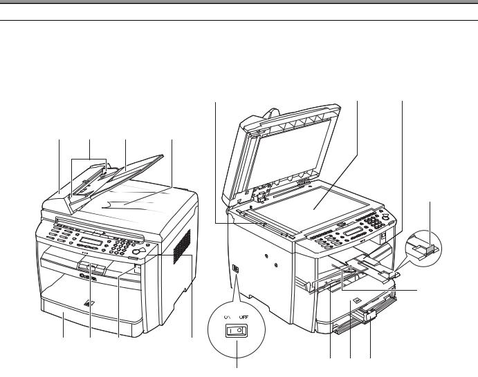
1.1.1.1 External View
i-SENSYS MF4690PL / i-SENSYS MF4660
Front View (Body)
[9] |
|
[10] |
|
[11] |
[1] |
|
[2] |
|
[3] |
|
[4] |
[12]
[13]
[8] |
[7] |
[6] |
[5] |
[16] [15] [14]
[17]
F-1-1
[1]ADF (Automatic Document Feeder)
[2]Slide Guides
[3]Document feeder tray
[4]Document delivery tray
[5]Operation panel
[6]USB memory port
[7]Output tray
[8]Paper cassette
[9]Scanning area
[10]Platen glass
[11]Output tray extension
[12]Paper stopper
[13]Slide guides for multi-purpose tray
[14]Paper guide rail
[15]Dust cover
[16]Multi-purpose tray
[17]Main power switch
1-1
Chapter 1
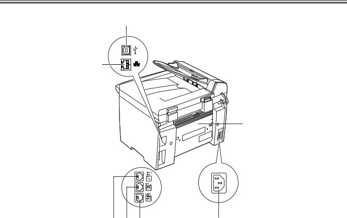
Rear View (Body)
[1]
[7]
[2]
[6] [5] [4] |
[3] |
|
F-1-2 |
|
T-1-1 |
[1] USB port |
[5] External device jack* |
[2] Rear cover |
[6] Handset jack* |
[3] Power socket |
[7] Ethernet port |
[4] Telephone line jack* |
* MF4690PL only |
1-2

Chapter 1
1.1.1.2 Section View (Host Machine) i-SENSYS MF4690PL / / i-SENSYS MF4660
[1] |
|
[2] |
|
|
[3] |
|
[4] |
|
||
|
|
|
|
|
|
|
|
|
|
|
|
|
|
|
|
|
|
|
|
|
|
|
|
|
|
|
|
|
|
|
|
|
[14]
[13]
[12]
[11]
|
[10] |
|
[9] |
|
[8] |
|
|
[7] |
|
[6] |
|
[5] |
|
|
|
|
|
|
|
F-1-3 |
|
|
|
|
|
[1] |
|
pressure roller |
|
|
[8] |
pick-up roller |
|
|||||
[2] |
|
copyboard glass (scanning glass) |
[9] |
separation pad |
|
|||||||
[3] |
|
delivery roller |
|
|
[10] |
cartridge |
|
|||||
[4] |
|
fixing film unit |
|
|
[11] |
duplexing feeding roller |
|
|||||
[5] |
|
laser scanner unit |
|
|
[12] |
transfer charging roller |
|
|||||
[6] |
|
primary charging roller |
|
|
[13] |
photosensitive drum |
|
|||||
[7] |
|
developing cylinder |
|
|
[14] |
fixing unit |
|
|||||
1.1.1.3 Section View (ADF) i-SENSYS MF4690PL / / i-SENSYS MF4660
[1] |
[2] |
[3] |
[4] |
F-1-4
[1]registration roller
[2]pickup roller
[3]separation pad
[4]delivery roller
1-3
Chapter 1
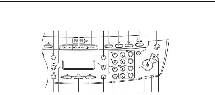
1.1.1.4 Control panel
i-SENSYS MF4690PL / i-SENSYS MF4660
- MF4690PL
[1] [2] |
[3] |
[4] |
[5] [6] [7] [8] |
[9] |
[10] |
[11] [12] |
[13] |
[25][24] |
[23] |
[22] |
[21] |
[20] |
[19] |
[18] |
[17] [16] |
[15] |
[14] |
|
|
|
|
F-1-5 |
|
|
|
|
|
|
|
|
|
T-1-2 |
|
|
|
|
|
[1] [System Monitor] key |
|
|
[14] [Stop/Reset] key |
|
|
|
|||
[2] [View Settings] key |
|
|
[15] Error indicator |
|
|
|
|||
[3] [COPY] key |
|
|
|
[16] Processing/Data indicator |
|
|
|||
[4] [SEND/FAX] key |
|
|
[17] [Start] key |
|
|
|
|
||
[5] [SCAN] key |
|
|
|
[18] Numeric key |
|
|
|
||
[6] [Additional Functions] key |
|
[19] [Tone] key |
|
|
|
|
|||
[7] [2-Sided] key |
|
|
[20] [Clear] key |
|
|
|
|
||
[8] [Enlarge/Reduce] key |
|
|
[21] [+] key |
|
|
|
|
||
[9] [Density] key |
|
|
[22] [OK] key |
|
|
|
|
||
[10] [Image Quality] key |
|
|
[23] [-] key |
|
|
|
|
||
[11] [Collate/2 on 1] key |
|
|
[24] LCD display |
|
|
|
|||
[12] [Log In/Out] key (ID) key |
|
[25] [Toner Gauge] key |
|
|
|
||||
[13] [Energy Saver] key |
|
|
|
|
|
|
|
|
|
1-4

Chapter 1
- MF4660PL
[1] [2] |
[3] |
[4] |
[5] [6] [7] |
[8] |
[9] |
[10] [11] |
[12] |
[24][23] |
[22] |
[21] |
[20] |
[19] |
[18] |
[17] |
[16] [15] |
[14] |
[13] |
|
|
|
|
F-1-6 |
|
|
|
|
|
|
|
|
|
T-1-3 |
|
|
|
|
|
[1] [System Monitor] key |
|
|
[13] [Stop/Reset] key |
|
|
|
|||
[2] [View Settings] key |
|
|
[14] Error indicator |
|
|
|
|||
[3] [COPY] key |
|
|
|
[15] Processing/Data indicator |
|
|
|||
[4] [SCAN] key |
|
|
|
[16] [Start] key |
|
|
|
|
|
[5] [Additional Functions] key |
|
[17] Numeric key |
|
|
|
||||
[6] [2-Sided] key |
|
|
[18] [Tone] key |
|
|
|
|
||
[7] [Enlarge/Reduce] key |
|
|
[19] [Clear] key |
|
|
|
|
||
[8] [Density] key |
|
|
[20] [+] key |
|
|
|
|
||
[9] [Image Quality] key |
|
|
[21] [OK] key |
|
|
|
|
||
[10] [Collate/2 on 1] key |
|
|
[22] [-] key |
|
|
|
|
||
[11] [Log In/Out] key (ID) key |
|
[23] LCD display |
|
|
|
||||
[12] [Energy Saver] key |
|
|
[24] [Toner Gauge] key |
|
|
|
|||
- MF4690PL only |
|
|
|
|
|
|
|
|
|
|
|
|
|
[1] |
[2] |
[3] |
[4] |
|
|
|
[6] |
[5] |
|
F-1-7 |
|
|
T-1-4 |
|
[1] [Hook] key |
[4] [Address Book] key |
|
[2] [Recall/Pause] key |
[5] R key |
|
[3] [Coded Dial] key |
[6] One-Touch Speed Dial keys |
|
1.1.2 Safety
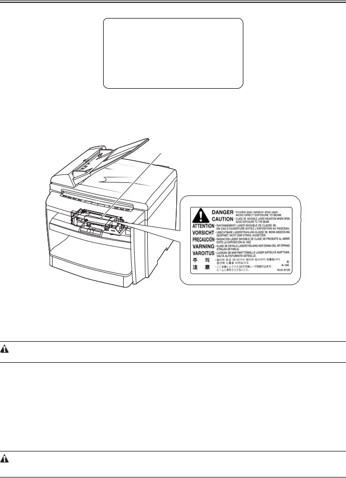
1.1.2.1 Safety of the Host Machine's Laser Mechanism i-SENSYS MF4690PL / / i-SENSYS MF4660
Laser radiation can prove to be harmful to the human body. The host machine's laser scanning system is completely sealed by means of a protective housing and external covers so that its light will not leak outside the host machine as long as the host machine is used normally.
1.1.2.2 CDRH Regulations
i-SENSYS MF4690PL / / i-SENSYS MF4660
The Center for Devices and Radiological Health (CDRH) of the US Food and Drug Administrator put into forth regulations that relate to laser products on August 2nd, 1976.
These regulations apply to laser products produced on and after August 1st, 1976, and prohibit the sale of laser products without certification.
1-5
Chapter 1
The following labels certify compliance with the CDRH regulations, and must be attached to all laser products that are sold in the US.
CANON
30-2, SHIMOMARUKO, 3-CHOME, OHTAKU, TOKYO, 146, JAPAN.
MANUFACTURED:
THIS PRODUCT CONFORMS WITH DHHS RADIATION
PERFORMANCE STANDARD 21CFR CHAPTER 1
SUBCHAPTER J.
F-1-8
1.1.2.3 Handling of the Laser Assembly i-SENSYS MF4690PL / / i-SENSYS MF4660
Invisible laser beam is radiated within the laser scanner unit. Laser beam radiation may pose damage to eyes. Be sure not to disassemble the laser scanner unit. The host machine's laser scanner unit cannot be adjusted in the field. The label [1] shown in the figure below is attached onto the cover of the laser scanner unit.
[1]
F-1-9
1.1.2.4 Safety of the Toner i-SENSYS MF4690PL / / i-SENSYS MF4660
Toner in General
Toner is a non-toxic material made up of plastic, iron, and small amounts of dye.
Do not throw toner into fire. Doing so can lead to explosion.
Contact with Toner
1.Toner on the skin or clothes must be removed by washing with water immediately.
2.The use of warm water must be avoided, doing so will cause the toner to turn gel-like and to permanently fuse with the fibers of the clothes.
3.Contact with vinyl must also be avoided, as toner can readily react.
1.1.2.5 Fire Attention
i-SENSYS MF4690PL / / i-SENSYS MF4660
It is dangerous to throw the parts that include combustible materials such as lithium battery and toner cartridge etc., into fire. Any used battery must always be disposed according to the appropriate local regulations.
1.1.2.6 Points no Note when Replacing / Disposing the Lithium Battery i-SENSYS MF4690PL / / i-SENSYS MF4660
Replacing to wrong type of battery may cause explosion.
Dispose used battery according to the instruction manual.
1-6

Chapter 1
1.1.3 Product Specifications
1.1.3.1 Host Machine Specifications i-SENSYS MF4690PL / i-SENSYS MF4660
Copyboard |
Fixed |
|
|
Body |
Desktop (ADF standard type) |
|
|
Light source type |
LED |
|
|
Image reading method |
Contact Sensor Reading Method |
|
|
Photosensitive medium |
OPC drum |
|
|
Reproduction method |
Indirect electrostatic copying method |
|
|
Exposure method |
Semiconductor laser |
|
|
Charging method |
Roller contact charging method |
|
|
Development method |
Dry system - element jumping development method |
|
|
Transfer method |
Roller transfer method |
|
|
Separation method |
Electrostatic separation (neutralizing needle) and curvature separation |
|
|
Pickup method |
Cassette pick-up: 1 cassette |
|
Multi manual feeding pick-up |
|
|
Cassette pickup method |
Pad separation method |
|
|
Multifeeder pickup method |
Pad separation method |
|
|
Drum cleaning method |
Rubber blade |
|
|
Fixing method |
On-demand fixing |
|
|
Toner supply type |
By drum style toner cartridge |
|
|
Toner type |
Magnetic negative toner |
|
|
Toner save mode |
Yes |
|
|
Original type |
Sheets, books, solids (up to 2 kg) |
|
|
Maximum original size |
Fixed: 216mm x 297mm |
|
ADF: 216mm x 356mm |
|
|
Reproduction ratio |
1 to 1 + / - 1.0 %, 1 to 2.00, 1 to 1.29, 1 to 0.78, 1 to 0.64, 1 to 0.50 |
|
Zoom: 0.50 to 2.00 (specified by the percent) |
|
|
Reading resolution |
<TEXT/PHOTO>: 300 dpi x 300 dpi |
|
<TEXT>, <PHOTO>, <TEXT/PHOTO+>: 600 dpi x 600 dpi |
|
|
Printing resolution |
600 x 600 dpi |
|
|
Warm-up time |
9.0 seconds or less* |
|
(temperature: 20 deg C, humidity: 65%. From when turning on the main |
|
power of this product until the standby screen is displayed) |
|
*Warm-up time may vary according to use condition of this product and |
|
environment) |
|
|
First print time |
8.5 seconds or less (A4/LTR) |
|
|
Print speed |
Approximately 20 sheets / minute (A4) |
|
Approximately 21 sheets / minute (LTR) |
|
Double-sided: |
|
Approximately 5 sheets / minutes |
|
|
Cassette paper size |
LTR, LGL, A4, B5, A5, Executive, Envelope (COM10, Monarch, |
|
DL,ISO-C5), Oficio, Brazil-Oficio, Mexico-Oficio, Folio, Government- |
|
LTR, Government-LGL, Foolscap (76 x 127 to 216 x 356 mm) |
|
|
Multifeeder paper size |
LTR, LGL, A4, B5, A5, Executive, Envelope (COM10, Monarch, |
|
DL,ISO-C5), Oficio, Brazil-Oficio, Mexico-Oficio, Folio, Government- |
|
LTR, Government-LGL, Foolscap (76 x 127 to 216 x 356 mm) |
|
*For 2-sided prints, only for 64 to 80g/m2-A4/LTR |
|
|
Cassette paper type |
Plain paper (64 to 90g / m2), thick paper (105 to 128g / m2), recycled |
|
paper (64 to 80g / m2), transparency, label, envelop, and postcard |
|
|
Multifeeder tray paper type |
Plain paper (64 to 90g / m2), thick paper (105 to 128g / m2), recycled |
|
paper (64 to 80g / m2), transparency, label, envelop, and postcard |
|
|
Cassette capacity |
250 sheets (80g / m2 paper) |
Multifeeder tray capacity |
10 sheets (plain paper: 80g / m2 paper) |
|
1 sheet (transparency, envelop) |
|
|
Delivery tray stack |
100 sheets (plain paper: 80g / m2 paper) |
|
50 sheets (thick paper: 91 to 105g / m2 paper) |
|
30 sheets (thick paper: 106 to 128g / m2 paper) |
|
10 sheets (label, transparency, envelop, postcard) |
|
|
Continuous reproduction |
1 to 99 sheets |
|
|
Energy save mode |
Yes. (Manual ON / OFF, automatically OFF after a set period of time, |
|
automatically ON when receiving facsimile / print data) |
|
|
Network |
Yes |
|
|
PDL |
UFRII LT, PCL5 / PCLXL |
|
|
1-7
Chapter 1
SEND |
MF4660: No |
|
MF4690: Yes |
|
|
Operating environment |
15 to 30 degrees C |
(temperature range) |
|
|
|
Operating environment |
10 to 80 % |
(humidity range) |
|
|
|
Operating environment |
0.16 to 1.01 hPa (0. 6 to 1 bar) |
(atmospheric pressure) |
|
|
|
Power supply rating |
220V-240V (50/60Hz) |
|
|
Power consumption (maximum) |
Maximum consumption: less than 730W |
|
|
Power consumption |
During operation: approximately 340W or less (reference value) |
|
At standby: approximately 12W (referenve velue)In sleep mode: |
|
approximately 3W (reference value) |
|
|
Ozone |
Maximum: less than 0.05 ppm, average: less than 0.02 ppm |
|
|
Dimensions |
390mm (W) x 442mm (D) x 470mm (H) (with original pick-up tray) |
|
|
Weight |
Approximately 13.4kg (including toner cartridges) |
|
|
1.1.3.2 ADF Specifications i-SENSYS MF4690PL / / i-SENSYS MF4660
Original orientation |
Face-up method |
Original position |
center reference |
|
|
Original processing mode |
1-sided to 1-sided copy, 1-sided to 2-sided copy |
|
|
Original reading |
stream reading method |
|
|
Stack |
35 sheets (80 g/m2 or less) |
|
15 sheets (LGL size) |
|
|
Mixed original sizes |
No |
|
|
Original AE detection |
No |
|
|
Original size recognition |
No |
|
|
Stamp |
No |
|
|
Operating environment |
pursuant to the host machine |
|
|
1.1.3.3 FAX Specifications i-SENSYS MF4690PL /
Applicable lines |
Analog line (single line) |
|
- Telephone subscriber line (PSTN) |
|
|
Transmission method |
Half-duplex communication |
|
|
Modulation method |
<G3 image signal> |
|
ITU-T V.27 ter (2.4Kbps, 4.8Kbps) |
|
ITU-T V.29 (7.2Kbps, 9.6Kbps) |
|
ITU-T V.17 (TC7.2Kbps, TC9.6Kbps, 12Kbps, 14.4Kbps) |
|
ITU-T V.34 (2.4Kbps, 4.8Kbps, 7.2Kbps, 9.6Kbps, 12Kbps, 14.4Kbps, |
|
16.8Kbps, 19.2Kbps, 21.6Kbps, 24Kbps, 26.4Kbps, 28.8Kbps, |
|
31.2Kbps, 33.6Kbps) |
|
<G3 procedure signal> |
|
ITU-T V.21 No.2 (300bps) |
|
ITU-T V.8, V.34 (1200bps) |
|
|
Transmission speed |
33.6Kbps, 31.2Kbps, 28.8Kbps, 26.4Kbps, 24Kbps, 21.6Kbps, |
|
19.2Kbps, 16.8Kbps, 14.4Kbps, 12Kbps, TC9.6Kbps, TC7.2Kbps, |
|
9.6Kbps, 7.2Kbps, 4.8Kbps, 2.4Kbps |
|
With automatic fallback function |
|
|
Coding |
MMR, MR, MH, JBIG |
|
|
Error correction |
ITU-T ECM |
|
|
Minimum receive input level |
V.17, V.27ter, V.29: -6 to -43 dBm |
|
V.34: -10 to -43 dBm |
|
|
Modem IC |
CONEXANT DFX336 |
|
|
Scanning line density |
Standard: 8 dots / mm x 3.85 lines / mm |
|
Fine: 8 dots / mm x 7.7 lines / mm |
|
Super fine: 8 dots / mm X 15.4 lines / mm |
|
Ultra fine: 16 dots / mm X 15.4 lines / mm |
|
|
Half tone |
256 gradation sequence |
|
|
Printing resolution |
600 dpi x 600 dpi |
|
|
Reduction for reception |
Fixed reduction: 90%, 95%, 97%, 75% |
|
Automatic reduction: 75 to 100% |
|
|
FAX/TEL switching |
Yes |
|
|
Answering machine connection |
Yes |
Remote reception |
ID entry method |
|
ID: 2 digits (default is 25) |
|
|
Auto dialing |
One-touch dial: 8 |
|
Speed dial: 192 |
|
Group dial: Maximum 199 |
|
|
1-8

Chapter 1
Delayed transmission |
No |
Broadcast transmission |
Number of Destination: Maximum 201 |
|
|
Dual access |
Number of reservations: 70 max. |
|
|
Image data backup |
backup particulars: memory reception, memory transmission, broadcast |
|
image data |
|
backup IC: 128 MB (SDARAM) |
|
Backup battery: rechargeable capacity |
|
backup length: about 1 hour |
|
|
1-9

Chapter 2 Basic Operation

Contents
Contents
2.1 |
Construction ................................................................................................................................................................... |
2-1 |
2.1.1 Function Configuration................................................................................................................................................................ |
2-1 |
|
2.2 |
Basic Sequence .............................................................................................................................................................. |
2-1 |
2.2.1 Basic Operation Sequence ........................................................................................................................................................... |
2-1 |
|
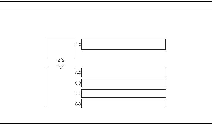
Chapter 2
2.1 Construction
2.1.1 Function Configuration i-SENSYS MF4690PL / / i-SENSYS MF4660
The functions of this host machine are mainly composed of the 7 blocks: System
Control System, Scanning Control System, Printer Control System, Laser Scanner System, Image Formation System, Fixing System, Pickup/Feeding System. Below is the block diagram.
System Control
System
Printer Control
System
Scanning Control System
Laser / Scanner System
Image Formation System
Fixing System
Pickup / Feeding System
F-2-1
2.2 Basic Sequence
2.2.1 Basic Operation Sequence i-SENSYS MF4690PL / / i-SENSYS MF4660
The operations of this host machine are controlled by CPUs of the SCNT board within the Reader Controller System and the DCNT board within the Engine Control System. The table below shows the purpose of each interval and the outline of the operations of reader unit and the engine from turnon of the power supply to stop of each motor after printing.
T-2-1
interval name |
definition of interval |
purpose |
remarks |
WAIT (wait) |
Interval between turnon of the |
To clear the drum surface potential |
Presence/absence of cartridge is detected during this interval. |
|
power supply and the end of the |
and to execute the cleaning of |
|
|
initial drive |
transfer charging roller |
|
|
|
|
|
STBY (standby) |
Interval between the end of WAIT |
To make the host machine ready for |
|
|
or LSTR and input of print |
printing |
|
|
command from SCNT board, or |
|
|
|
interval between the end of LSTR |
|
|
|
and turnoff of power supply |
|
|
|
|
|
|
INTR (initial rotation) |
Interval between the input of print |
To stabilize the photosensitive drum |
|
|
command from SCNT and turnon |
as a preparation for printing |
|
|
of the pickup solenoid |
Also to clean the transfer charging |
|
|
|
roller |
|
|
|
|
|
PRINT (print) |
Interval between the end of initial |
To form an image onto the |
|
|
rotation and turnoff of the primary |
photosensitive drum based on the |
|
|
high-voltage output |
video signal input from the SCNT |
|
|
|
board and to transfer the toner image |
|
|
|
onto media |
|
|
|
|
|
LSTR (last rotation) |
Interval between turnoff of the |
To fully deliver the final sheet |
On input of print command from the SCNT board, host machine |
|
primary high-voltage output and |
printed |
enters INTR immediately after LSTR. However, depending on the |
|
stop of the main motor |
Also to clean the transfer charging |
conditions shown below, the host machine may not start INTR |
|
|
roller |
immediately. |
|
|
|
-media size |
|
|
|
-temperature of the fixing assembly |
|
|
|
|
2-1

Chapter 3 Original Exposure System

Contents
Contents
3.1 Basic Constraction ......................................................................................................................................................... |
3-1 |
3.1.1 Specifications / Control / Function List ....................................................................................................................................... |
3-1 |
3.1.2 Major Components....................................................................................................................................................................... |
3-1 |
3.2 Various Control.............................................................................................................................................................. |
3-2 |
3.2.1 Dirt Sensor Control ...................................................................................................................................................................... |
3-2 |
3.2.1.1 Outline............................................................................................................................................................................................................. |
3-2 |
3.3 Parts Replacement Procedure......................................................................................................................................... |
3-4 |
3.3.1 Scanner Unit................................................................................................................................................................................. |
3-4 |
3.3.1.1 Preparation for Removing the Control Panel Assembly ................................................................................................................................. |
3-4 |
3.3.1.2 Removing the Control Panel Assembly .......................................................................................................................................................... |
3-4 |
3.3.2 Book Motor.................................................................................................................................................................................. |
3-4 |
3.3.2.1 Preparation for Removing the Flat Bed Motor ............................................................................................................................................... |
3-4 |
3.3.2.2 Removing the Flat Bed Motor......................................................................................................................................................................... |
3-4 |
3.3.3 Contact Sensor ............................................................................................................................................................................. |
3-5 |
3.3.3.1 Removing the Contact Sensor......................................................................................................................................................................... |
3-5 |

Chapter 3
3.1 Basic Constraction
3.1.1 Specifications / Control / Function List i-SENSYS MF4690PL / / i-SENSYS MF4660
|
T-3-1 |
item |
function / method |
|
|
document exposure |
LED |
document scan |
Book mode: scan by the shift of the contact Book mode: scan by the shift of the contact sensor (CS) |
|
ADF: document stream reading by fixed contact sensor (CS) |
scanning resolution |
600 dpi (horizontal scanner) X 600 dpi (vertical scanner) |
number of gradations |
256 gradations |
magnification |
50% to 200% |
|
horizontal: image processing by SCNT board |
|
vertical: change of carriage shift speed, image processing by SCNT board |
lens |
rod lens array |
CMOS sensor |
number of lines: 1 line |
|
number of pixels: 5184 pixels as total pixels (5107 pixels as effective pixels) |
|
maximum document scanning width: 216 mm |
CS drive control |
drive control by Book motor (M2) |
CS HP detection |
Yes |
document size detection |
none |
Dirt sensor detection |
Yes |
3.1.2 Major Components
i-SENSYS MF4690PL / / i-SENSYS MF4660
Followings are the major components for Document Exposure System.
-The contact sensor to scan document
-The Book motor (M2), the drive pulley, the drive belt, to shift the contact sensor
In image scanning control, the contact sensor is shifted by rotating the Book motor based on the drive signal from the DCNT board and scan the original on the copyboard glass. When ADF is in use, image is scanned by feeding the originals by ADF instead of shifting the contact sensor.
drive belt
drive pulley
Book motor (M2)
drive pulley |
contact sensor |
|
F-3-1 |
3-1

Chapter 3
3.2 Various Control
3.2.1 Dirt Sensor Control
3.2.1.1 Outline
i-SENSYS MF4690PL / / i-SENSYS MF4660
The machine changes the original read position or corrects the read image depending on the presence/absence of dust on the stream reading glass or ADF platen roller, thus preventing dust from showing up in the image. This control is performed only when the ADF is used and it is closed.
[Control Timing]
- At job end
Main power |
Start key |
|
|
switch |
|
|
ON |
ON |
|
|
|
|
WMUPR |
STBY |
1st |
|
2nd |
|
||
SCAN |
|
SCAN |
Dust detection control
Dust detection control
Dust detection control
F-3-2
[Description of Control] - At job completion:
The contact sensor (CS) detects the reflecting light from the surface of the ADF platen guide at scanning position to judge if there is dust at the point.
After the job is complete, dust detection is performed three times. First the detection is performed at "A" position and if there is no dust, then it is performed twice more. If no duct is detected for three times, the document is scanned at "A" position. In case the dust is detected at "A" position, it moves to "B" position to perform dust detection twice. If no dust is detected at "B" position, the document is scanned at "B" position. In case the dust is also detected at "B" position, it moves to "C" position to perform dust detection once. In case the dust is also detected at "C" position, it returns to "A" position to scan the document.
- In the control at job completion, if dust is detected at all three positions (A/B/C), a message is displayed on the control panel to encourage cleaning of glass surface.
0.5mm 0.5mm
A B C
Stream |
|
reading glass |
Platen guide |
|
Lens
LED
Contact sensor
F-3-3
The original is read at the position determined at job end or start. If presence of dust is detected there, the read image is corrected.
3-2

Chapter 3
T-3-2
Position Description
AReference position for scanning
BApprox. 0.5mm from the reference point
CApprox. 1.0mm from the reference point
3-3
Loading...