


 Loading...
SERVICE HANDBOOK
REVISION 0
JAN.1998 FY8-23AV-000
COPYRIGHT © 1998 CANON INC. CANON PC400/420/430,FC200/220 REV.0 JAN.1998 PRINTED IN JAPAN (IMPRIME AU JAPON)

IMPORTANT
THIS DOCUMENTATION IS PUBLISHED BY CANON INC., JAPAN, TO SERVE AS A SOURCE OF REFERENCE FOR WORK IN THE FIELD.
SPECIFICATIONS AND OTHER INFORMATION CONTAINED HEREIN MAY VARY SLIGHTLY FROM ACTUAL MACHINE VALUES OR THOSE FOUND IN ADVERTISING AND OTHER PRINTED MATTER.
ANY QUESTIONS REGARDING INFORMATION CONTAINED HEREIN SHOULD BE DIRECTED TO THE COPIER SERVICE DEPARTMENT OF THE SALES COMPANY.
THIS DOCUMENTATION IS INTENDED FOR ALL SALES AREAS, AND MAY CONTAIN INFORMATION NOT APPLICABLE TO CERTAIN AREAS.
COPYRIGHT © 1998 CANON INC.
Printed in Japan
Imprimé au Japon
Use of this manual should be strictly
supervised to avoid disclosure of
confidential information.
Prepared by
OFFICE IMAGING PRODUCTS TECHNICAL SUPPORT DEPARTMENT 1 OFFICE IMAGING PRODUCTS TECHNICAL SUPPORT DIVISION
CANON INC.
5-1, Hakusan 7-chome, Toride-shi, Ibaraki 302 Japan
COPYRIGHT © 1998 CANON INC. CANON PC400/420/430,FC200/220 REV.0 JAN.1998 PRINTED IN JAPAN (IMPRIME AU JAPON)

CONTENTS
CHAPTER 1 MAINTENANCE AND INSPECTION
|
|
|
|
|
A. |
.........Periodically Replaced Parts |
1-1 |
2. Storing and Handling Unsealed |
|
B. |
Durables....................................... |
1-1 |
Cartridges ............................... |
1-3 |
C. |
Periodical Servicing ..................... |
1-1 |
E. Image Adjustment Basic Procedure |
|
D. |
Notes on Cartridge....................... |
1-2 |
..................................................... |
1-5 |
|
1. Storing Sealed Cartridges....... |
1-2 |
F. Points to Note .............................. |
1-6 |
|
|
|
|
|
|
|
|
|
|
CHAPTER 2 STANDARDS AND ADJUSTMENTS
A. Mechanical................................... |
2-1 |
1.Image Leading Edge Non-Image Width (position of white paint on
back of glass).......................... |
2-1 |
2.Image Leading Edge Margin (point of detection for registration)
................................................2-1
B. Electrical ...................................... |
2-2 |
1.Adjusting the Intensity (VR604)
................................................2-2
2.Adjusting the AE Mechanism
(VR602, VR603) ..................... |
2-4 |
CHAPTER 3 IMAGE TROUBLESHOOTING
A. Making Initial Checks ................... |
3-1 |
|
1. |
Site Environment .................... |
3-1 |
2. |
Checking the Documents........ |
3-1 |
3.Checking the Copyboard Cover and Copyboard Glass for Dirt
and Scratches......................... |
3-2 |
4.Checking the Lens Array for Dirt
................................................3-2
5.Checking the Transfer Charging
Roller ...................................... |
3-2 |
6.Checking the Feeding Assembly
|
................................................ |
3-2 |
7. |
Checking the Copy Paper....... |
3-2 |
8. |
Checking the Durables ........... |
3-2 |
9. |
Others ..................................... |
3-4 |
B. Samples of Image Faults ............. |
3-6 |
|
C. Troubleshooting by Image Fault |
3-7 |
|
..................................................... |
|
|
1.The copy is too light (halftone
areas only). ............................. |
3-7 |
2.The copy is too light (dark areas
as well).................................... |
3-7 |
3.The copy is too light (extremely
light overall). ........................... |
3-7 |
4.The copy has uneven density
(darker at front). ...................... |
3-8 |
5.The copy has uneven density
(lighter at front). ...................... |
3-8 |
6. The copy is foggy (overall)...... |
3-8 |
7.The copy is foggy (paper feed
direction). ................................ |
3-9 |
8.The copy has dark lines (paper feed direction, relatively narrow).
................................................3-9
9.The copy has dark lines (paper
|
feed direction, thin). |
................3-9 |
10. |
The copy has white spots (paper |
|
|
feed direction). ........................ |
3-9 |
11. |
The copy has white lines (paper |
|
|
feed direction). ........................ |
3-9 |
12. |
The copy has white spots (cross |
|
|
feed direction). ...................... |
3-10 |
13. |
The back of the copy is soiled. |
|
|
.............................................. |
3-10 |
1
2
3
4
5
6
7
i
14. |
The copy has faulty fixing...... |
3-11 |
15. |
The copy has faulty leading |
|
|
edge registration (blank area |
|
|
much too wide)...................... |
3-11 |
16.The copy has faulty leading edge registration (blank area too
wide)...................................... |
3-11 |
17.The copy has faulty leading edge registration (no blank area)
..............................................3-11
18. |
The copy has a blurred image. |
|
|
.............................................. |
3-12 |
19. |
The copy is foggy (cross feed |
|
|
direction). .............................. |
3-12 |
20. |
The copy has poor sharpness |
|
|
(focus)................................... |
3-12 |
21. |
The copy is blank.................. |
3-13 |
22. |
The copy is solid black.......... |
3-13 |
CHAPTER 4 TROUBLESHOOTING MALFUNCTIONS
A. Troubleshooting Malfunctions ...... |
4-1 |
1. (self diagnosis;PC400/FC200)
|
...................................... |
4-1 |
2. |
E0 ........................................... |
4-1 |
3. |
E2 ........................................... |
4-2 |
4. |
E6 ........................................... |
4-2 |
5. |
E9 ........................................... |
4-3 |
6. |
AC power is absent................. |
4-3 |
7. |
Pick-up fails. ........................... |
4-4 |
8.The scanning lamp fails to go
ON. ......................................... |
4-4 |
9.The main motor fails to rotate.
10. |
The................................................copyboard fails to move. |
4-5 |
|
4-5 |
|||
|
................................................ |
||
11. |
(paper feeding normally) .... |
4-6 |
|
12. |
(at time of jam) ................... |
4-6 |
|
13. |
The fixing heater fails to operate |
||
|
................................................ |
4-6 |
|
CHAPTER 5 TROUBLESHOOTING PAPER FEED PROBLEMS
|
|
|
|
|
|
........................A. Copy Paper Jams |
5-1 |
.............................B. Feeding Faults |
5-4 |
||
1. |
Pick-Up Assembly................... |
5-2 |
1. |
Double Feeding ...................... |
5-4 |
2. |
Separation/Feeding Assembly |
5-2 |
2. |
Wrinkles .................................. |
5-4 |
|
................................................ |
|
|
|
|
3.Fixing/Delivery Assembly
................................................5-3
CHAPTER 6 ARRANGEMENT AND FUNCTIONS OF ELECTRICAL PARTS
|
|
|
|
|
|
A. |
................Sensors and Solenoids |
6-1 |
E. Variable Resistors (VR) and Check |
||
B. |
Switches....................................... |
6-2 |
Pins by PCB................................. |
6-5 |
|
C. |
Lamp, Heater, Motor, and Others |
|
1. |
DC Controller/DC Power Supply |
|
|
..................................................... |
6-3 |
|
PCB ........................................ |
6-5 |
D. |
Printed Circuit Board (PCB) ......... |
6-4 |
2. |
Control Panel PCB.................. |
6-6 |
ii
COPYRIGHT © 1998 CANON INC. CANON PC400/420/430,FC200/220 REV.0 JAN.1998 PRINTED IN JAPAN (IMPRIME AU JAPON)

CHAPTER 7 SELF DIAGNOSIS
|
|
.....................................Self Diagnosis |
7-1 |
|
|
|
|
APPENDIX
|
|
|
|
|
|
|
A. |
...................General Timing Chart |
A-1 |
C. |
...............General Circuit Diagram |
A-5 |
|
B. |
Signals/Abbreviations List ............ |
A-3 |
D. |
Special Tools Table....................... |
A-7 |
|
|
1. |
Signals.................................... |
A-3 |
E. |
Solvents/Oils Table....................... |
A-8 |
|
2. |
Abbreviations.......................... |
A-4 |
F. |
Specifications ............................... |
A-9 |
COPYRIGHT © 1998 CANON INC. CANON PC400/420/430,FC200/220 REV.0 JAN.1998 PRINTED IN JAPAN (IMPRIME AU JAPON)
iii
iv
COPYRIGHT © 1998 CANON INC. CANON PC400/420/430,FC200/220 REV.0 JAN.1998 PRINTED IN JAPAN (IMPRIME AU JAPON)
|
|
|
|
1 |
|
CHAPTER 1 MAINTENANCE AND INSPECTION |
|
||
|
|
|||
|
|
|
|
|
|
|
|
|
|
CHAPTER 1 MAINTENANCE AND INSPECTION
A. Periodically Replaced Parts
The machine does not have parts which must be replaced on a periodical basis.
B. Durables
The machine does not have parts which are classified as durables.
C. Periodical Servicing
The machine does not have parts that require periodical servicing.
1-1

CHAPTER 1 MAINTENANCE AND INSPECTION
D. Notes on Cartridge
The cartridge is affected by the environment, regardless of whether it is sealed or unsealed and installed in the machine or otherwise. Although the properties of the cartridge change over time independent of how many copies have been made, the degree of care taken for the cartridge affects how long it may remain stable.
1. Storing Sealed Cartridges
When storing the cartridge in a warehouse or workshop, make sure the place is controlled to the specifications shown in Table 1-1D.
a.Avoid direct rays of the sun.
b.Avoid areas subjected to appreciable vibration.
c.Do not drop or subject it to impact.
|
Normal |
|
0° to 35°C/ |
|
Temperature |
(9/10 of period) |
|
32° to 95°F |
|
|
|
|
|
|
Severe (1/10 |
|
High |
35° to 40°C/ |
|
of period) |
|
|
95° to 104°F |
|
|
|
|
|
|
|
|
Low |
-20° to 0°C/ |
|
|
|
|
-4° to 32°F |
|
|
|
|
|
|
|
|
|
|
|
Temperature fluctuations |
40° 15°C/ |
|||
(within about 3 min) |
|
104° 59°F |
||
|
|
|
|
-20°C 25°C/ |
|
|
|
|
-4°F 77°F |
|
|
|
|
|
Humidity |
Normal |
|
35 to 85%RH |
|
(9/10 of period) |
|
|
||
|
|
|
||
Severe (1/10 |
|
High |
85 to 95%RH |
|
of period) |
|
|
|
|
|
Low |
10 to 35%RH |
||
|
|
|||
|
|
|
||
|
|
|
|
|
Atmospheric pressure |
|
460 to 760 mmHg |
||
|
|
|
|
(0.1 to 1 atm) |
|
|
|
|
|
Table 1-1D Temperature/Humidity Specifications
Temperature |
Humidity |
|
|
-20° to 40°C/-4° to 104°F |
90% or less |
|
|
Table 1-2D Transportation
1-2

CHAPTER 1 MAINTENANCE AND INSPECTION
2. Storing and Handling Unsealed Cartridges
The photosensitive medium is an organic photoconductor (OPC), which is extremely susceptible to light. Since the cartridge also contains toner, you must be extra careful when storing or handling the cartridge. Make sure the user is aware of this fact and will handle the cartridge with care.
a.Storing Unsealed Cartridges
1)Avoid areas subjected to strong rays of the sun. Do not keep it in a car even in a protective box; the inside may become extremely hot.
2)Avoid areas of high or low temperature/ humidity and areas where these elements tend to change rapidly (for example, near air conditioners or heaters).
3)Avoid areas where dust, ammonium gas, or gases from organic solvents tend to accumulate.
4)Keep the cartridge in a place 40°C or less.
b.Handling the Cartridge
1)Before inserting the cartridge in the copier or if the toner starts to run short, hold the cartridge horizontally as shown in Figure 1-1, and rotate it in both directions about 90° to even out the toner inside it. Do not shake the cartridge or hold it in a different way; otherwise, toner may leak out the cartridge.
Figure 1-1D
1-3
CHAPTER 1 MAINTENANCE AND INSPECTION
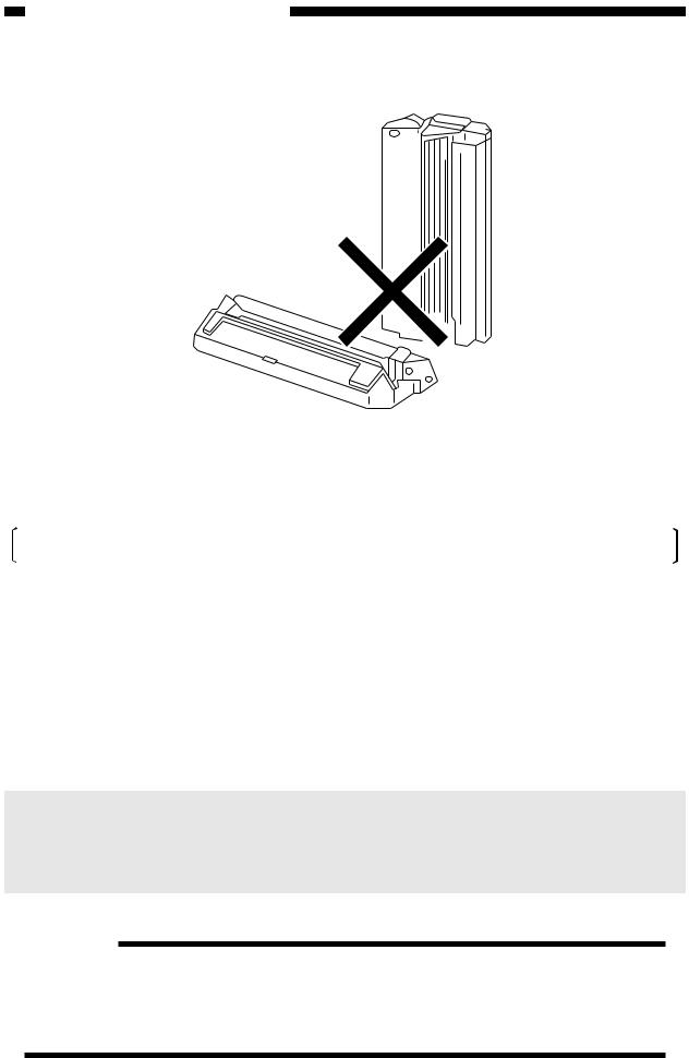
2) Do not place the cartridge upright or upside down; do not shake it.
Figure 1-2D
3)Do not force open the shutter for the photosensitive drum cover found at the bottom of the cartridge; do not touch the surface of the photosensitive drum.
If the surface of the photosensitive drum has become soiled, wipe it using a flannel cloth coated with toner. Do not dry wipe it or use solvent.
4)Do not disassemble the cartridge.
5)Do not subject the cartridge to vibration or impact; in particular, do not force down the photosensitive drum from above the shutter for the drum cover.
6)Keep the cartridge out of reach of children.
7)The photosensitive drum is susceptible to light and, therefore, equipped with a lightblocking shutter; nevertheless, exposure to light for a long time can affect the drum, resulting in copies with white spots or vertical lines. Leave the copier alone for some time for possible recovery; to avoid residual memory, which results in white spots or vertical lines, however, keep the following in mind.
Caution:
Work quickly when removing jams or replacing cartridges.
When the cartridge must be removed for work, be sure to put the cartridge in its storage box or cover it; do not leave it without protective measures once it is outside the copier.
Reference:
The drum would recover to more or less its normal condition if left alone for five minutes in a dark place after exposure to an intensity of 1500 lux (about 5 minutes under general lighting). However, you must try to avoid any exposure. (The rays of the sun have intensities ranging between about 10000 and 30000 lux.)
1-4
<Pre-Checks>
Clean the parts.
Scanning system, pick-up/feeding system, and delivery assembly.
|
Is the |
NO |
setting of the density |
|
correction switch at the |
|
middle? |
|
YES |
Set the switch to the middle.
Select non-AE, and set the density control dial/lever to 5.5; then, make two to three copies of the Test Chart (NB-3, NA-2, NA-3); see Note 1.
Check the following:
1.Density of gray scale No. 9; see Note 2.
2.Difference in density between front and rear; see
Note 3.
3.Density of gray scale No. 1; see Note 3.
4.Fogging in white area; see Note 3.
<Optimum Density Adjustment> |
||
Is gray |
YES |
|
scale No. 9 barely noted? |
||
|
||
(See Note 2.) |
|
|
NO |
|
|
Is the |
|
|
problem corrected by |
YES |
|
the density correction |
|
|
switch? |
|
|
NO |
|
|
Is |
|
|
optimum |
|
|
density obtained by |
YES |
|
adjusting the intensity of |
|
|
light? |
|
|
(See |
|
|
NO |
|
|
Check the following:
1.Cartridge.
2.Scanning lamp unit.
3.DC controller/DC power supply PCB (see “Troubleshooting by Image Fault”).
E. Image Adjustment Basic Procedure
End.
End.
Notes:
1.If a mono color cartridge is used, set the density control dial to 4.5.
2.If NB3 is used, refer to gray scale No. 10.
3.The machine is not equipped with an adjustment function for each type of image fault; see “Troubleshooting by Image Fault.”
4.For instructions on how to adjust the intensity of light, see p. 2-2.
1-5

F. Points to Note
Cartridge, Transfer charging roller
Parts |
Tools/Solve |
Remarks |
|
|
|
Photosensitive |
Toner |
As a rule, do not |
drum |
|
clean. |
|
|
Do not use solvents. |
|
|
Do not touch the |
|
|
drum. Avoid light. |
|
|
|
Drum cover |
Well-wrung |
Be sure to clean the |
shutter |
moist cloth |
shutter; particles of |
|
|
toner can cause |
|
|
soiled copies. |
|
|
|
Transfer |
Lint-free |
Cleaning |
charging roller |
paper |
Do not use water or |
|
|
solvent. Take care |
|
|
not to touch the |
|
|
roller or leave oil. |
|
|
|
Fixing assembly |
|
|
|
|
|
Parts |
Tools/Solve |
Remarks |
|
|
|
Inlet guide |
Solvent |
|
|
|
|
Optical assembly
Parts |
Tools/Solve |
Remarks |
|
|
|
Lens array |
Cotton wad |
Do not use the wire |
|
|
cleaner meant for |
|
|
conventional |
|
|
machines. |
|
|
|
Scanning lamp |
Blower |
|
|
brush |
|
|
|
|
Electrical |
|
|
|
|
|
Parts |
Tools/Solve |
Remarks |
|
|
|
Intensity/AE |
Blower |
Cleaning |
sensor |
brush |
|
|
|
|
Copyboard
Parts |
Tools/Solve |
Remarks |
|
|
|
Copyboard |
alcohol |
|
cover |
|
|
|
|
|
Copyboard |
alcohol |
|
glass |
|
|
|
|
|
White |
alcohol |
Dirt can soil the |
reflecting strip |
|
leading edge |
|
|
margin, causing |
|
|
jams. |
|
|
|
Pick-up roller assembly |
|
|
Parts |
Tools/Solve |
Remarks |
|
|
|
Pick-up roller |
Well-wrung |
Cleaning |
|
moist cloth; |
|
|
or, alcohol |
|
|
|
|
Registration assembly |
|
|
|
|
|
Parts |
Tools/Solve |
Remarks |
|
|
|
Registration |
Well-wrung |
Cleaning |
roller |
moist cloth |
|
|
|
|
1-6
CHAPTER 2 STANDARDS AND ADJUSTMENTS
CHAPTER 2 STANDARDS AND ADJUSTMENTS
A. Mechanical |
2 |
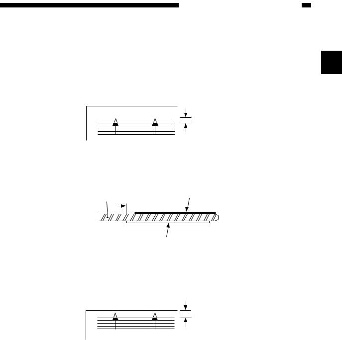
1. Image Leading Edge Non-Image Width (position of white paint on back of |
glass)
The leading edge non-image width must be 2.0 ±1.0 mm when the Test Sheet is copied.
2.0 ± 1.0 [mm]
Figure 2-1A
The leading edge non-image width is determined by the position of the white paint found behind the copyboard glass.
Size index
Copyboard glass
 2mm
2mm
White paint
Figure 2-2A
2.Image Leading Edge Margin (point of detection for registration)
The leading edge margin must be 0.2 to 5.0 mm when the Test Sheet is copied. To adjust, move the position of the registration cam.
0.2 to 5.0 [mm]
Figure 2-3A
2-1
CHAPTER 2 STANDARDS AND ADJUSTMENTS
B. Electrical
Notes:
If you have replaced the scanning lamp unit, intensity sensor, AE sensor, or control panel PCB, you must adjust the three variable resistors on the control panel PCB (one, if PC400/FC200); you must, however, adjust them in the order of VR604, VR602, and VR603 (from intensity to AE).
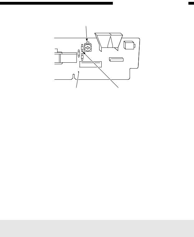
1. Adjusting the Intensity (VR604)
a.After Replacing the Control Panel PCB Only
1)Disconnect the power plug, and detach the faulty control panel PCB.
2)Set the meter to the ‘200 k ’ range, and measure C between the terminal of VR604 and the terminal of R614 on the detached control panel PCB; see Figure 2-1B.
3)Likewise, measure C between the terminal of VR604 and the terminal of R614 on the new control PCB; then, turn VR604 so that the reading is the same as the measurement taken in step 2).
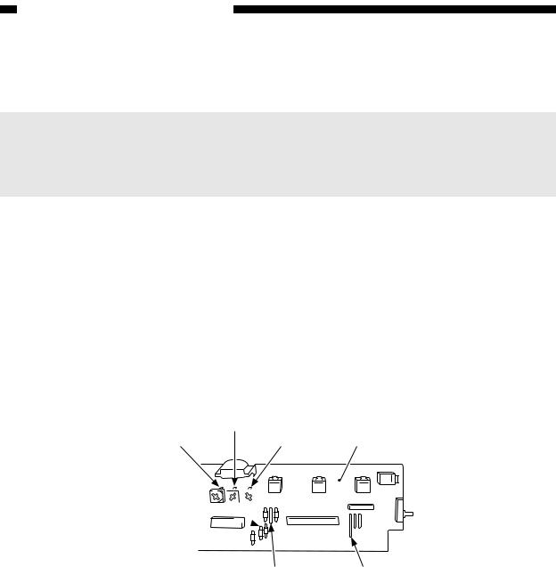
4)In the case of the PC420/430/FC220, adjust VR602 (A between terminals of VR602 and JP607) and VR603 (Between terminals of VR603 and JP621); see Figure 2-1B.
5)Attach the new control panel PCB to the copier.
B (VR603)
A (VR602) C (VR604) Control panel PCB
C (R614) 
|
|
|
|
|
|
|
|
|
|
|
|
|
|
|
|
|
|
|
|
|
|
|
|
|
|
|
|
|
|
|
|
B (JP621) |
A (JP607) |
||||||
Figure 2-1B (PC420/430/FC220)
2-2
CHAPTER 2 STANDARDS AND ADJUSTMENTS
C (VR604)
Control panel PCB |
C (R614) |
Figure 2-2B (PC400/FC200)
b.After Replacing the Scanning Lamp Unit, Intensity Sensor, or AE Sensor
(Before Adjustment)
•If the scanning lamp has blackened, replace it.
•Clean the scanning system (lens array, lamp reflector, lamp).
1)Set the cartridge to the copier.
2)De-select AE, and set the copy density control lever/dial to the center.
3)Set the density correction switch (SW606) to the center (PC420/430/FC220).
4)Set the Test Sheet (NA3/NB3/NA2), and make a copy.
5)Check if the copy is free of fogging, and gray scale No. 9 (No. 10, if NB3) is somewhat visible.
•If too dark,
Turn VR604 on the control panel PCB clockwise slightly to increase the intensity.
•If too light,
Turn VR604 counterclockwise slightly to decrease the intensity.
6)Repeat steps 4) and 5) until the density is optimum.
Notes:
After adjusting the intensity, be sure to adjust the AE mechanism (PC420/430/FC220).
2-3
CHAPTER 2 STANDARDS AND ADJUSTMENTS
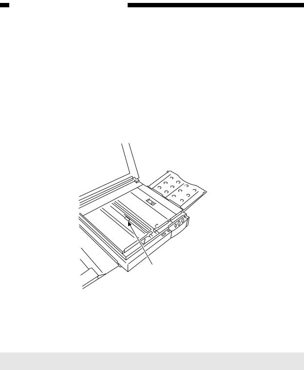
2. Adjusting the AE Mechanism (VR602, VR603)
(Before Adjustment)
•Obtain a newspaper whose text consists of fine print; do not use a section with photos or large characters.
•Make sure you have adjusted light intensity.
1)Switch the copier OFF.
2)Detach the control panel cover.
3)Turn VR602 and VR603 on the control panel PCB fully clockwise.
4)Place a newspaper over the AE light-receiving section of the copyboard, and close the copyboard cover.
AE light-receiving section
Figure 2-3B
5)Short the three jumper wires (JP604, JP605, JP607) on the control panel PCB at the same time using a screwdriver.
Caution:
Take adequate care not to short wires other than those specified.
2-4
CHAPTER 2 STANDARDS AND ADJUSTMENTS
JP607 JP605 JP604
Control panel PCB
Screwdriver
Figure 2-4B
6)While keeping the condition in step 5), switch the copier ON.
• ‘0’ is displayed, the scanning lamp goes ON, and the main motor starts to rotate.
7)Stop shorting the jumper wires.
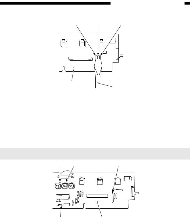
8)Set the digital multimeter to the 20V DC range, and turn VR602 (AE offset adjustment) until the voltage between the anode side of the diode (D606; +) and JP607 (GND) is 4.0 ±0.1 V.
Notes:
You must use a Digital Multimeter when making adjustments in steps 8) and 10).
VR602 |
VR603 |
JP607 |
D606 (anode side) Control panel PCB
Figure 2-5B
2-5

CHAPTER 2 STANDARDS AND ADJUSTMENTS
9)Place about five sheets of blank copy paper.
10)Turn VR603 (AE gain adjustment) until the voltage between the anode side of the diode (D606; it) and JP607 (GND) is 1.8 ±0.1 V; see Figure 2-5B.
11)Switch the copier OFF.
Notes:
Make sure that the jumping wires are no longer shorted.
12)Switch the copier ON once again.
13)Set the density correction switch (SW606) to the center (of the three settings).
14)Make sure that the AE indicator is ON.
15)Set the newspaper used in step 4) on the copyboard once again; this time, move the newspaper to a different area.
16)Make a copy, and make sure that it is not foggy and has adequate text density.
• If foggy,
Turn VR602 clockwise slightly.
• If text density is low,
Turn VR602 counterclockwise slightly.
17) Repeat steps 15) and 16) until the density is optimum.
2-6

CHAPTER 3 IMAGE TROUBLESHOOTING
CHAPTER 3 IMAGE TROUBLESHOOTING
A. Making Initial Checks
1. |
Site Environment |
|
|
|
a. |
The voltage of the power source must be within the specifications. |
|
|
b. |
Avoid areas subjected to dust or high temperature/humidity (near water faucets, |
|
|
|
water boilers, humidifiers) and areas near open fires. |
|
|
c. |
Avoid areas subjected to ammonium gas. |
|
|
3 |
||
|
d. |
Avoid direct rays of the sun; otherwise, provide curtains. |
|
|
e. |
Make sure the site is well ventilated. |
|
|
f. |
Make sure the floor is level. |
|
|
Check the site to see if it meets the above requirements. |
|
|
2. |
Checking the Documents |
|
|
|
You must first check to see if a particular problem may not be due to the document |
|
|
used.
a.The copy density reading should be 5.5 ±1.5 (black)/4.5 ±1.5 (color).
b.Some backgrounds, i.e., yellow shades, tend to produce copies with poor contrast.
c.Diazo copies or translucent documents tend to produce copies that may be mistaken for foggy copies.
d.Documents prepared in light pencil tend to produce copies that may be mistaken for light copies.
3-1
Loading...