


Canon NEW F-1 Service manual
CANON NEW F-1
SERVICE MANUAL
EXPLODED VIEWS
AND
PARTS LIST
CANON INC. JAPAN
Page 1
Canon NEW F-1 Service manual
Contents
1. |
SWITCH POSITION AND NOMENCLATURE ............................................................................................... |
4 |
|
2. |
|
COVERS ................................................................................................................................................................ |
6 |
3. |
FRONT PANEL UNIT ATTACHMENT AND REMOVAL .......................................................................... |
10 |
|
4. |
|
FRONT BODY .................................................................................................................................................... |
12 |
5. |
UPPER BODY (WINDING SIDE)..................................................................................................................... |
16 |
|
6. |
|
TUNGSTEN CABLE ADJUSTMENT .............................................................................................................. |
19 |
7. |
|
SPOOL ................................................................................................................................................................. |
20 |
8. |
|
SPROCKET ......................................................................................................................................................... |
22 |
9. |
|
CHECKS AND ADJUSTMENTS ...................................................................................................................... |
23 |
10. |
UPPER BODY (REWIND SIDE)................................................................................................................... |
31 |
|
11. |
LOWER BODY (I) .......................................................................................................................................... |
34 |
|
12. |
LOWER BODY LUBRICATION.................................................................................................................. |
38 |
|
13. |
LOWER BODY (II) ........................................................................................................................................ |
39 |
|
14. |
ELECTRICAL ADJUSTMENTS .................................................................................................................. |
42 |
|
15. |
FRONT PANEL UNIT ASSEMBLY AND DISASSEMBLY...................................................................... |
50 |
|
16. |
EYE LEVEL FINDER .................................................................................................................................... |
61 |
|
17. |
MOISTURE RESISTANT TREATMENT ................................................................................................... |
66 |
|
18. |
WATER RESISTANT TREATMENT .......................................................................................................... |
68 |
|
19. |
SHUTTER SPEED VARIATIONS ................................................................................................................ |
70 |
|
20. |
SERVICE TOOLS LIST................................................................................................................................. |
71 |
|
21. |
TROUBLESHOOTING CHARTS ................................................................................................................ |
74 |
|
22. |
PARTS LISTS.................................................................................................................................................. |
89 |
|
Page 2
Canon NEW F-1 Service manual
Introduction
The NEW F-1 is the base of a completely new Integrated Functional System. It is based on the original F-1 but utilizing many advances in electronics, precision machining and precision optics made since the original F-1 was developed ten years ago.
The following considerations should be kept in mind when repairing the New F-1:
1.To maintain complete interchangeability between the camera body and the system accessories, repair personnel must understand the interfaces (mechanical
and electronic) between the body and accessories. They must also be familiar with repair standards, checking, adjustment and tools maintenance procedures.
2.Preventive maintenance (lubrication, adjustment and parts replacement) are necessary to insure the reliability of the NEW F-1.
Special Repair Instructions
1.Many of the electrical contacts in the camera are molded into plastic insulators. When making solder connections, the soldering time should be kept as short as possible.
2.3% silver solder should be used to solder the IC's.
3.Many bearing balls are used in the winding mechanism. Be careful during assembly and disassembly to insure that no balls get lost in surrounding mechanisms.
4.When the rewind crank is not installed, if the rewind shaft is pushed down past a certain point it becomes impossible to open the back cover without removing certain parts that normally need not be removed. This results in lost time.
5.Be sure that the elastic connectors used to connect the flexible and rigid circuit boards are kept clean and free of contamination.
6.The water and moisture proofing complicates many repair procedures. Take care that they are correctly performed
7.If the tungsten cable is kinked or frayed, repair is difficult and time-consuming. It is much more cost efficient to be careful to not damage the cable than to repair or replace it.
8.The correct adjustment of the AV AE shutter speed indicator output resistor (RM TV2) and the TV AE aperture determination resistor (RAE) are basic to maintaining system interchangeability.
Page 3
Canon NEW F-1 Service manual
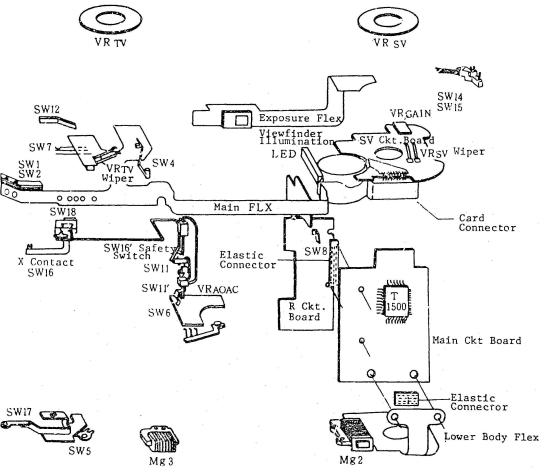
1. Switch position and nomenclature
Name |
Operation |
||
SW1 |
Metering Switch |
ON: |
Metering activated |
SW2 |
Release Switch |
ON: |
Starts Release sequence |
SW4 |
Count Switch |
OFF: Shutter exposure timing starts |
|
SW5 |
Winding Complete Switch |
OFF: Winding complete |
|
SW6 |
Stop-down (S.D.) Switch |
ON: Stopped-down (ganged with SWll1) |
|
SW7 |
Self Timer Switch |
ON: |
Self timer activated |
SW8 |
Battery Check Switch |
ON: |
Battery Check |
SWll |
Lens A-M Switch. |
ON: |
Lens set to "a" mark |
SW1l' Stop-down switch |
OFF: Lens stopped down |
||
SW12 |
Bulb switch |
OFF: "Bulb" shutter speed |
|
SW14 |
Timer Switch |
ON: |
Timer Activated |
SW15 |
Lamp Switch |
ON: |
Viewfinder illumination on |
SW16 |
X Sync Switch |
ON: |
1st curtain open; OFF: Winding complete |
SW16' Safety Switch |
ON: |
Mirror up; OFF: Mirror down |
|
SW17 |
Film End Switch |
ON: |
No film on take-up spool |
SW18 |
2nd Curtain Switch |
OFF: When 2nd curtain starts |
|
Page 4
Canon NEW F-1 Service manual
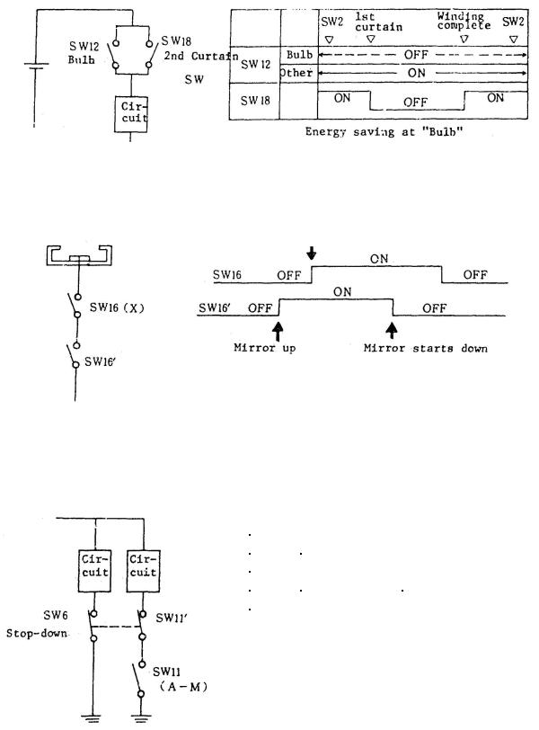
1) SW12 and SW18 Relationship
2) SW16 and SW16' Relationship
1st curtain
X contact must turn off after the 2nd curtain closes and before winding is complete.
3) SW11, SW6 and SW11’ Relationship
|
Lens "A" |
Lens "M" |
||||
|
|
|
|
|
|
|
|
Max. |
|
S.D. |
Max. |
|
S.D. |
SW11 |
|
ON |
|
OFF |
||
SW6,1 |
ON |
|
OFF |
ON |
|
OFF |
Max: Open aperture S.D.:
Stopped down
Page 5

Canon NEW F-1 Service manual
2. Covers
Numbers 1-37
Page 6
Canon NEW F-1 Service manual
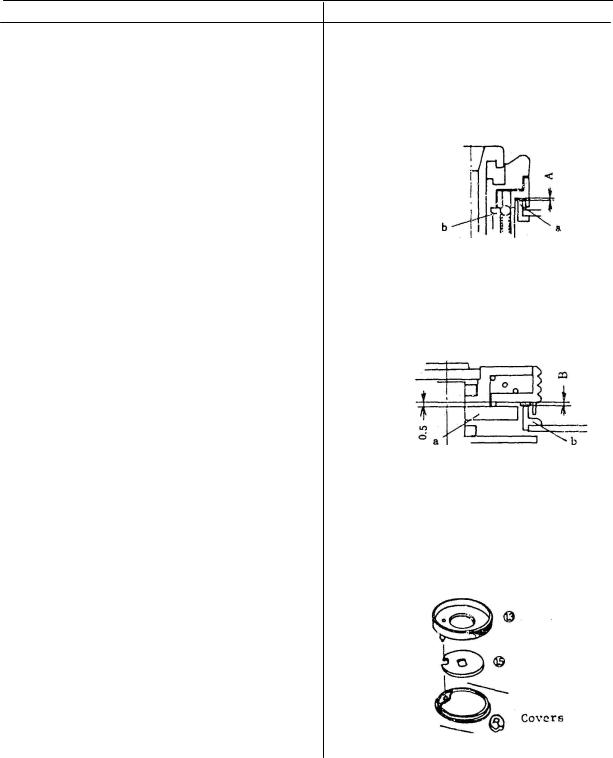
Disassembly Notes |
Assembly and Adjustment Notes |
1.Remove the smooth face screw (3) and shutter button (6) with tool (CY9-6131-000).
|
4. Place teflon washer (8) under the lock lever |
2. Be careful not to lose detent |
(7). Use a washer that is 0.3mm thicker than |
ball (7)-2 inside the camera. |
the "A" dimension shown below. (Water |
|
resistance) |
3.The shutter dial cap (9) is glued in place.
4.Seals (8)(14)(29) and (30) are available in more than one thick ness to insure correct sealing.
5.When the rewind crank (22) is not
installed, don't push the rewind |
A = l.l-(a-b) mm |
|
shaft all the way down into its |
Washer t = A +0.3mm |
|
holder. (If it is, time will be |
|
|
lost in unnecessary work, because |
5. The teflon washer (14) used under the shutter |
|
of the click spring.) |
dial should be 0.1mm thicker than the "B" |
|
|
dimension shown below. (Water resistance) |
|
6. Press the opening safety stopper |
|
|
while removing the left top cover |
|
|
7. (35). |
|
|
|
|
|
Assembly and Adjustment Notes |
|
|
|
|
|
1. Put Diabond into the winding |
B.=0.5-(a-b) |
|
lever shaft hole before final |
||
Washer t = B +0.1mm |
||
installation of the screw (3). |
||
|
||
2. Lubricate the shutter button |
6. When installing the shutter dial, align the notch |
|
shaft (6) and the interior or |
||
in (15) and the pin in the shutter dial ring (13) |
||
the release lock (7) with GE-C9 |
||
with the hole in the top cover. The shutter |
||
[See Water-resistant treatment |
||
must be set to "A" before the dial is installed. |
||
(XIX)]. |
||
|
||
3. Put Lozoid in the detent groove |
|
|
of the release lock (7). |
|
Note: Numbers in parentheses in the text correspond to circled numbers one page 6. Disassemble in normal order and reassemble in reverse order.
Page 7
Canon NEW F-1 Service manual
Assembly and Adjustment Notes
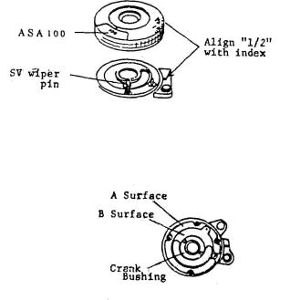
7.Adjust the rewind crank (22) slip torque by changing the friction washer (21). Torque Limits: 35 to 55 gcm.
8.Lubricate both sides of friction spring (20) with PL-015.
9.Hold the rewind fork. Raise the rewind crank knob and turn in the rewind direction. The clutch should engage within one half turn,
10.To install the ASA Dial, set the SV wiper wiper pin as shown and align the "1/2" on the exposure compensation dial with the index.
11.Check the difference in height between the rewind crank bushing and the "A" and "B" surfaces. Install a slightly thinner washer as indicated below.
11.1. Washer (30) "A" Difference Check at four points.
Ex: Difference |
|
Washer "t" |
0.15mm |
--- |
0.1mm |
0.2mm |
--- |
0.2mm |
0.1mm |
--- |
No washer |
11.2. Washer (29) “B” Difference |
|
|
Ex: Difference |
|
Wacher “t” |
0.55mm |
--- |
0.5mm |
0.4mm |
--- |
0.4mm |
0.35mm |
--- |
No washer |
Note: Numbers in parentheses in the text correspond to circled numbers on page 6. Disassemble in normal order and reassemble in reverse order.
Page 8

Canon NEW F-1 Service manual
Assembly and Adjustment Notes
12.SV Brush Adjustment
12.1.Set the SV (ASA.) dial to ASA 6400 -1/3.
12.2.Set the exposure compensation dial at "1".
12.3.Check the position of the brush through the P.C. terminal hole.
Note: Shining the light source (a penlight or the illuminator D or M) through the loupe makes the brush position easier to see.
12.4. Look at the underside of the SV board to check if the brush if the brush is positioned as shown on the ASA 6400 -1/3 pad.
Note: It must stay on the pad at both extremes of dial play.
12.5.Set the dial to ASA 6400 and check that the meter doesn't vary suddenly either up or down.
12.6.If the adjustment is not correct adjust the SV board eccentric.
13.After installing the top cover (35), check the operation of the NORMAL-TIMER-LAMP switch.
It should switch from one function to the next as shown.
Page 9
|
|
Canon NEW F-1 Service manual |
||
|
3. Front panel unit attachment and removal |
|||
|
|
|
|
|
|
Disassembly Notes |
|
Assembly and Adjustment Notes |
|
|
|
|
|
|
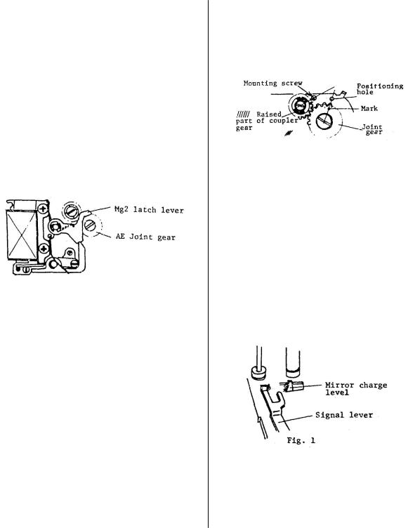
To remove the front panel unit, remove the |
1 AE Joint Gear and AE Coupler |
|||
Installation |
||||
following parts. |
|
|||
|
|
|||
1Remove the top covers, mount apron and bottom cover.
2 Body coverings (front)
3Beeper plate
4 |
Removing the Mg2 latch lever |
1.1 Lubricate the joint gear and |
|
makes the AE joint gear easier |
coupler shafts with Astro-Oil- |
|
to remove. |
MIL-G. |
|
|
|
|
|
1.2 Align the raised portion of |
|
|
the coupler gear with the |
|
|
mounting screw as shown. |
|
|
1.3 Align the mark on the joint |
|
|
gear with the positioning |
|
|
hole as shown. |
|
|
2 Front Panel Unit Installation |
5 |
AE Joint Gear |
2.1 Lubricate the marked parts of the |
|
|
|
|
Position the main diaphragm lever so the |
mirror charge and signal levers (in the |
|
body) with Lozoid. |
|
|
gear can be removed. |
|
|
|
|
6 |
Tripod Socket |
|
7 |
Diaphragm Stricker lever |
|
8 |
Battery Chamber Cover |
|
9Pentaprism rails
10 |
Unsolder eleven leads to main |
|
|
|
circuit board. |
2.2 |
Wind until the curtain edge is |
|
|
|
approximately in the center of |
11 |
X sync contact yellow cord |
|
the frame. |
|
|
2.3 |
In this semi-wound condition, |
12 |
Battery Check contact |
|
do not move the signal lever |
|
|
|
(Fig. 1) or Intermediate signal |
|
|
|
lever (Fig. 4, next page). |
Note: Numbers in parentheses in the text correspond to circled numbers on page 6. Disassemble in normal order and reassemble in reverse order.
Page 10
Canon NEW F-1 Service manual
Disassembly Notes |
Assembly and Adjustment Notes |
||
|
|
||
|
2.4 In the order shown in figure 2, set the |
||
13.If the SV board is to be removed, |
levers as shown in figure 3. |
|
|
remove the white cord from the P.C. |
|
|
|
Terminal. |
|
|
|
If the SV board is not going to be |
|
|
|
removed, lift the front panel and |
|
|
|
unsolder to white cord from the front |
|
|
|
panel (SW16’) end. |
|
|
|
14.Remove the plastic foam light shields |
|
|
|
from the battery box area. |
|
|
|
15.If the moisture seal rubber around the |
|
|
|
main circuit board is damaged, replace |
Fig. 2 |
Fig. 3 |
|
it. |
|||
|
|
||
|
3.1. With the levers positioned as in figure |
||
|
3, install so they are between the mirror |
||
|
charge and signal levers (Fig. 1. page |
||
|
6). |
|
|
Caution: If this operation is not done correctly, winding timing will be incorrect and the shutter will not cock.
3.2. While performing the above step, it is possible that the signal lever will get pushed out of position. Check that the levers are positioned as shown below. (Another method is to hold the intermediate signal lever toward the mount side while installing the unit.)
3.3. While holding the body 1st curtain latch lever out of the way, position the 1st curtain start lever toward the rear.
3.4. Put Arontite R on the threads of the mirror striker lever screw before installing it.
Note: Numbers in parentheses in the text correspond to circled numbers on page 6.
Page 11
Canon NEW F-1 Service manual
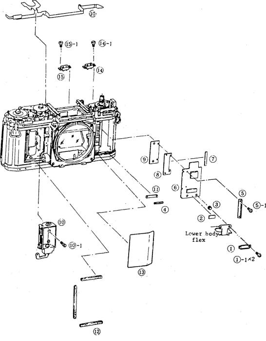
4. Front body
Numbers 1-16
Page 12
Canon NEW F-1 Service manual
Disassembly Notes |
Assembly and Adjustment Notes |
1.To remove the main circuit board (6), the lower body flex must be moved slightly.
2.When the battery cover is removed, temporarily replace the earth (grounding) screw.
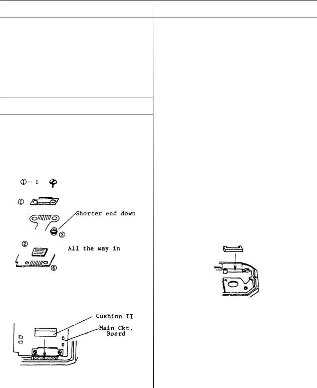
Assembly and Adjustment Notes
1.Apply electrolub to the connector portions of the main circuit board (6) and lower body flex.
2.Clean the elastic connectors (2) and (7) with electrolub.
4.Clean the connector portions of the resistor board (R Board) (9) and main circuit board
(6) (rear side) and apply electrolub.
5.Install the resistor board (9) into the body. Put diabond on the rear of the board around the mounting holes.
6.Battery Chamber Unit (10) Post Installation Checks
6.1.Without a battery installed, the swinging release rod (p/6 the battery chamber unit) must overlap the release pin below it by at least 1/2 the pin diameter.
6.2.When the minus contact of the battery box is pressed down and then released slowly, the
rod must return completely and smoothly.
7.Install cushion I (11) as shown below. Push it in until it is flush against the main circuit board and diabond it to the body.
3. Install cushion II (4) as shown below.
Note: Numbers in parentheses in the text correspond to circled numbers on page 12. Disassemble in normal order and reassemble in reverse order.
Page 13
Canon NEW F-1 Service manual
Assembly and Adjustment Notes
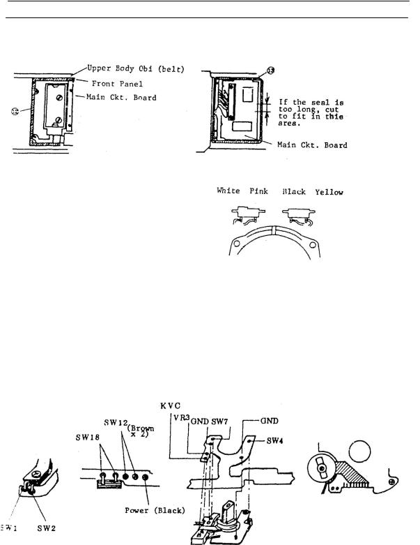
8.Attach the light shield (12) and seal (13) as shown.
9.Pentaprism Contact Installation
9.1.Don't interchange the position of the left and right contacts, or reverse either of them.
9.2.Solder the leads as quickly as possible. Excessive heat will loosen the contact pins.
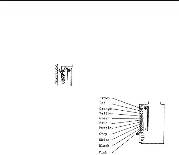
10.Main Flex Installation
10.1.Solder the main flex (16) at the following positions.
10.2.To prevent the main flex from interfering with the top cover screw holes, fix it with double-sided tape.
10.3.The brown leads to SW12 are interchangeable.
See section 9 (Upper Body) for the correct bending of the flex.
Note: Numbers in parentheses in the text correspond to circled numbers on page 12. Disassemble in normal order and reassemble in reverse order.
Page 14
Canon NEW F-1 Service manual
Assembly and Adjustment Notes
11.Front Panel Lead Soldering
11.1.Put flux on the main circuit board solder lands.
11.2.Solder from the bottom up.
11.3.Dress extra lead toward the bottom as shown.
Note: The thick white lead goes to the
P.C. terminal.
Note: Numbers in parentheses in the text correspond to circled numbers on page 12. Disassemble in normal order and reassemble in reverse order.
Page 15

Canon NEW F-1 Service manual
5. Upper Body (Winding side)
(6) can be displaced without removing (1) - (5)
Page 16
Canon NEW F-1 Service manual
Disassembly Note |
Assembly and Adjustment Notes |
||
|
|
|
|
1. |
Shutter Speed Selector |
|
|
|
|
1. The shutter speed selector (6) TV double |
|
1.1. To remove the shutter speed selector |
brushes must be aligned both vertically |
||
|
(6), unsolder the black lead from SW4 |
and radially, so they will both make |
|
|
and remove four screws [(6)-1 x 2 and |
contact with the correct pad. |
|
|
(6)-2 x 2]. |
|
|
|
|
2. Clean the TV resistor board (2) and install |
|
Notes: |
it so that break in the pattern is at the |
||
|
|
upper right with the shutter at "A". |
|
1. |
One of the (6)-1 screws is partially |
|
|
|
hidden by flex (5) and hard to remove. |
Pattern break |
|
2. |
Be careful not to damage the main flex. |
|
|
1.2 To remove the selector (6) completely, unsolder the black and brown leads and disengage the tungsten cable.
1.3To temporarily remove (6) without |
3. Shutter Speed Selector (6) |
|
|
||
|
removing the tungsten cable: |
3.1 Installation |
|
|
|
1) |
Set the shutter to the "B" position and |
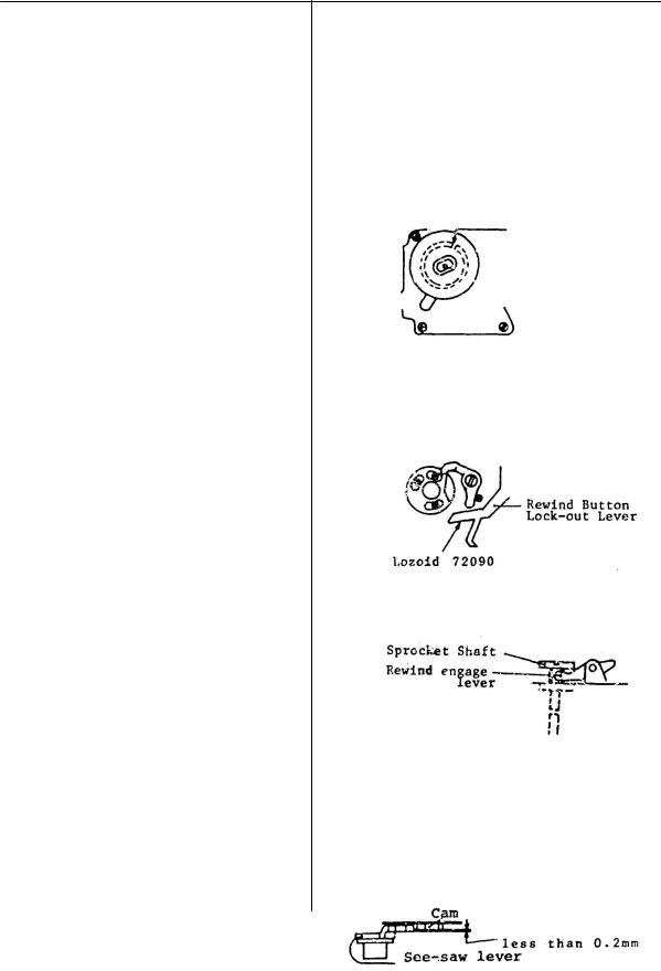
1) Lubricate the (Upper) Rewind button lock- |
|
remove the screws. Carefully lift the |
|
|
out lever with Lozoid 72090. |
|
|
selector off. |
|
|
|
|
2) |
Place the selector out of the way but |
|
|
where the cable will remain taut and |
|
|
not become kinked. |
|
2.Mounting screw (9)-2 for the winding base is under main switch (8).
3.The entire 2nd curtain brake assembly (17) can be removed without disassembling it by removing three screws (15) and collar (16). Disengage the brake lever from the
master gear and (17) can be removed.
3.2 Post-Installation Checks
1) Check that the see-saw lever works smoothly.
2) There should be less than 0.2mm difference in the height of the fixed cam and see-saw lever.
Page 17
Canon NEW F-1 Service manual
Assembly and Adjustinent Notes
4.Winding Unit (9) Installation
4.1.Lubricate the winding coupler joint with MIL-G.
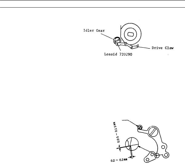
4.2.Lubricate the friction surfaces of the idler gear and frame counter drive claw with Lozoid 72090.
4.3.Install with the frame counter drive claw pulled out of the way.
5.Put a little Arontite L in the Key screw (10) hole in the sprocket shaft (12) and install the screw.
6.2nd Curtain Cam Follower (13)-3 Installation
6.1.In the wound condition, the gap between the 2nd Curtain Cam Follower and the hook should be 0.05 to 0.15mm. Adjustment: The follower is available in several sizes.
6.2.Lubricate the pivot shaft with astro-oil.
6.3.The end play of the follower should be less
than 0.15mm, and it must return by the spring pressure.
6.4.The mesh of the follower and the hook should be 0.2 to 0.3mm. Adjustment: Eccentric
6.5.Lubricate the mesh surfaces of the follower and hook with astro-oil.
7.2nd Curtain Release Lever
7.1.Lubricate the shaft with astro-oil.
7.2.Thrust play should be under 0.05mm and end play under 0.2mm. Use washers to adjust the play.
8.2nd Curtain Brake Assembly (17)
8.1.While holding the brake lever out of the way (toward the prism rails), slip the brake assembly (17) into place under the master gear.
8.2.Tighten the screws starting with the one at the front (mount) side.
Note: Numbers in parentheses in the text correspond to circled numbers on page 16. Disassemble in normal order and reassemble in reverse order.
Page 18
Canon NEW F-1 Service manual
6. Tungsten cable adjustment
Assembly and Adjustment Notes
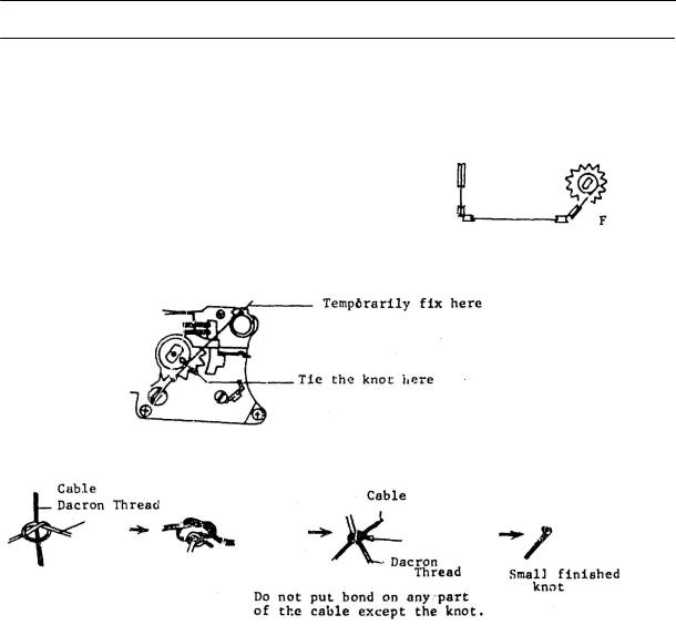
1.Put the knotted end of the cable into the slot in the indicator pulley. Charge the pulley one revolution and temporarily install a pin to hold it.
2.Check that the cable lies correctly in the pulley.
3. Set the shutter dial at "B". |
Information |
|
pulley |
4.Thread the cable as shown in figure 1.
5.Remove the pin from the indicator pulley and find the spot
where the "B" appears in the finder. Temporarily fix the end as shown in figure 2. At the point on the shutter dial pulley where the slot is a very small knot must now be formed.
6. Tie the knot as shown below.
7.Insert the knot into the slot.
8.Put cyanobond on the knot slot. Do not get bond on the cable or in the pulley groove.
9.Check the entire range of shutter speeds. If they are not correctly aligned in the information window, adjust the nut on, the information pulley vertically until they are. After adjustment, stake the nut with black diabond.
10.Check that the right-side viewfinder information disappears when the dial is moved from 1/2000 to "A".
Check that the right-side viewfinder information appears when the dial is moved from "A" to 1/2000 and remains visible through the entire shutter-speed range from 1/2000 to "B".
Page 19
Canon NEW F-1 Service manual
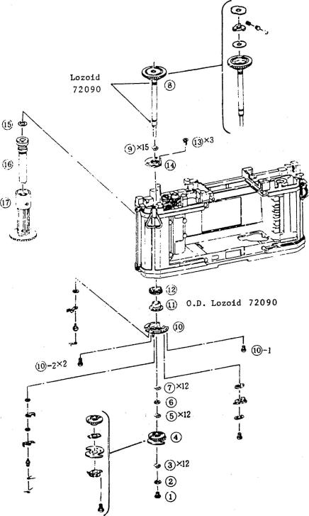
7. Spool
Steel Balls 3,5,7,9 Lozoid 72090
Page 20
Canon NEW F-1 Service manual
Disassembly Notes
Be careful not to loose any of the bearing balls inside the camera. (See the facing page for the number of balls in each location.)
Assembly and adjustment
1.Winding Coupler (4)
1.1 With the shutter completely wound {winding stopper engaged) , the winding coupler should be positioned as shown (10° ± 4.5° off the body centerline).
1.2 Visual angle check: the: line formed by the axis of the winding shaft and the mounting screw for SW5 is the maximum limit (14.5°) for the coupler.
2.Spool Torque
2.1Lubricate the spool unit fiber friction washers with a mixture of FLA and PO A2 grease. (7:3)
2.2Exercise the spool mechanism 30 to 50 times. Then measure the torque. Std: 110 - 150 gcm
3.Post Assembly Checks
3.1After the spool unit is installed in the camera the correct tension measured at the spool circumference (equivalent to spool friction torque) 170 to 230g.
3.2Adjust the thrust play to 0.1 to 0.3mm by changing washer (15).
4.Adjust winding shaft thrust play to 0.05 to 0.15mm by changing washer (2).
Note: Numbers in parentheses in the text correspond to circled numbers on page 20. Disassemble in normal order and reassemble in reverse order.
Page 21
Canon NEW F-1 Service manual
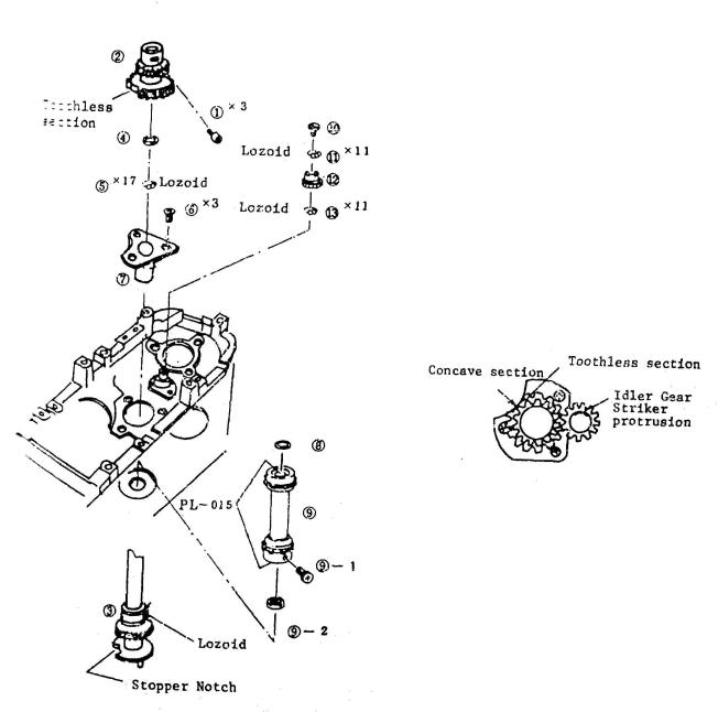
8. Sprocket
Assembly and adjustment notes
1. Lubricate the upper and lower sprocket bushings with PL-015.
2. Adjust thrust play to 0.1 to 0.2mmm with washer (8).
3. Align the toothless section of the main gear with the stopper notch in the sprocket shaft (3)
4. Adjust thrust play of the main gear to 0.03 to 0.15mm by-
washer (4).
5. Align the main gear (2) and idler gear (12) as shown below and mesh them.
The protuding striker section should be as shown ±2 teeth.
Lozoid: Loroid 72090
Page 22

Canon NEW F-1 Service manual
9. Checks and adjustments
Assembly and Adjustment Notes
1.Shutter Curtains Installation
1.1.In the wound condition, the leading edge of the 2nd curtain should be from 5.4 to 5.9mm from the edge of the film aperture.
1.2.The leading edge should be parallel with the edge within 0.2mm.
1.3.In the wound condition, the trailing edge of the 1st curtain should overlap the leading edge of the 2nd curtain by 2.0 to 2.5mm, and this overlap should be maintained throughout the winding cycle.
1.4.The edge of the 1st curtain should be parallel with the edge of the 2nd curtain within 0.2mm.
Note: The 2nd curtain "minus latch" should not latched at the full wound (5.4 - 5.9mm) position.
2. 1st Curtain Brake
2.1.Check
1)From the maximum curtain travel position* to the fully wound condition, the ratchet should move from the start position to the middle of the third tooth.
2) Even if the brake lever is pushed in the direction to the end of its travel the ratchet should not go to the 4th tooth,
* Maximum curtain travel position: The curtains usually stop slightly short of this position because of the brakes. For accurate checks, they can be pushed to the maximum with the master gear.
Page 23
Canon NEW F-1 Service manual
Assembly and Adjustment Notes
2.2.1st Curtain Brake Adjustment
From the maximum curtain travel position, wind, release the shutter with the seesaw lever at "B", and check the difference in the position where the curtain stops and the maximum curtain travel position. It should be no more than half- a-tooth on the master gear.
1)To increase brake torque, turn the nut CW, but don't overtighten it. When you reach the point where it starts to get tight, back off 90°.
2)To veaken torque, turn the nut CCW, but don't turn it too far. It should not be high enough to touch the cam follower at the maximum follower play.
3)If the adjustment cannot be made with the nut, three different diameters (strengths) of the coil spring are available (0.6, 0.65 and 0.7mm dia.).
4)After adjustment apply diabond to the nut. Do not use enough to increase the height of the nut.
3.2nd Curtain Brake
3.1Adjustment
1)Standard: 0 to 0.5 teeth (master gear) Check as explained in 2.2 above. The nut must not exceed the height of the shutter speed selector base.
2)Other adjustments are identical to the 1st curtain brake adjustment.
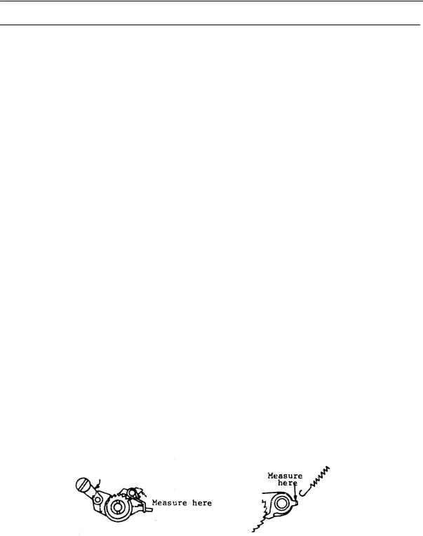
3.2Brake Torque Check (Reference)
Measure the tension at the ratchet pawl as indicated.
1st Curatin Brake: About |
2nd Curtain Brake |
800g |
(with return spring disengaged) |
Page 24
Canon NEW F-1 Service manual
Adjustment Notes
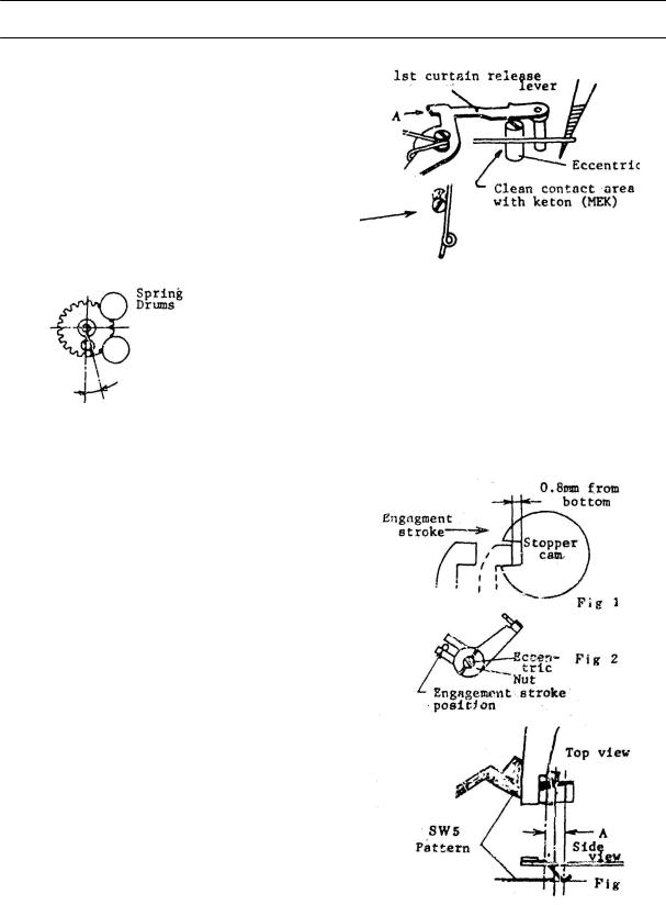
4. SW4 OFF Timing
4.1Clean the contact surface with keton.
4.2Slowly push the 1st curtain release lever in the "A" direction and note where the latch is released. Adjust the switch with the eccentric so that SW4 goes off at 0.1 to 0.2mm additional travel.
4.3The eccentric should be adjusted so that longer side is toward the rear.
5. Dowel Gear Position
At the maximum curtain travel position, and with the camera mount toward you, the dowel should be within 0.5 teeth left to 1 tooth right of the centerline.
6. SW5 Timing
6.1Switching Position
At a point 0.8mm from the bottom of the stopper notch on the engagement stroke of the stopper claw, SW5 should switch on.
1)Make sure that the stopper is not 0.8mm
from the bottom of the disengagement stroke.
2)Check the position of the drive pin. It is different from engagement and disengagement.
3)Do not forget to retighten the nut after adjustment.
6.2As a visual check of the SW5 brush position the edge of the pattern should be located approximately under the midpoint of the slope "A" of the brush.
6.3In the wound condition, SW5 must be off and turn on during winding.
6.4After the check is finished, stake the nut with diabond.
Page 25
Canon NEW F-1 Service manual
Adjustment Notes
7. Mechanical Release Stroke Adjustment
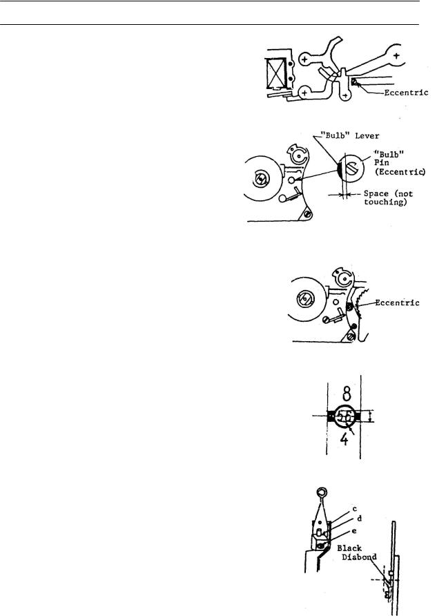
The shutter should release at 1.4±0.15mm of the shutter button stroke. Adjust with the eccentric.
8. "Bulb" Pin Adjustment
Adjust so that at 1.25mm of the shutter button stroke the
"bulb" pin and "bulb" lever are not touching.
9. Rewind Button Release Stroke Adjustment
9.1Close the back cover. Set the rewind (R) button.
9.2Adjust the eccentric so that the R button is released at 1.0±(0.2mm of the shutter button stroke.
9.3Check that the sprocket is free and turns smoothly when the R button is set.
10. Following Needle Position
10.1Mount the "tool standard" lens and set the diaphragm at f/5.6.
10.2 |
Limit: A line "a" through the center of the following must |
fall |
|
on the f/stop number (dimension "b"). The height of the |
|
|
f/stop numbers is equal to 0.6 f/stops. |
|
10.3 |
There must be approximately the width of the following |
|
|
needle ring clearance between the outer edge of the |
|
|
needle circle and the edge of the aperture scale make. |
|
10.4 |
After adjustment, apply a small amount of cyanobond at |
|
|
"c", "d" and "e". |
|
10.5 |
Apply diabond to the root of the needle. |
|
Page 26
Canon NEW F-1 Service manual
Adjustment Notes
11. Mechanical Shutter
11.1Curtain Travel Time
1)Standard: 7.5±0.2ms (1/1000)(34mm slit spacing).
2)Adjustment: Spring Drum Gear
11.2Shutter Speed (Exposure Time)
1)Adjust at 1/250 using the 2nd Curtain Release Lever (Seesaw Lever) Turning the seesaw eccentric CW increases shutter speed.
2)Adjust 1/2000 with the 2nd curtain cam follower.
3)Adjust repeating steps 1 and 2 until the best balance of all speeds is obtained.
4) Shutter Accuracy (measured in EV) |
Faster |
1/2000, 1/1000: ±0.4EV 1/500 - 8 sec : ±0.2EV
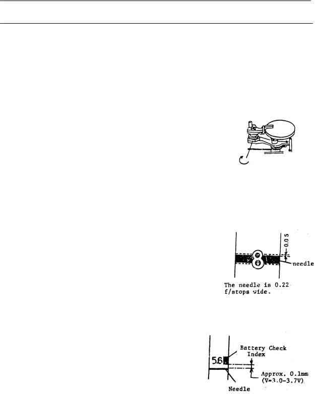
12. Meter Position Adjustment
12.1Connect a 10kohm variable resistor and microammeter in series to the + side of the power supply set to about 2V. Adjust the resistor for a current flow of 459uA through the meter.
12.2Adjust the meter housing position so that the meter needle is centered on the "8" ±0.05mm.
12.3Adjust the current and check the following positions:
12.4Bond the meter housing to the die casting with black diabond. (Do not leave any strings of bond.)
13. Battery Check and Low voltage Interlock1
13.1Reduce the power supply voltage until the top of the meter needle is about 0.1mm below the bottom of the battery check index. At this point check that the applied voltage is from 3.0 to 3.7 volts.
13.2Check that the low voltage interlock activates at 3.2 volts.
Note: 1. Low voltage interlock is the voltage where shutter release is prevented by the cameras program.
Page 27
Canon NEW F-1 Service manual
Adjustment Notes
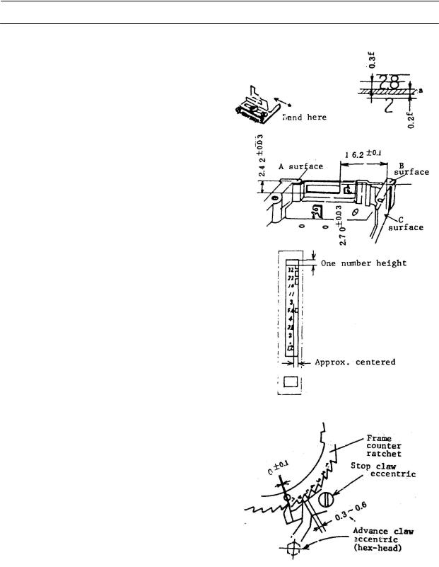
14. Maximum Aperture (AVO) Indicator
14.1Set AVO= 2.8 (Max. Aperture Pin Height = 6.9±0.03mm)
14.2Bend the lever (dwg.) so that the top of the red mark is positioned within the hatched area.
14.3Check other maximum apertures. They should also fall within 0.3 to 0.5f of the same position.
15.Aperture Mask Installation and Adjustment
15.1The distance from the "A" surface to the bottom of the mask opening is 2.42±0.03mm.
15.2The distance from the "B" surface to the bottom edge of the shutter speed opening is 2.70±0.03mm.
15.3The distance from the C surface to the f/1.2 end of the aperture scale mask aperture is 16.2±0.1mm. When the mask is correctly positioned, bond it with diabond.
15.4To position the aperture scale film, install the film with diabond, install the prism and position the film before the bond hardens.
16.Frame Counter Adjustment
16.1With the frame counter in the returned position, the stop claw should be engaged and flush against the 7th tooth ±0.1 Adjust with the eccentric.
16.2Adjust the advance claw with the hex-head eccentric so the tip of the claw is 0.3 to 0.6mm up the slope of the 5th ratchet tooth.
16.3When the advance claw is at maximum stroke, adjust so that the clearance of the stop claw is 0.2 to 0.4mm.
Page 28
Canon NEW F-1 Service manual
Adjustment Notes
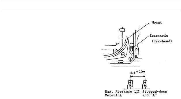
17.Following Needle Hidden Position
17.1Activate the stop-down lever, with the lens on or off of "A", the following needle must not be visible.
17.2Push the stop-down lever back into the normal position. With the lens off of "A" the following needle is visible. It must disappear when the lens is set to "A".
17.3Adjust the hex-head eccentric (dwg.) to meet these requirements.
17.4Following Needle Movement (Reference)
18.Release Stroke and Pressure (Checks)
18.1 Mechanical Release (without battery)
Shutter button protrusion |
: |
1.0±0.2mm (Std: Shutter Ring) |
|
Release Stroke |
: |
1.4±0.2mm |
|
Total Stroke |
: |
1.7±0.1mm |
|
Release pressure |
: |
Under 1,000 g |
|
18.2 Electromagnetic Release |
|
|
|
SW 1 ON |
: |
0.8+0.2mm |
|
SW 2 ON |
: |
1.4±0.2mm |
|
SW 1 - SW 2 Separation |
: |
At least 0.5mm |
|
Total Stroke |
: |
1.7±0.lmm |
|
SW 1 Pressure |
: |
100±20 q |
(except when R button |
SW 2 Pressure |
: |
350±50 g |
set or at "B") |
Page 29
Canon NEW F-1 Service manual
Adjustment Notes
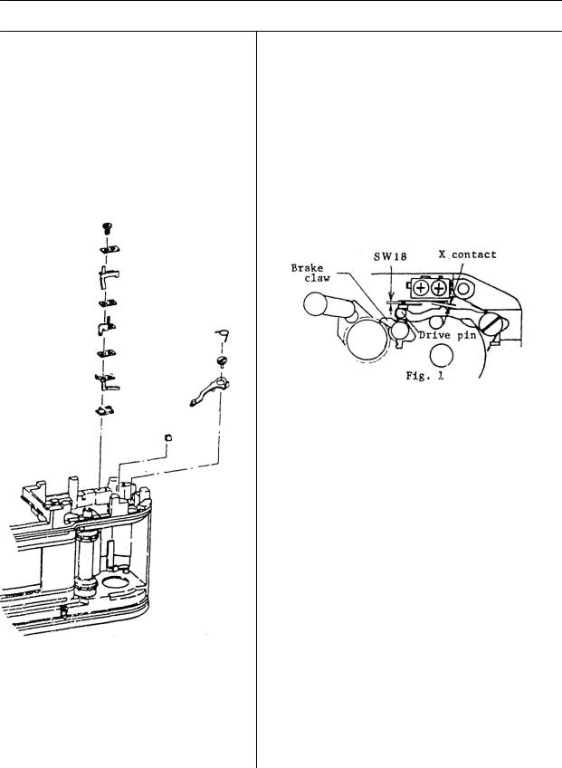
19. SW 18, X Sync Check and Adjustment |
19.1 X Contact Check |
When winding from the maximum curtain travel position (MCTP), the contact separation is 0.3mm when the brake claw is on the third ratchet tooth.
Also, when winding from the MCTP, the contact drive dowel must have at least 0.5mm total travel.
19.2 SW 18 Check and Adjustment
1) While winding slowly from the MCTP, adjust so that SW 18 turns on when the brake claw has traveled 2 to 2.5 teeth. Adjust by bending the fixed contact.
2) (Visual Check)
With the brake claw at the third tooth, check that there is at least 0.2mm separation between the drive pin and the switch lever.
3) Apply TUFFY TF-1156 to the marked areas in figure 1.
Page 30
 Loading...