


Video Product
DMC III
MECHANICAL
CHASSIS
ENGLISH EDITION
c CANON INC. 2003
Canon Inc.
Digital Imaging Products Service Dept.
First Edition : Feb. 2003
First Print : Feb. 2003

CHAPTER 1. OPERATION
CONTENTS
1. Outline ----------------------------------------------------------------------------------------------------------------------------------------- |
|
|
2-1 |
|
1-1 Configuration Comparison of DMC II and DMC III |
----------------------------------------------------------------------------- 2-1 |
|||
1-2 |
DMC III Slide in/out Status --------------------------------------------------------------------------------------------------------- |
2-2 |
||
1-3 Mechanical Modes and Mode Switches-------------------------------------------------------------------------------------------- |
2-3 |
|||
2. Operation --------------------------------------------------------------------------------------------------------------------------------------- |
|
|
2-4 |
|
2-1 |
Main Mechanical Parts --------------------------------------------------------------------------------------------------------------- |
2-4 |
||
|
2-1-1 Nomenclatures -------------------------------------------------------------------------------------------------------------- |
2-4 |
||
2-2 |
Operation of Main Parts -------------------------------------------------------------------------------------------------------------- |
2-5 |
||
|
2-2-1 |
Gear Train |
------------------------------------------------------------------------------------------------------------------- |
2-5 |
|
2-2-2 Reel Hub Drive ------------------------------------------------------------------------------------------------------------- |
2-6 |
||
|
2-2-3 Loading Operation of Tape Guide Base --------------------------------------------------------------------------------- |
2-7 |
||
|
2-2-4 |
Tape Path -------------------------------------------------------------------------------------------------------------------- |
|
2-8 |
2-3 |
Mechanical Parts in Mode Transition ---------------------------------------------------------------------------------------------- |
2-9 |
||
|
2-3-1 |
Cassette-In → Cassette-Down -------------------------------------------------------------------------------------------- |
2-9 |
|
|
2-3-2 |
Loading-1 |
(Tape Detection R with Tape) ------------------------------------------------------------------------------ |
2-10 |
|
2-3-3 |
Loading-2 |
(without Tape) ------------------------------------------------------------------------------------------------ |
2-11 |
|
2-3-4 Loading-3 |
(with Tape/BOT) --------------------------------------------------------------------------------------------- |
2-12 |
|
|
2-3-5 |
Loading-4 |
(Blank Search-1) --------------------------------------------------------------------------------------------- |
2-13 |
|
2-3-6 |
Loading-5 |
(Blank Search-2) --------------------------------------------------------------------------------------------- |
2-14 |
|
2-3-7 |
Loading-6 |
(Blank Search-3) --------------------------------------------------------------------------------------------- |
2-15 |
|
2-3-8 |
Loading-7 |
(Blank Search-4) --------------------------------------------------------------------------------------------- |
2-16 |
|
2-3-9 STOP → PLAY ------------------------------------------------------------------------------------------------------------ |
2-17 |
||
|
2-3-10 STOP → FF -------------------------------------------------------------------------------------------------------------- |
2-18 |
||
|
2-3-11 STOP → REW ----------------------------------------------------------------------------------------------------------- |
2-19 |
||
|
2-3-12 PLAY → CUE ----------------------------------------------------------------------------------------------------------- |
2-20 |
||
|
2-3-13 PLAY → REV ----------------------------------------------------------------------------------------------------------- |
2-21 |
||
|
2-3-14 PLAY → STILL --------------------------------------------------------------------------------------------------------- |
2-22 |
||
|
2-3-15 EJECT (with tape) ------------------------------------------------------------------------------------------------------- |
2-23 |
||
|
2-3-16 EJECT (without tape) --------------------------------------------------------------------------------------------------- |
2-24 |
||
DMC III
CHAPTER 1. OPERATION
1. Outline
DMC III is a digital video mechanical chassis which has been developed newly to enhance competitiveness in cost and reliability.
|
|
Digital Mechanism Chassis |
|
|
|
DMC III |
DMC II |
Drum Diameter |
|
21.7 mm |
21.7 mm |
Slide |
|
● |
● |
Size |
Depth |
56 mm |
56 mm |
|
Width |
72 mm |
72 mm |
|
Height |
23. 7 mm |
22.2 mm |
Volume |
|
95 cc |
89 cc |
Weight |
|
100 g |
100 g |
Number of Parts |
|
194 |
272 |
FF/REW Speed |
|
30 × |
30 × |
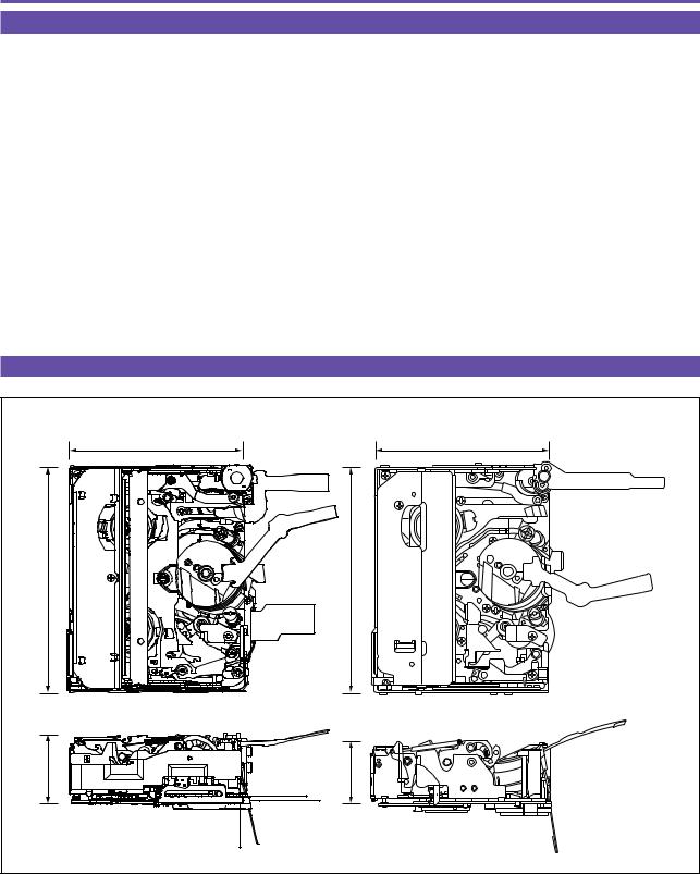
1-1 Configuration Comparison of DMC II and DMC III
DMC III |
DMC II |
56mm |
56mm |
72mm |
72mm |
23.7mm |
22.2mm |
|
Fig. 1-1 |
1-1

DMC III
CHAPTER 1. OPERATION
1-2 DMC III Slide in/out Status
Slide in status |
Slide out status |
23.7mm |
39.4mm |
56mm |
73mm |
|
Fig. 1-2 |
1-2

DMC III
CHAPTER 1. OPERATION
1-3 Mechanical Modes and Mode Switches
|
EJECT |
STAND-BY |
LD1 |
LD2 |
STOP |
PLAY/REV |
Resistance KΩ (COM to 2 ) |
18 |
36 |
54 |
72 |
90 |
0 |
T Main Brake |
OFF |
OFF |
OFF |
OFF |
ON |
OFF |
TB UNIT |
OFF |
OFF |
OFF |
OFF |
OFF |
OFF/ON |
S Main Brake |
OFF |
OFF |
OFF |
OFF |
ON |
OFF |
S Soft Brake |
ON |
ON |
ON |
ON |
OFF |
OFF |
Pinch Roller |
OFF |
OFF |
OFF |
OFF |
OFF |
ON |
COM |
|
|
1 |
0 |
STOP |
|
18KΩ |
|
2 |
1 |
LD2 |
|
18KΩ |
|
|
2 |
LD1 |
|
18KΩ |
|
|
3 |
STAND-BY |
|
18KΩ |
|
|
4 |
EJECT |
|
18KΩ |
|
|
5 |
PB |
0 |
|
|
5 |
|
|
|
1 |
|
4 |
|
|
2 |
|
|
3 |
|
|
Fig. 1-3 |
|
|
1-3
DMC III
CHAPTER 1. OPERATION
2. Operation
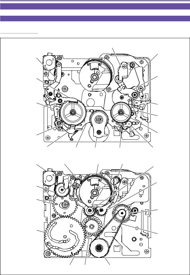
2-1 Main Mechanical Parts
2-1-1 Nomenclatures
Capstan Motor
Review Arm Ass'y
Tension Arm Ass'y
Tension Brake Ass'y |
Pinch Roller Ass'y |
|
|
Main S Brake |
Eject Lever |
|
|
|
Pinch Push Lever |
T Reel Ass'y
S Reel Ass'y
Soft S Brake |
Slide Main |
Idler |
Main T Brake |
TB Unit |
Loading Motor Ass'y |
S Guide Roller Ass'y |
Drum Unit |
T Guide Roller Ass'y |
S Loading Gear |
|
|
|
||
|
|
|
|
|
Wheel Gear |
|
|
|
T Loading Gear |
|
|
|
|
|
Mode Switch Gear |
|
|
|
|
|
|
|
|
Capstan Gear |
Main Cam Gear
Timing Belt
Cam Lever Connect Gear Pulley Gear
Fig. 1-4
1-4
DMC III
CHAPTER 1. OPERATION
2-2 Operation of Main Parts
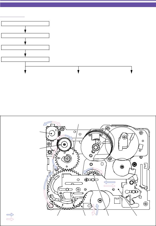
2-2-1 Gear Train
Loading Motor (1) rotates.
Wheel Gear (2) rotates.
Mode Switch Gear (3) rotates.
Main Cam Gear (4) rotates.
Cam Lever (5) turns. |
|
Connect Gear (6) rotates. |
|
Slide Main (7) moves. |
|
|
|
|
|
Mode Switch Gear (3)
Loading Motor (1) 
Wheel Gear (2) 
LOADING |
Main Cam Gear (4) |
Cam (5) |
Connect Gear (6) |
Slide Main(7) |
|
UNLOADING |
|||||
|
|
|
|
Fig. 1-5
1-5

DMC III
CHAPTER 1. OPERATION
2-2-2 Reel Hub Drive
Capstan Motor (1) rotates.
Capstan Gear (2) rotates.
Pulley Gear (4) is rotated by Timing Belt (3).
Idler (5) turns to engage
with T Reel Ass'y (6) or S Reel Ass'y (7).
T Reel Ass'y (6) or S Reel Ass'y (7) rotates.
Capstan Motor (1)
Capstan Gear (2)
Timing Belt (3)
S Reel Ass'y(7)
 T Reel Ass'y(6)
T Reel Drive |
Idler (5) |
Pulley Gear (4) |
S Reel Drive |
|
|
|
|
|
|
Fig. 1-6 |
|
1-6

DMC III
CHAPTER 1. OPERATION
2-2-3 Loading Operation of Tape Guide Base
Connect Gear (1) rotates.
S Loading Gear (2) rotates.
T Loading Gear (4) rotates.
S Guide Roller Ass'y (3) slides.
Caught by Drum Base (6).
T Guide Roller Ass'y (5) slides.
Caught by Drum Base (6).
S Guide Roller Ass'y (3) |
Drum Base (6) |
TGuide Roller Ass'y (5) |
S Loading Gear (2)
LOADING
Connect Gear (1) T Loading Gear (4)
UNLOADING
Fig. 1-7
1-7
DMC III
CHAPTER 1. OPERATION


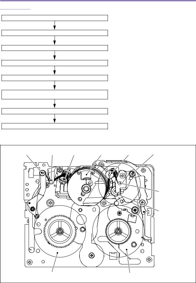
 Tape Path
Tape is drawn out of S Reel (1).
Tape is tensioned by Tension Post (2).
Direction of tape is changed by P2 and P3 Posts (3), (4).
Tape runs around Drum Unit (5).
Direction of tape is changed by P5 Post (6).
Pinch Roller (8) is pressed against
Capstan Shaft (7) to feed tape.
Tape runs through P7 Post (9).
Tape is taken up by T Reel (10).
Tension Post (2) |
P2 Post (3) P3 Post (4) Drum Unit (5) |
P5 Post (6) |
P7 Post (9) |
Capstan Shaft (7)
Pinch Roller (8)
S Reel (1) |
T Reel (10) |
Fig. 1-8
1-8
DMC III
CHAPTER 1. OPERATION
2-3 Mechanical Parts in Mode Transition
2-3-1 Cassette-In → Cassette-Down
Insert cassette.
Cassette lid lock is released by Cassette Compartment Claw (2).
This makes Cassette Lid (5) free to open/close.
Press Cassette Compartment (1) in arrow direction (downward).
Lock Lever (3) moves along Lock Guide (4). |
|
Cassette Lid (5) opens. |
|
|
|
|
|
|
|
|
|
Lock Lever (3) turns in arrow direction.
Lock Cassette Compartment (1). |
|
Eject Lever (6) turns. |
|
|
|
|
|
|
|
|
|
Cassette-in Switch (7) is turned ON.
Lock Lever (3) Cassette Compartment Claw (2)
Cassette Compartment (1)
Cassette Lid (5)
EJECT Lever (6)
Lock Lever (3)
Lock Guide (4)
EJECT Lever (6)
Cassette-in Switch (7)
Fig. 1-9
1-9
DMC III
CHAPTER 1. OPERATION
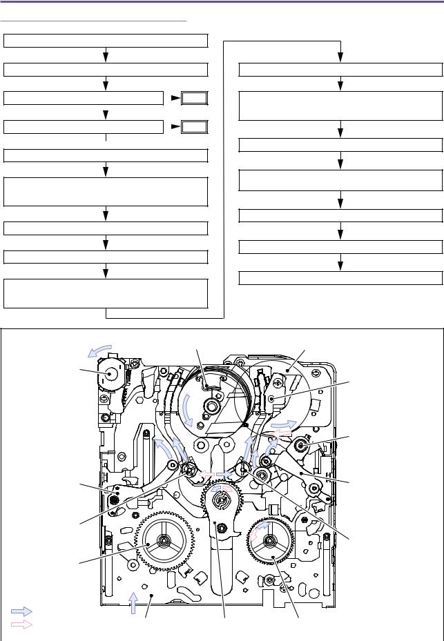
2-3-2 Loading-1 (Tape Detection R with Tape)
Push down Cassette Compartment.
Cassette-in Switch turns ON.
Whether tape exists is detected. |
|
A |
|
|
|||
|
No |
Yes |
|
|
|
|
|
Slide Chassis (6) slides.
Tension Arm Ass'y (7), S Guide Roller Ass'y (8), T Guide Roller Ass'y (9), Pinch Arm Ass'y (10) and Review Arm Ass'y (11) move to take up tape.
Beginning of tape is detected. |
|
B |
|
Yes
 No
No
Drum Unit (1) rotates.
Capstan Motor (2) rotates counterclockwise (forward, 3× speed, 0.3 sec), and Idler (3)
turns to engage with T Reel Ass'y (4) for taking up tape.
Capstan Motor (2) stops.
Loading Motor (5) rotates counterclockwise.
Capstan Motor (2) rotates clockwise (reversely, unit speed, 0.45 sec), and Idler (3)
turns to come into contact with Stopper of Reel Cover.
Slide Chassis (6) stops moving.
Pinch Arm Ass'y (10) is pressed against Capstan Shaft (13)
PLAY Position is detected.
Loading Motor (5) stops rotating.
To "Blank Search".
Drum Unit (1) |
Capstan Motor (2) |
Loading Motor (5)
Capstan Shaft (13)
Tension Arm
Ass'y(7)
S Guide Roller
Ass'y(8)
S Reel Ass'y(12)
Pinch Arm Ass'y(10) |
Review ArmAss'y(11) |
TGuide Roller Ass'y(9) |
LOADING T |
|
|
|
LOADING S |
Slide Chassis (6) |
Idler (3) |
T Reel Ass'y(4) |
|
|
|
|
|
|
Fig. 1-10 |
|
1-10
DMC III
CHAPTER 1. OPERATION
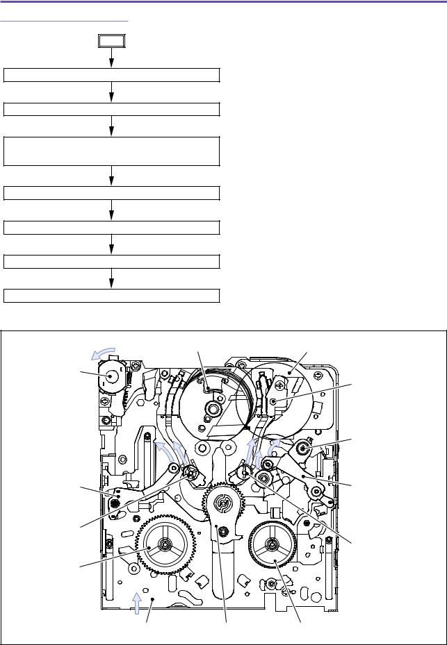
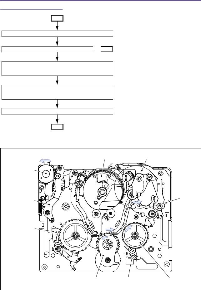
2-3-3 Loading-2 (without Tape)
A
Loading Motor (5) rotates counterclockwise.
Slide Chassis (6) slides.
Tension Arm Ass'y (7), S Guide Roller Ass'y (8), T Guide Roller Ass'y (9), Pinch Arm Ass'y (10) and Review Arm Ass'y (11) move.
Slide Chassis (6) stops moving.
STOP Position is detected.
Loading Motor (5) stops rotating.
Standby at STOP status.
Loading Motor (5)
Tension Arm
Ass'y(7)
S Guide Roller
Ass'y(8)
S Reel Ass'y(12)
Drum Unit (1) |
Capstan Motor (2) |
Capstan Shaft (13)
Pinch Arm Ass'y(10) |
Review ArmAss'y(11) |
TGuide Roller Ass'y(9) |
Slide Chassis (6) |
Idler (3) |
T Reel Ass'y(4) |
Fig. 1-11
1-11
DMC III CHAPTER 1. OPERATION
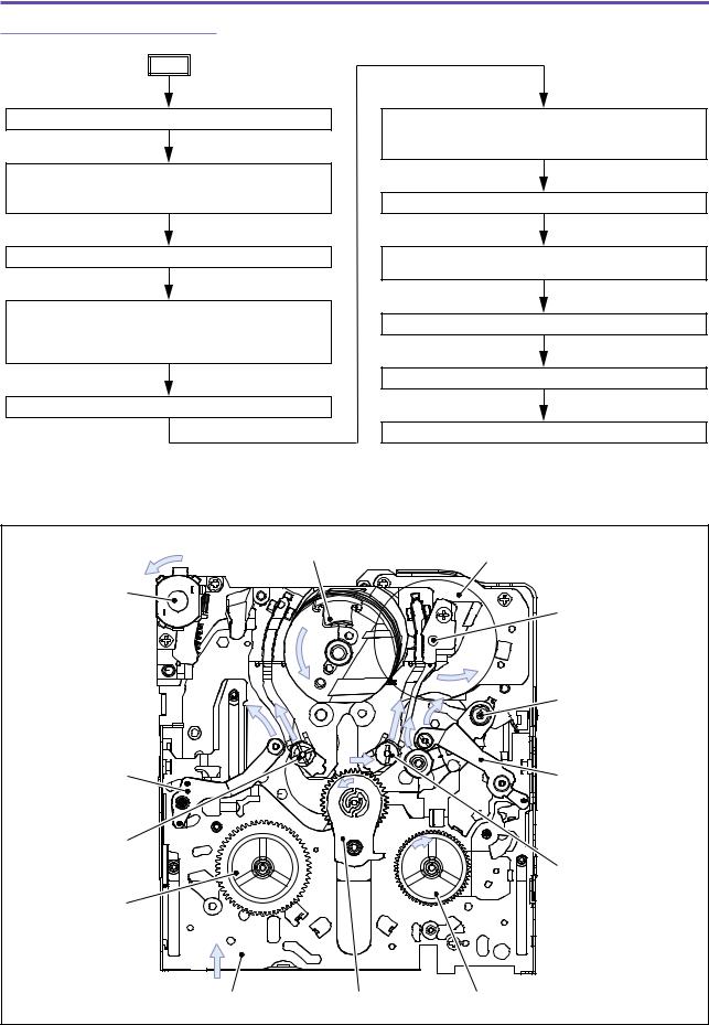
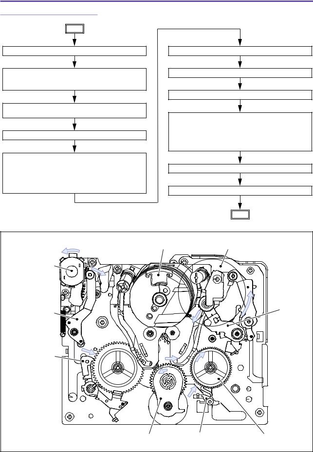
2-3-4 Loading-3 (with Tape/BOT)
B
Drum Unit (1) rotates.
Capstan Motor (2) rotates counterclockwise (forward, 3× speed, 0.3 sec), Idler (3) turns to engage with T Reel Ass'y (4) for taking up tape.
Capstan Motor (2) stops.
Capstan Motor (2) rotates counterclockwise (forward, 6× speed), Idler (3) turns to engage with
T Reel Ass'y (4) for taking up tape. Loading Motor (5) rotates counterclockwise until tape leader is concealed.
Slide Chassis (6) slides.
Tension Arm Ass'y (7), S Guide Roller Ass'y (8), T Guide Roller Ass'y (9), Pinch Arm Ass'y (10) and Review Arm Ass'y (11) move to take up tape.
Slide Chassis (6) stops moving.
Pinch Arm Ass'y (10) is pressed against Capstan Shaft (13).
PLAY Position is detected.
Loading Motor (5) stops rotating.
To "Blank Search".
Loading Motor (5)
Tension Arm
Ass'y(7)
S Guide Roller
Ass'y(8)
S Reel Ass'y(12)
Drum Unit (1) |
Capstan Motor (2) |
Capstan Shaft (13)
Pinch Arm Ass'y(10) |
Review ArmAss'y(11) |
TGuide Roller Ass'y(9) |
Slide Chassis (6) |
Idler (3) |
T Reel Ass'y(4) |
Fig. 1-12
1-12
DMC III CHAPTER 1. OPERATION
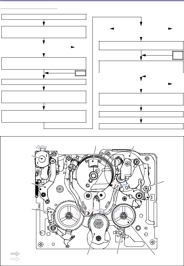
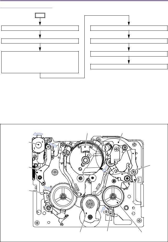
2-3-5 Loading-4 (Blank Search-1)
Blank Search.
Capstan Motor (2) rotates counterclockwise (forward, 3× speed, 0.45 sec), Idler (3) turns
to engage with T Reel Ass'y (4) for taking up tape.
Whether signal is recorded on tape is checked. |
|
|
|
|
|
|
C |
||
|
||||
|
|
|
|
|
|
Yes |
No |
||
|
||||
After Capstan Motor (2) accelerates forward to 5× speed, it continues to rotate (0.56 sec), and T Reel Ass'y (4) takes up tape.
C
Capstan Motor (2) stops.
Capstan Motor (2) rotates clockwise (reversely, 3× speed, 0.45 sec), Idler (3) turns
to engage with S Reel Ass'y (12) for taking up tape.
After Capstan Motor (2) accelerates reversely to 5× speed, it continues to rotate,
and S Reel Ass'y (12) takes up tape.
D2 |
|
|
Status change from without |
|
|
D1 |
|
|
|
||||||
|
|
|
record to with record is checked. |
|
|
|
|
Rush in BOT |
1.8 sec |
||||||
|
|
|
|
Status change |
elapses |
||
|
|
|
|
||||
After status change is detected, Capstan Motor (2) rotates continuously for 0.67 sec and stops.
D1'
D2'
Capstan Motor (2) rotates counterclockwise (forward, 3× speed, 0.76 sec), and
T Reel Ass'y (4) takes up tape.
|
|
|
|
|
|
|
|
|
|
|
|
|
D1" |
|
|
|
|
|
|
|
|||
|
|
|
|
|
|
|
|
|
|
|
|
|
|
|
|
Camera/VCR mode check. |
|
|
E |
|
|||
VCR |
|||||||
|
|
|
|
|
|||
|
Camera |
|
|
||||
|
|
|
|
|
|||
Capstan Motor (2) rotates for 0.78 sec while decelerating from 3× speed to unit speed forward, and T Reel Ass'y (4) takes up tape.
Capstan Motor (2) stops.
Standby at Recpause status.
Drum Unit (1) |
Capstan Motor (2) |
Loading Motor (5)
 Review Arm
Ass'y(11)
Tension Arm |
Pinch Arm |
|
Ass'y(10) |
||
Ass'y(7) |
||
|
Main S Brake (13)
S Reel Ass'y (12) 
LOADING
Idler (3) Main T Brake (14) T Reel Ass'y(4)
UNLOADING
Fig. 1-13
1-13
DMC III
CHAPTER 1. OPERATION
2-3-6 Loading-5 (Blank Search-2)
D1
Capstan Motor (2) stops.
Whether recorded at current tape position is checked. 

 D1'
D1'
Yes |
No |
|
Capstan Motor (2) rotates counterclockwise (forward, 3× speed, 0.45 sec),
and T Reel Ass'y (4) takes up tape.
Capstan Motor (2) accelerates and continues to rotate (forward, 9× speed, 1.9 sec),
and T Reel Ass'y (4) takes up tape.
Capstan Motor (2) stops.
D1"
Drum Unit (1) |
Capstan Motor (2) |
Loading Motor (5)
 Review Arm
Ass'y(11)
Tension Arm |
Pinch Arm |
|
Ass'y(10) |
||
Ass'y(7) |
||
|
Main S Brake (13)
S Reel Ass'y (12) 
Idler (3) |
Main T Brake (14) |
T Reel Ass'y(4) |
Fig. 1-14
1-14
DMC III CHAPTER 1. OPERATION
2-3-7 Loading-6 (Blank Search-3)
D2
Capstan Motor (2) stops.
Capstan Motor (2) rotates counterclockwise (forward, 3× speed), and T Reel Ass'y (4) takes up tape until tape leader is concealed.
After tape leader is concealed, Capstan Motor (2) continues to rotate for specified time and then stops.
Loading Motor (5) rotates clockwise.
Pinch Arm Ass'y (10) releases Capstan Shaft. Main S Brake (13) is engaged with S Reel Ass'y (12) to prevent it from turning.
Tension Arm Ass'y (7) turns clockwise. Main T Brake (14) is engaged with T Reel Ass'y (4)
to prevent it from turning.
STOP Position is detected.
Loading Motor (5) stops rotating.
Loading Motor (5) rotates counterclockwise.
Pinch Arm Ass'y (10) is pressed against Capstan Shaft.
Main S Brake (13) releases S Reel Ass'y (12) to make it free to turn.
Main T Brake (14) releases T Reel Ass'y (4) to make it free to turn.
PLAY Position is detected.
Loading Motor (5) stops rotating.
D2'
Drum Unit (1) |
Capstan Motor (2) |
Loading Motor (5)
 Review Arm
|
Ass'y (11) |
|
Tension Arm |
Pinch Arm |
|
Ass'y (10) |
||
Ass'y (7) |
||
|
Main S Brake (13)
S Reel Ass'y (12) 
Idler (3) |
Main T Brake (14) |
T Reel Ass'y(4) |
Fig. 1-15
1-15
DMC III CHAPTER 1. OPERATION
2-3-8 Loading-7 (Blank Search-4)
E
Capstan Motor (2) stops.
Loading Motor (5) rotates counterclockwise.
Pinch Arm Ass'y (10) releases Capstan Shaft. Main S Brake (13) is engaged with S Reel Ass'y (12) to prevent it from turning.
Tension Arm Ass'y (7) turns clockwise. Main T Brake (14) is engaged with T Reel Ass'y (4)
to prevent it from turning.
STOP Position is detected.
Loading Motor (5) stops rotating.
Drum Unit (1) stops.
Standby at STOP status.
Drum Unit (1) |
Capstan Motor (2) |
Loading Motor (5)
 Review Arm
Ass'y (11)
Tension Arm |
Pinch Arm |
|
Ass'y (10) |
||
Ass'y (7) |
||
|
Main S Brake (13)
S Reel Ass'y (12) 
Idler (3) |
Main T Brake (14) |
T Reel Ass'y(4) |
Fig. 1-16
1-16
 Loading...