


 Loading...
Video Display
Instruction Manual
• Before use, be sure to read this guide, including the
safety and handling precautions. |
|
• Reading this guide will help you learn to use the video |
|
display properly. |
|
• Store this guide safely so that you can use it in the future. |
English |

Table of Content |
|
Introduction................................................................................................................................... |
4 |
About this manual..................................................................................................................................... |
4 |
Trademarks............................................................................................................................................... |
4 |
Supplied Accessories................................................................................................................................ |
4 |
Important Usage Instructions....................................................................................................... |
5 |
Safety Instructions and Handling Precautions.............................................................................. |
6 |
Features...................................................................................................................................... |
11 |
Nomenclature.............................................................................................................................. |
12 |
Installation/Connection............................................................................................................... |
15 |
How to Carry the Main Unit..................................................................................................................... |
15 |
Procedures to attach the protection panel............................................................................................... |
15 |
Procedures to attach/detach stands....................................................................................................... |
16 |
Preventing from Tipping.......................................................................................................................... |
17 |
Mounting the Main Unit on a Stand or Wall............................................................................................. |
18 |
Connecting the Main Unit to Input Devices.............................................................................................. |
19 |
Turning on the Power.................................................................................................................. |
21 |
Turning on the Power of the Main Unit.................................................................................................... |
21 |
Installing the AC power cord clamp HC-01 (Included)............................................................................. |
21 |
Operating the Video Display....................................................................................................... |
22 |
Operating the jog dial.............................................................................................................................. |
22 |
Basic operations to use the OSD menu.................................................................................................. |
22 |
Adjusting Image Quality While Viewing the Entire Image.......................................................................... |
24 |
Temporarily Saving Parameters (Anchor Point Setting)............................................................................ |
25 |
Enlarging the display (Zoom function)...................................................................................................... |
25 |
Changing Image Quality Automatically According to Input Signal............................................................ |
26 |
Adjust image quality on left/right side of screen (image comparison mode)............................................. |
27 |
Calibration without a PC......................................................................................................................... |
27 |
Export/Import.......................................................................................................................................... |
29 |
Set Date/Time......................................................................................................................................... |
31 |
Inputting Characters............................................................................................................................... |
32 |
Using the Function (F) Buttons................................................................................................................ |
32 |
Using the Channel (CH) Button............................................................................................................... |
33 |
Checking Signal Information and Status of the Main Unit........................................................................ |
34 |
Operating the video display using an external device [LAN terminal]........................................................ |
35 |
Operating the video display using an external device [USB terminal: Wi-Fi connection]........................... |
36 |
Use a web browser to remotely operate the video display....................................................................... |
37 |
OSD Menu.................................................................................................................................. |
39 |
OSD Menu Index.................................................................................................................................... |
39 |
2 Table of Content

Adjustment............................................................................................................................................. |
46 |
Channel Settings..................................................................................................................................... |
60 |
Display Settings...................................................................................................................................... |
66 |
Audio Settings........................................................................................................................................ |
69 |
Marker Settings....................................................................................................................................... |
70 |
Function Settings.................................................................................................................................... |
75 |
Picture Function Settings........................................................................................................................ |
85 |
System Settings...................................................................................................................................... |
89 |
Signal Information................................................................................................................................... |
96 |
System Information................................................................................................................................. |
96 |
Main specifications/Performance............................................................................................... |
97 |
Dimensions............................................................................................................................................. |
99 |
Appendix................................................................................................................................... |
100 |
Supported Signal Format...................................................................................................................... |
100 |
Image/Frame Display............................................................................................................................ |
115 |
Error Messages......................................................................................................................... |
118 |
Troubleshooting........................................................................................................................ |
120 |
Software Used in This Product................................................................................................. |
122 |
Index......................................................................................................................................... |
126 |
Table of Content |
3 |
Introduction
Thank you for purchasing the Video Display DP-V2420 / DP-V2421.
The On Screen Display (thereafter referred to OSD) default language setting is English. To change the OSD menu language setting, please refer to p. 89.
About this manual
The illustrations used in this document are for the DP-V2420. Some of the illustrations used in the manual have been simplified for clarity.
Conventions used in this manual
 : Indicates a reference page.
 Note: Indicates a note.
 Reference: Indicates reference information.
 CAUTION: Indicates an item you must observe.
Trademarks
•HDMI, HDMI logo, and High-Definition Multimedia Interface are trademarks or registered trademarks of HDMI Licensing LLC in the U.S. and other countries.
•VESA is a registered trademark or trademark of Video Electronics Standards Association in the U.S. and other countries.
•Wi-Fi, WPA, and WPA2 are registered trademarks of the Wi-Fi Alliance.
•Apple and Safari are trademarks of Apple Inc. registered in the United States and other countries.
•Google and Google Chrome are trademarks or registered trademarks of Google LLC.
•Other product and company names herein are trademarks or registered trademarks of their respective owners.
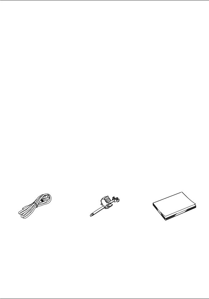
Supplied Accessories
The following items are supplied with this product. Please check before using.
|
|
|
|
|
AC Power Cord HT-21 |
AC Power Cord clamp |
Instruction Manual |
||
|
|
HC-01 |
(this document) |
|
4 Introduction
Important Usage Instructions
For the customers in the U.S.A.
This equipment has been tested and found to comply with the limits for a Class A digital device, pursuant to Part 15 of the FCC Rules.
These limits are designed to provide reasonable protection against harmful interference when the equipment is operated in a commercial environment. This equipment generates, uses, and can radiate radio frequency energy and, if not installed and used in accordance with the instruction manual, may cause harmful interference to radio communications. Operation of this equipment in a residential area is likely to cause harmful interference in which case the user will be required to correct the interference at his own expense.
Do not make any changes or modifications to the equipment unless otherwise specified in the manual. If such changes or modifications should be made, you could be required to stop operation of the equipment.
Use of shielded cable is required to comply with class A limits in Subpart B of Part 15 of FCC Rules.
This device complies with Part 15 of the FCC Rules. Operation is subject to the following two conditions: (1) This device may not cause harmful interference, and (2) this device must accept any interference received, including interference that may cause undesired operation.
Canon U.S.A Inc.
One Canon Park, Melville, NY 11747, U.S.A.
Tel No. (631)330-5000
For the customers in Canada
CAN ICES-3 (A) / NMB-3 (A)
For the customers in Europe
Warning;
This is a class A product. In a domestic environment this product may cause radio interference in which case the user may be required to take adequate measures.
CANON INC.
30-2, Shimomaruko 3-chome, Ohta-ku, Tokyo 146-8501, Japan
CANON EUROPA N.V.
Bovenkerkerweg 59, 1185 XB Amstelveen, The Netherlands
Only for European Union and EEA (Norway, Iceland and Liechtenstein)
This symbol indicates that this product is not to be disposed of with your household waste, according to the WEEE Directive (2012/19/EU) and national legislation. This product should be handed over to a designated collection point, e.g., on an authorized one-for-one basis when you buy a new similar product or to an authorized collection site for recycling waste electrical and electronic equipment (EEE). Improper handling of this type of waste could have a possible negative impact on the environment and human health due to potentially hazardous substances that are generally associated with EEE. At the same time, your cooperation in the correct disposal of this product will contribute to the effective usage of natural resources. For more information about where you can drop off your waste equipment for recycling, please
contact your local city office, waste authority, approved WEEE scheme or your household waste disposal service. For more information regarding return and recycling of WEEE products, please visit
www.canon-europe.com/weee.
Important Usage Instructions |
5 |

Safety Instructions and Handling Precautions
Be sure to read these instructions in order to operate the product safely.
Follow these instructions to prevent injury or harm to the operator of the product or others.
 WARNING
Denotes the risk of serious injury or death.
•Do not disassemble or modify the video display.
Inside, the video display contains high-voltage/extremely hot/movable parts that can cause fire, electric shock, burns or injury.
•Do not insert foreign objects or liquids into the video display.
If metallic objects, flammable objects or liquids get inside the video display, this may cause fire, electric shock or malfunction.
•Be sure to use the correct voltage.
Using a power source with a voltage other than that specified in this instruction manual can cause fire or electric shock. Always use the supplied (or specified) AC power cord. For your safety, do not use this AC power cord to power other equipment.
•Do not use the video display in the following places.
Doing so can cause fire, electric shock or malfunction. -- Next to a window when it is raining or snowing. -- Places subject to high humidity and dusty places.
-- Places exposed to water drops or moisture such as bathrooms or watering places. -- Places directly exposed to soot, smoke or steam, or nearby heaters and humidifiers. -- Places where flammable gases may be present.
-- Places exposed to direct sunlight.
•Do not install or store the video display in places exposed to direct sunlight.
The video display's internal temperature can rise and cause fire or malfunction.
•Do not damage the power cord.
Do not place heavy objects on the power cord and do not pull, modify, heat or tie the power cord in a bundle. The power cord may be damaged (exposed or broken wires, etc.) and cause fire or electric shock.
•When using three-pronged plugs with a ground connection:
Always connect the ground prong.
A short circuit occurring when the ground prong is not connected can cause fire or electric shock. The video display's power cable features a three-pronged plug.
•Do not touch the power cable or plug during lightning storms.
This can cause electric shock.
•Do not touch the power cable or plug with wet hands.
This can cause electric shock.
6 Safety Instructions and Handling Precautions

•Observe the following precautions regarding the power source and power plug.
Failing to do so can cause fire or electric shock.
-- Insert the power plug fully and securely into the power outlet. Do not use a damaged power cable or plug or a
loose power outlet.
-- Hold the plug itself when unplugging the power cable. Pulling the power cord can damage the power cord and cause fire or electric shock.
-- Periodically remove any dust buildup from the power plug.
-- Do not obstruct the access to the power plug by placing other objects around it. -- Do not connect many power cords to the same power outlet.
-- When using an extension cable, make sure the total power consumption of the devices you connect to the extension cable does not exceed its rated power.
•If the video display was dropped or exposed to a strong impact, turn it off immediately and unplug the power plug from the power outlet.
The video display is a precision instrument and continued use in such case can result in a short circuit and cause fire or electric shock.
•Before starting any maintenance work, turn off the video display and unplug the power plug from the power outlet.
Failing to do so can cause electric shock.
•Before moving, installing, removing or connecting the video display to peripheral devices, turn off the video display and all connected devices and unplug their power plugs from the power outlet.
Failing to do so can cause fire, electric shock or malfunction.
•In any case of unusual circumstances such as the presence of smoke or strange sounds or smell, turn off immediately the video display and unplug the power plug from the power outlet.
Continued use can cause fire or electric shock.
•Do not obstruct the access to the power plug so it can always be easily unplugged.
Failing to disconnect the power plug immediately after unusual circumstances have occurred can cause fire or electric shock.
•Do not block the ventilation holes.
Blocking the video display's vent holes can result in the internal temperature rising and cause fire or malfunction. Observe the following precautions to ensure proper ventilation.
-- Do not push the video display into narrow confined spaces or enclosures. -- Do not wrap the video display in cloth or other materials.
-- Do not place the video display facing up, lay it sideways or upside-down.
•For your safety, unplug the power plug from the power outlet when not using the video display for extended
periods of time.
Dust buildup on the power plug can cause fire.
•If the screen is damaged, do not touch the leaking liquid crystal or other internal liquids.
If the LCD panel is damaged and liquid crystal or other internal liquids leak out, do not put the liquids in the mouth, inhale or swallow it or let it come in contact with the skin. If the liquids get in the eye or mouth, wash it immediately with plenty of water. If the liquids come in contact with the skin or clothes, wipe them immediately with alcohol etc. and wash the exposed area with soap. Leaving the liquids untreated can cause injury or damage.
•Keep all packaging material out of the reach of children.
Packaging material tightly wrapped around someone's head can result in strangulation or suffocation.
Safety Instructions and Handling Precautions |
7 |

 CAUTION
Denotes the risk of injury.
•Do not place any objects on the video display and do not climb on it.
The video display can tip or fall and cause injury.
•Do not install the video display on an unstable surface.
Installing the video display on a wobbly or slanted surface can cause the display to tip or fall and cause injury. Thoroughly check also the strength and sturdiness of the surface where the video display will be placed or installed.
•Take precautions to prevent the video display from tipping or falling.
In an earthquake the video display can tip or fall. For your safety, when installing the video display on a TV stand or other furniture, take precautionary measures to secure the video display against tipping or falling ( 17). Taking such measures can be effective in reducing the risk of injury or damage but the effectiveness of the prevention measures cannot be guaranteed in all earthquakes.
•Always follow the specified procedure to install the video display ( 15).
15).
If the installation is not performed correctly, the video display may tilt or fall and cause injury.
•Inspect the condition of the installation about once per year.
An inadequate fitting or mounting can cause the video display to fall and cause injury.
•When using headphones, set the volume at a safe level.
Listening through headphones at a high volume can harm your hearing.
•Do not look at the screen for long periods of time.
Doing so can cause conditions such as eye strain or decreased vision. When looking at the screen for long periods of time, rest periodically. If you feel discomfort after continued usage, stop using the video display immediately and rest. If you continue to feel discomfort, consult a physician.
8 Safety Instructions and Handling Precautions

When Using the Main Unit
•The screen may be damaged if it is left facing strong source of light. Please take precautions when placing it near a window.
•Do not press firmly on the screen, scratch it or place an object on the screen. It can cause non-uniformity or damage to the panel.
•The screen and cabinet may become warm during use. Note this does not constitute a malfunction.
•Depending on the environment where the video display is used, the internal temperature of the display may rise, resulting in becoming hot to touch. Please take care when handling the video display.
•Viewing the display for prolonged periods of time may lead to eye strain or decreased vision. Please ensure to take rest periodically to avoid these symptoms.
•Refer to Recommendation ITU-R BT.1702 "Guidance for the reduction of photosensitive epileptic seizures caused by television" and related guidelines.
About Backlight
The backlight has a limited service life so its brightness may degrade and color may change due to aging.
About Temporary Screen burn-in
If a stationary image is displayed for a prolonged period, screen burn-in may occur where you see remnants of what was displayed. This is a characteristic of LCD and is not a failure. However, this is only temporary and will disappear when playing video.
About the LCD screen
The screen is produced using extremely high-precision manufacturing techniques, with more than 99.99% of the pixels operating to specification. Less than 0.01% of the pixels may occasionally misfire or appear as black, red, blue or green dots. In addition, this tendency may increase through long term use due to characteristic of the LCD panel. These do not constitute a malfunction.
Condensation
If this equipment is brought into a warm room while it is cold or if the room is heated suddenly, condensation may form on the surface or inside the equipment. Note that the equipment may be damaged if it is used under such condition. If condensation has formed on the surface or inside the equipment, do not use the video display as it may get damaged. Turn the power off and wait until the condensation has evaporated before using the video display.
Safety Instructions and Handling Precautions |
9 |

Cleaning
•Before cleaning, be sure to unplug the power plug from the wall outlet.
•The screen has a special surface treatment, avoid touching it directly with your hand. In addition, never affix adhesive objects such as seals.
•Never use alcohol or benzene, thinner, acidic cleaning solution, alkaline cleaning solution, abrasive or chemical wipes because these will damage the screen.
•If the screen is dirty, wipe gently with soft dry cloth such as cleaning cloth or eye glasses cleaning cloth. Wiping the screen too hard may cause unevenness on the screen or damage the LCD panel. The screen may be scratched if wiped too hard with a cleaning cloth with foreign particles attached.
•When the screen is extremely dirty, wipe with soft cloth such as cleaning cloth or eye glasses cleaning cloth moistened with water-diluted neutral detergent.
•Use a blower to remove dust from the surface of the screen.
•Wipe dirt on cabinet with a soft cloth. If the screen is very dirty, use a moistened cloth with water or mild detergent diluted with water. Do not use alcohol, benzene, paint thinner, or pesticides as they may damage the surface finish or erase characters on the cabinet.
Disposing
•Do not dispose together with normal waste. Do not include the video display in waste that will be taken to landfill.
•Observe the rules and regulations of your local authorities when disposing.
10 Safety Instructions and Handling Precautions
Features
Video Display DP-V2420 / DP-V2421 is an HDR reference display capable of supporting various work flows from shooting through to editing in video production for both digital cinema and broadcasting.
Image quality and functions
• Supports 12G/6G-SDI.
•Equipped with a panel with 4096x2160 resolution and backlight system.
•High luminance and high contrast matched to HDR content is achieved.
•Equipped with the HDR display function. (SMPTE ST 2084 and Hybrid Log-Gamma are supported)
•High uniformity is provided by minimizing any variation due to temperature changes and aging.
•Supports wide DCI-P3 color gamut.
•Displays ITU-R BT.2020 color gamut at the optimum level and supports "Constant Luminance".
•Supports ACESproxy.
•Equipped with functions to assist shooting and video checking, including Wave Form Monitor, Vector Scope, Screen Capture, Zoom, and False Color.
•Supports gamma equivalent to CRT standardized by ITU-R BT.1886.
•A color grading controller (Element-Tk made by Tangent Wave Ltd), external sensor, USB memory, or wireless LAN terminal (Wi-Fi adapter) can be connected to the USB port.
•Separately-sold Display Controller CL-01 can be connected to the LAN terminal.
•Supports "Square Division" and "2 Sample Interleave" video signal transport methods.
•Includes a multi-display function (4 or 2 screens)
•HDR and SDR content can be displayed for comparison.
•Equipped with a HDMI input terminal.
Link with digital cinema cameras
•Supports 4K RAW. Establishes 4K RAW workflow on ACES2065-1.
•CINEMA EOS SYSTEM link
•ARRI / Panasonic Camera System link
Rigidity and flexible installation
•High durability achieved by a metal outer covering.
•The side carrying handle on the main unit is convenient for installation and transporting. The handle and adjustable two position stand provides flexible installation and high portability.
Features 11
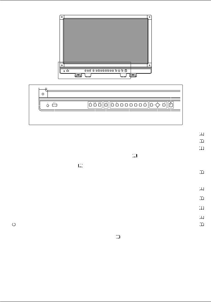
Nomenclature
■■Front face of the main unit
|
1 |
|
|
|
|
|
|
|
|
|
|
|
|
|
|
|
|
|
|
|
|
|
1 |
|
|
|
||||
|
|
|
|
|
|
|
|
|
|
|
|
|
|
|
|
|
|
|
|
|
|
|
|
|||||||
|
|
|
|
|
|
|
|
|
|
|
|
|
|
|
|
|
|
|
|
|
|
|
|
|
||||||
|
2 |
|
|
|
|
|
|
|
|
|
|
|
|
|
|
|
|
|
|
|
|
|
2 |
Aq |
|
|||||
|
|
|
|
|
|
|
|
|
|
|
|
|
|
|
|
|
|
|
|
|
|
|
|
|||||||
|
|
|
|
|
|
|
|
|
|
|
|
|
|
|
|
|
|
|
|
|
|
|
||||||||
|
|
|
|
|
|
|
|
|
|
|
|
|
|
|
|
|
|
|
|
|
|
|
|
|
|
|
|
|
||
|
|
|
|
|
|
|
|
|
|
|
|
|
|
|
|
|
|
|
|
|
|
|
|
|
|
|
|
|
||
|
3 |
|
|
|
|
|
|
|
|
|
|
|
|
|
|
|
|
|
|
|
|
|
|
|
|
|
|
|
|
|
|
|
|
|
|
|
|
|
|
|
|
|
|
|
|
|
|
|
|
|
|
|
|
|
|
|
|
|
|
||
|
|
|
|
|
|
|
|
|
|
|
|
|
|
|
|
|
|
|
|
|
|
|
|
|
|
|
|
|
||
|
|
|
|
|
|
|
|
|
|
|
|
|
|
|
|
|
|
|
|
|
|
|
|
|
|
|
|
|||
|
|
|
|
|
|
|
|
|
|
|
|
|
|
|
|
|
|
|
|
|
|
|
|
|
|
|
|
|
|
|
|
|
|
|
|
4 |
|
|
|
5 |
6 |
|
|
7 |
|
8 |
9 |
|
|||||||||||||
|
|
|
|
|
|
|
|
|
|
|
|
|
|
|
||||||||||||||||
1 |
Front stand |
|
There are two mounting positions. |
|
|
|
|
|
|
|
|
|
16 |
|||||||||||||||||
|
|
|
|
|
|
|
|
|
|
|
|
|
|
|
|
|
|
|
||||||||||||
2 |
Rear stand |
|
This can be detached. |
|
|
|
|
|
|
|
|
|
|
|
|
|
16 |
|||||||||||||
|
|
|
|
|
|
|
|
|
|
|
|
|
|
|
|
|
|
|
||||||||||||
3 |
Headphone terminal |
|
Connection for headphone set. |
|
|
|
|
|
|
|
|
|
|
|
|
|
69 |
|||||||||||||
|
|
|
|
|
|
|
||||||||||||||||||||||||
4 |
USB port |
|
Connection for an external sensor for calibration ( |
27), USB memory, HUB, color |
|
|||||||||||||||||||||||||
|
|
|
|
|
|
grading controller (Element-Tk made by Tangent Wave Ltd), or wireless LAN adapter |
– |
|||||||||||||||||||||||
|
|
|
|
|
|
(Wi-Fi adapter, |
36). |
|
|
|
|
|
|
|
|
|
|
|
|
|
|
|
|
|
||||||
|
|
|
|
|
|
|
|
|
|
|
|
|
|
|
|
|
|
|
|
|
|
|
|
|
||||||
5 |
CH1 to 3 buttons |
|
Changes channel. |
|
|
|
|
|
|
|
|
|
|
|
|
|
|
|
|
|
|
|
33 |
|||||||
|
|
|
|
|
|
|
|
|
|
|
|
|
|
|
||||||||||||||||
6 |
CDL button |
|
Switches between normal and CDL mode. |
|
|
|
|
|
|
|
|
|
– |
|||||||||||||||||
|
|
|
|
|
|
|||||||||||||||||||||||||
7 |
F1 to F8 buttons |
|
Execute the defined function. You can assign different functions on F buttons in the |
32 |
||||||||||||||||||||||||||
|
|
|
|
|
|
normal and CDL modes respectively. |
|
|
|
|
|
|
|
|
|
|||||||||||||||
|
|
|
|
|
|
|
|
|
|
|
|
|
|
|
|
|||||||||||||||
|
|
|
|
|
|
|
|
|||||||||||||||||||||||
8 |
MENU button |
|
Opens/closes the OSD menu, or moves up one level in a menu. |
|
|
22 |
||||||||||||||||||||||||
|
|
|
|
|
|
|||||||||||||||||||||||||
|
Jog dial |
|
Moves the selection frame within the OSD menu, changes the settings (up/down, left/ |
22 |
||||||||||||||||||||||||||
|
|
|
|
|
|
right, rotation) and determines (press) the selection. |
|
|
|
|
|
|||||||||||||||||||
|
|
|
|
|
|
|
|
|
|
|
|
|||||||||||||||||||
|
|
|
|
|
|
|
|
|||||||||||||||||||||||
|
RESET button |
|
Resets the items to be adjusted using the slider and entered characters. |
|
|
22 |
||||||||||||||||||||||||
|
|
|
|
|
|
|
|
|
|
|
|
|
|
|
|
|
|
|
||||||||||||
9 |
|
(Power) button |
|
Turns power On/Off. |
|
|
|
|
|
|
|
|
|
|
|
|
|
21 |
||||||||||||
|
|
|
|
|
|
|
|
|
|
|
|
|
|
|
||||||||||||||||
|
|
|
|
|
|
|
|
|
|
|
|
|
|
|
||||||||||||||||
|
|
|
|
|
|
|||||||||||||||||||||||||
Aq |
Power indicator |
|
Displays the status of the main unit. The brightness of the power indicator can be set |
|
||||||||||||||||||||||||||
|
|
|
|
|
|
from "Off" or "1 (dark) to 5 (brightest)" ( 91). Even when the power indicator is "Off", it |
|
|||||||||||||||||||||||
|
|
|
|
|
|
will flash during firmware update, or when an error is detected. |
|
|
|
|||||||||||||||||||||
|
|
|
|
|
|
Off: when power supply is not connected |
|
|
|
|
|
|
|
|
|
|
||||||||||||||
|
|
|
|
|
|
Green lit: when a power supply is connected and the power of the video display is on |
– |
|||||||||||||||||||||||
|
|
|
|
|
|
Green flash: during calibration or firmware update |
|
|
|
|
|
|
||||||||||||||||||
|
|
|
|
|
|
Amber lit: during standby (a power supply is connected and the power of the video |
|
|||||||||||||||||||||||
|
|
|
|
|
|
|
display is off) |
|
|
|
|
|
|
|
|
|
|
|
|
|
|
|||||||||
|
|
|
|
|
|
Amber flash: when error is detected |
|
|
|
|
|
|
|
|
|
|
||||||||||||||
|
|
|
|
|
|
|
|
|
|
|
|
|
|
|
|
|
|
|
|
|
|
|
|
|
|
|
|
|
|
|
12 Nomenclature
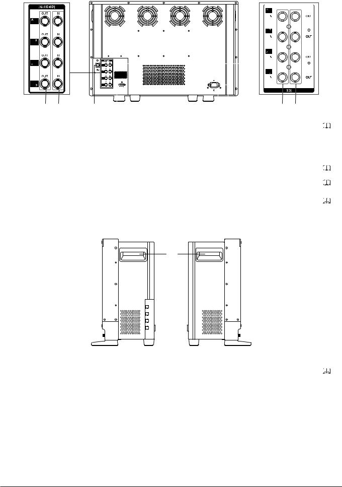
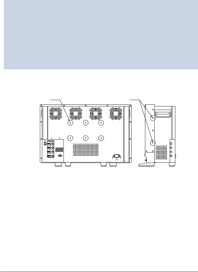
■■ Back face of the main unit
DP-V2420 |
|
|
|
|
|
|
|
|
|
|
|
|
|
|
DP-V2421 |
|
|
|
|
|
|
|
|
|
|
|
|
|
|
|
|
|
|
|
|
|
|
|
|
|
|
|
|
|
|
|
|
|
|
|
|
|
|
|
|
|
|
|
|
|
|
|
|
|
|
|
|
|
|
|
|
|
|
|
|
|
|
|
|
|
|
|
|
|
|
|
|
|
|
|
|
|
|
|
|
|
|
|
|
|
|
|
|
|
|
|
|
|
|
|
|
|
|
|
|
|
|
|
|
|
|
|
|
|
|
|
|
|
|
|
|
|
|
|
|
|
|
|
|
|
|
|
|
|
|
|
|
|
|
|
|
|
|
|
|
|
|
|
|
|
|
|
|
|
|
|
|
|
|
|
|
|
|
|
|
|
|
|
|
|
|
|
|
|
|
|
|
|
|
|
|
|
|
|
|
|
|
|
|
|
|
|
|
|
|
|
|
|
|
|
|
|
|
|
|
|
|
|
|
|
|
|
|
|
|
|
|
|
|
|
|
|
|
|
|
|
|
|
|
|
|
|
|
|
|
|
|
|
|
|
|
|
|
|
|
|
|
|
|
|
|
|
|
|
|
|
|
|
|
|
|
|
|
|
|
|
|
|
|
|
|
|
|
|
|
|
|
|
|
|
|
|
|
|
|
|
|
|
|
|
|
|
|
|
|
|
|
|
|
|
|
|
|
|
|
|
|
|
|
|
|
|
|
|
|
|
|
|
|
|
|
|
|
|
|
|
|
|
|
|
|
|
|
|
|
|
|
|
|
|
|
|
|
|
|
|
|
Ad Af |
sA aA |
Ag hA |
fA dA |
|
|
|
|
|
|
|
Aa |
HDMI input terminal |
Used to input HDMI signals. |
|
|
20 |
|
|
|
|
||
As |
LAN (10/100 BASE) |
Connection for a Display Controller CL-01 (separately sold) or other equipment. |
– |
||
|
terminal |
|
|
|
|
|
|
|
|
|
|
|
|
|
|
|
|
Ad |
SDI output terminal |
Pass through output corresponding to 3G/HD-SDI input terminal. |
|
– |
|
|
|
|
|
|
|
Af |
SDI input terminal |
Used to input SDI signals. |
|
|
19 |
|
|
|
|
|
|
Ag |
Cord clamp mounting |
For installing the AC power cord clamp (Included) |
|
|
21 |
|
hole |
|
|
|
|
|
|
|
|
|
|
|
|
|
|
|
|
Ah |
AC power input |
Connection for the provided AC power supply cord. |
|
21 |
|
|
terminal |
|
|
|
|
|
|
|
|
|
|
|
|
|
|
|
|
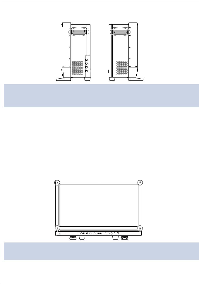
■■Side face of the main unit
jA
|
|
Right side |
Left side |
|
|
|
|
|
|
Aj |
Carrying handle |
Used to install, connect, or carry the unit. |
|
15 |
|
|
|
|
|
Nomenclature 13

 CAUTION
•When connecting an external sensor for calibration to the USB port, the USB cable length must not exceed 3 m (9.8 ft.). Otherwise, communication error may occur and correct calibration may not be possible.
•The video display can perform measurement or calibration of the display using the DP-V Color Adjustment software. Refer to the Canon website for the DP-V Color Adjustment.
• When the video display performs measurement or calibration of the display using the DP-V Color Adjustment or it is being used via LAN, "DP-V2420" will be displayed as the display name.
•Do not use the HUB when connecting a wireless LAN adapter (Wi-Fi adapter) to a USB terminal. The video display may not work.
•For safety, do not connect any connector that may have excessive voltage to the terminal of the video display when connecting peripheral devices.
•Pass through SD-SDI signals are not output correctly.
 Note
Note
•Both FAT16 and FAT32 USB memory devices are supported.
•Proper operation cannot be guaranteed for all USB memories.
•It may take 10 seconds or more for the USB memory to be recognized. If the function to save data on a USB memory is executed during recognition, the message "Detecting USB memory" is displayed.
14 Nomenclature
Installation/Connection
How to Carry the Main Unit
When lifting the video display, please use the carrying handles on the display’s sides.
 CAUTION
•When unpacking, carrying, installing, or connecting the main unit, please note that at least two people are required.
•When carrying the video display, handle it carefully not to touch or damage the screen.
Procedures to attach the protection panel
You can attach the protection panel to protect the screen when carrying the video display or when using it outdoors.
1.Unscrew the four screws on the front face.
Use a 1.5 mm hexagonal key.
Do not lose the removed screws. Do not use these screws for other purposes.
2.Place the protection panel by aligning its corners with the screw holes.
Take care when attaching the panel in order to avoid damaging it.
4×M3
 7 mm deep (Max.)
 CAUTION
• Avoid touching the screen during this step as it may damage it.
Installation/Connection 15

Procedures to attach/detach stands
The main unit comes with two stands which can be detached. The position where the front stand is attached can be changed.
 CAUTION
•Use a flat, clear surface when attaching/detaching the stands.
•The display can tip over if the stand has not been attached.
•Avoid touching the screen during this step as it may damage it.
■■Detaching
1.Place the display with the screen facing down on a soft cloth or cushioning material that is larger than the display.
2.Front stand: Remove the mounting screws (two each) from the left and right stands. Rear stand: Remove the mounting screws (one each) from the left and right stands.
Do not lose the removed screws. Do not use these screws for other purposes.
■■Attaching
1.Place the display with the screen facing down on a soft cloth or cushioning material that is larger than the display.
2.Align the position of the stand and screw hole on the video display.
Alight the convex part of the stand and concave part of the video display.
3.Front stand: Fix the left and right stands using the mounting screws (two each). Rear stand: Fix the left and right stands using the mounting screws (one each).
Rear
Screen side
Concave part
Front stand mounting part (outside)
Concave part
Rear stand 
Convex part
Front stand mounting part (inside)
Convex part
Mounting screw
Front stand
Front stand mounting screw hole
 Note
Note
• It is recommended to mount both front stands in either the outside or inside positions.
16 Installation/Connection
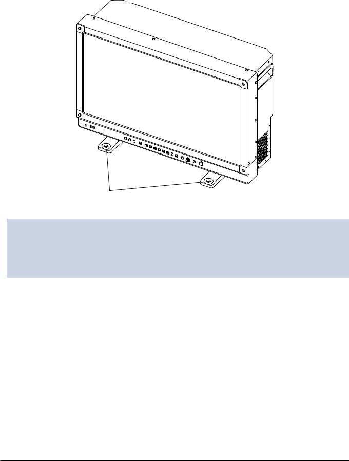
Preventing from Tipping
Fixing the video display using screw holes on the stands can reduce the risk of the main unit tipping over or falling.
1.Use screws that fit the screw holes.
The screw hole size is shown below.
Screw hole 2- 4.5
4.5
 CAUTION
•When securing the main unit to a table or desk, please ensure a table or desk is strong enough to carry the weight of the main unit.
•It is recommended to obtain assistance from another person when performing this step.
•Avoid touching the screen during this step as it may damage it.
Installation/Connection 17
Mounting the Main Unit on a Stand or Wall
This main unit can be fitted to a stand* or to a wall mount bracket*. Remove the stands beforehand ( 16).
16).
* Commercially available.
 CAUTION
•For safety, make sure to perform this step with at least two people.
•When mounting the main unit on a wall, make sure the wall has sufficient strength. If necessary, apply reinforcement. Also, make sure to check the load capacity of the stand or wall mount bracket.
•When the video display is placed on a rack or display stand and ventilation around it is blocked by equipment placed above or below or in a surrounding area, the operating temperature may increase, causing a failure or overheating. In order to maintain the operating temperature condition of the video display (0 ˚C to 40 ˚C), make a space of at least 1U (4.4 cm) above and below and at least 4 cm (1.6 in.) space from its back. Make a sufficient space from peripheral equipment, secure vents, or install a ventilation fan.
•When installing the video display on a wall, make sufficient space from the wall so that cables are not squeezed or twisted.
•Avoid touching the screen during this step as it may damage it.
•Make sure that the main unit does not fall during installation/removal.
1.Attach a commercially available stand or wall mount bracket using the screw holes on the back or side face
of the main unit ( 99).
99).
The screw hole size is shown below.
6×M4 |
|
2×M4 |
|
5 mm deep (Max.) |
Rear |
8 mm deep (Max.) |
Side |
Same on the other side
18 Installation/Connection

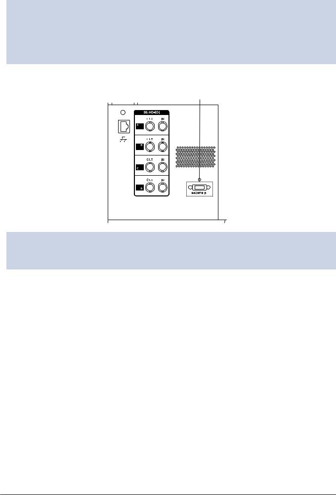
Connecting the Main Unit to Input Devices
The video display has SDI and HDMI input terminals to connect input devices.
 CAUTION
• Check that the power of the video display and input devices is switched off before connecting.
■■SDI input signals
Refer to the SDI input terminals diagram when connecting to the desired input signal. (A, B, C, D)
Display area icon Actual screen display location
A |
B |
A |
B |
C |
D |
||
|
|
C |
D |
DP-V2420 |
|
DP-V2421 |
|
SDI (IN) terminal
|
|
Input signal |
Input terminal |
|
|
Quad Link |
|
Top left, Mapping signal |
Input A |
|
|
(Square Division) |
3G/HD-SDI |
Top right, Mapping signal |
Input B |
|
|
|
|
|
|||
|
12G/6G/3G/HD-SDI |
Bottom left, Mapping signal |
Input C |
|
|
|
|
|
|
||
|
|
Bottom right, Mapping signal |
Input D |
Single input system |
|
Quad Link* |
3G-SDI |
Link 1 |
Input A |
||
|
|||||
(2 Sample Interleave) |
|
Link 2 |
Input B |
|
|
|
|
|
|||
|
|
Link 3 |
Input C |
|
|
|
|
Link 4 |
Input D |
|
|
Dual Link* |
|
Link 1 |
Input A |
|
|
|
3G-SDI |
Link 2 |
Input B |
|
|
|
|
Two input systems |
|||
|
|
Link 1 |
Input C |
||
|
6G/3G-SDI |
|
|||
|
|
|
|
||
|
|
Link 2 |
Input D |
|
|
Single Link |
|
|
Input A/Input B/ |
|
|
|
3G/HD/SD-SDI |
— |
Input C/Input D |
Four input systems |
|
|
|
|
|||
|
12G/6G/3G/HD/SD-SDI |
|
|
||
* The signals are automatically switched when "Image Division" is set to "Automatic".
Installation/Connection 19
 Reference
• The connection is tested using 4VS03A-5C BNC cables (multi) manufactured by Canare Electric Co.
 The connection is tested using D5.5UHDC03E BNC cables manufactured by Canare Electric Co.
•When 3G-SDI RAW signal frequency exceeds 30.00P, it becomes a dual connection.
•Each input terminal is compatible with through output. When signals are input from Input A, connect the cable to the SDI (OUT) terminal of Input A.
■■HDMI input signal
HDMI input terminal
 CAUTION
•Use a HDMI cable with the High Speed logo that complies with the HDMI standard. When a non-compliant HDMI standard cable is used, the video display may not work normally, for example a video becomes choppy or nothing is displayed.
20 Installation/Connection
Turning on the Power
This section describes how to turn on the power of the main unit.
Turning on the Power of the Main Unit
1.Plug the provided AC power cord HT-21 to the AC power supply input terminal at the rear.
The video display goes into standby and the power indicator lights up in amber.
2.Press the power supply button  at the front.
The power indicator lights green.
 Note
Note
•Warming-up is necessary to stabilize the brightness of the video display. Wait at least 10 minutes after turning on the power before using.
Installing the AC power cord clamp HC-01 (Included)
Install the AC power cord clamp before connecting the AC power cord to the main unit.
1.Insert the AC power cord clamp connector into the cord clamp mounting hole (1).
2.Connect the AC power cord to the main unit (2).
3.Secure the AC power cord in place with the holder (3).
4.Press the holder against the main unit (4).
Make sure that there is no slack (A).
•To remove the AC power cord clamp from the AC power cord: Pull the holder lever (5).
•To adjust the length: Push the holder lock lever down (6).
•To remove the AC power cord clamp from the main unit: Press the knobs on the left and right and pull out the clamp (7).
2
3
1
4
A
6 |
5 |
7 |
Turning on the Power |
21 |
Operating the Video Display
Using buttons and jog dial on the video display, you can adjust image quality and configure settings for input signals. In addition, you can assign the frequently used functions to the CH and F buttons.
Operating the jog dial
The procedures to operate the jog dial are described below.
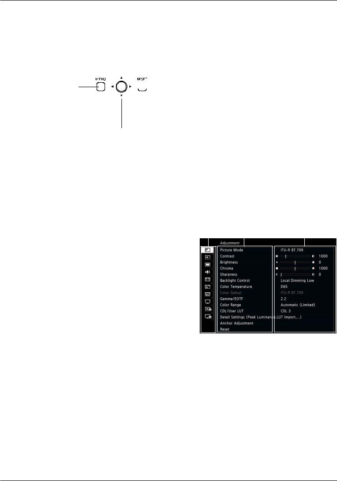
MENU button
Opens/closes the OSD menu, or moves up one level in a menu.

 RESET button
Resets the items to be adjusted using the slider and entered characters.
Jog dial
Up, down, left, right / rotation: Used to move to a different item and change settings.
Press: Confirms settings or moves the selection frame up/down 1 level.
Basic operations to use the OSD menu
Top Screen
This section describes basic operations to use the OSD menu. |
Main Menu |
Sub Menu |
Setting Options |
|||
1. Press the MENU button to open the OSD menu. |
|
|
|
|
|
|
|
|
|
|
|
|
|
|
|
|
|
|
|
|
22 Operating the Video Display

2.Select an item using the jog dial and press it to determine the selection.
The selection frame moves to sub menu.
3.Select an item using the jog dial and press it to determine the selection.
The selection frame moves to setting options.
4.Select the setting using the jog dial.
Settings change according to the operation of the jog dial.
5.Press the jog dial to determine the selection.
The selection frame returns to sub menu.
6.Exit menu.
When you press the MENU button, the selection frame moves up one menu level. Move the selection frame all the way to the main menu on the top screen and then press the MENU button to exit the menu.
 Note
Note
•The following functions can be returned to their factory default settings or their anchor point ( 25) by pressing the RESET button, after adjusting the image quality.
-- "Contrast", "Brightness", "Chroma", "Sharpness", "Power", "Saturation", "Offset", "Slope"
In "User 1-7" mode where you are performing calibration, the setting returns to the value after calibration instead of the factory default.
•To adjust image quality, warming-up is necessary to stabilize the brightness of the video display. Wait at least 10 minutes after turning on the power before using.
•The OSD menu and slider will disappear automatically if no operation is performed for approximately 1 minute. The F button will disappear automatically if no operation is performed for approximately 10 seconds.
•The settings that cannot be set, are grayed out.
Operating the Video Display |
23 |
Adjusting Image Quality While Viewing the Entire Image
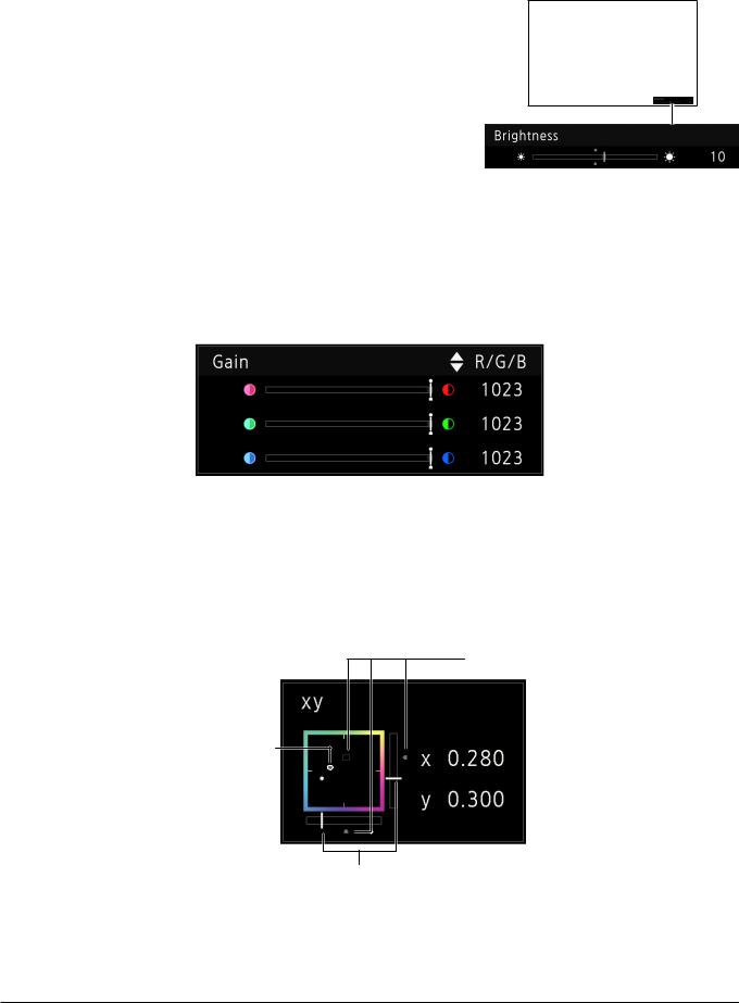
You can adjust the OSD menu to display as a slider at the bottom of the screen. This allows for the image quality to be adjusted whilst it is displayed on the screen.
1.Press the jog dial when the selection frame is on setting options.
A slider appears at the bottom of the screen.
2.Make adjustments using the jog dial with using the slider as guide.
3.When adjustments are completed, press the jog dial.
The screen returns to the original OSD menu.
■■Adjusting "Gain R/G/B, Bias R/G/B" under "Color Temperature"
You can adjust RGB all at once or individually when the slider for adjusting "Gain R/G/B" and "Bias R/G/B" are displayed.
1.Switch the guide in the upper right area of the slider screen using the jog dial ( ).
).
The indication changes to "RGB", "R", "G", and "B".
2.When adjustments are completed, press the jog dial.
The screen returns to the original OSD menu.
■■Adjusting "x, y" under "Color Temperature"
You can adjust "x, y" in "Color Temperature" on the color map.
1.Adjust "x" with the 
 and "y" with
  .
.
The adjusted value is indicated by the " " mark on the color map.
2.When adjustments are completed, press the jog dial.
The screen returns to the original OSD menu.
Default value
Last used value
Current value 

Current value
24 Operating the Video Display
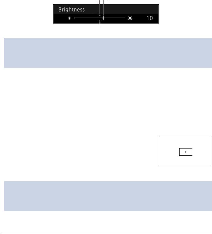
Temporarily Saving Parameters (Anchor Point Setting)
You can temporarily save parameters for "Contrast", "Brightness", "Chroma", "Sharpness", and "HDR Range" and recover the values. See  53 for setting anchor points during CDL adjustment.
1.Press the MENU button to open the OSD menu.
2.Select "Adjustment" using the jog dial and press the dial to determine the selection.
The selection frame moves to sub menu.
3.Select "Anchor Adjustment" using the jog dial and press the dial to determine the selection.
When the confirmation screen appears, select "OK". The parameter is saved and sets anchor point.
4.Adjust the image quality again and press the RESET button on the video display.
Press the RESET button to return to each saved anchor point.
Last used value |
Current value |
Anchor point
 Note
Note
•Executing "Reset" under "Adjustment" or "Reset All Settings" under "System Settings" resets saved anchor points and the settings return to their factory default values.
•When calibration is performed in "User 1-7" under "Picture Mode", the values are saved as anchor points.
Enlarging the display (Zoom function) ( 67)
67)
The zoom display position can be adjusted, and the zoom magnification (2x, 4x, 8x) can be selected.
1. Press the MENU button to open the OSD menu.
2. Select "Display Settings" → "Zoom" using the jog dial.
3. Select "Zoom Preset" using the jog dial.
Select a preset zoom display.
Zoom 2 [x4]
4.Select "Position" using the jog dial.
The zoom adjustment screen is displayed.
-To move the display position: Move the jog dial (

 or rotation).
-To return to the center: Press the RESET button.
5.When adjustments are completed, press the jog dial.
The screen returns to the original OSD menu.
 Note
Note
•When magnifying the image and the OSD menu is not being displayed, you can set the magnification ratio by pressing the jog dial.
•When magnifying the image with the OSD menu closed, you can set the display position using the jog dial (

 ).
).
Operating the Video Display |
25 |

Changing Image Quality Automatically According to Input Signal
On this video display, you can automatically change the image quality according to video resolution or metadata.
■■Changing "Picture Mode" automatically ( 62)
62)
1.Press the MENU button to open the OSD menu.
2.Select "Channel Settings" → "Select Channel" using the jog dial.
Select the channel.
3.Select the "Channel Settings" → "Picture Mode" → "Type" using the jog dial.
Changing by individual video resolution (4K/2K) 1 Select "4K/2K".
2 Set "Picture Mode".
Changing according to video resolution (4K/2K) or metadata (SDI) 1 Select "Automatic".
2 Set "Picture Mode".
4.Press the jog dial to determine the selection.
The setting is confirmed.
■■Changing the image quality setting according to video metadata (HDMI) ( 56)
56)
1.Press the MENU button to open the OSD menu.
2.Select "Adjustment" → "Picture Mode" using the jog dial.
Select "User 1" to "User 7".
3.Select the "Channel Settings" → "Picture Mode" → "Type" using the jog dial.
Select other than "L/R".
4.Select "Adjustment" → "Detail Settings" → "HDMI Link" → "Automatic Adjustment" using the jog dial.
•Select "On".
•See "HDMI Link" ( 56) for the configurable settings.
5.Press the jog dial to determine the selection.
The setting is confirmed.
 Note
Note
•When automatic changing of image quality according to video resolution (4K/2K) or SDI metadata is set, information showing which resolution (4K/2K, etc.) is selected will be displayed at the top right of the menu screen.
26 Operating the Video Display

Adjust image quality on left/right side of screen (image comparison mode)
You can divide the screen in two and adjust the image quality on the left and right sides of the screen individually.
1.Press the MENU button to open the OSD menu.
2.Select "Channel Settings" → "Picture Mode" → "Type" using the jog dial.
After selecting "L/R", press the jog dial to determine the selection.
3.Select the screen to adjust image quality
•When the OSD menu is open:
-- In the "Adjustment" main menu, press the jog dial’s  button. -- In the "Adjustment" main or sub menu, press the CH1 button.
•When the OSD menu is not being displayed: Move the jog dial (
 ).
).
•Each time the target screen is switched, the set "Picture Mode" is displayed at the top.
4.Adjust the image quality on the selected screen.
 Note
Note
•When in Image Comparison mode, an icon showing which screen (L/R) is selected for image quality adjustment will be displayed at the right top of the "Adjustment" menu screen.
•The functions that cannot be used when the right screen is selected are as follows.
-- Sub Menu items for "Adjustment": "Contrast", "Backlight Control", "Peak Luminance Control", "HDR/SDR View", "Calibration"
•When two screens are displayed, you can adjust the image quality on each screen individually and compare them. -- When two screens are displaying the same image ("Single Input Dual View"  63)
63)
-- When two screens are displaying different images ("Multi View (Dual)"  60)
60)
-- The HDR (High Dynamic Range) and SDR (Standard Dynamic Range) displays can be tested side by side. ("HDR/SDR View"  55)
55)
Calibration without a PC ( 56)
56)
When "User 1-7" under "Picture Mode" is selected, you can perform calibration using an external sensor, without using the computer.
The supported external sensors are Konika Minolta Display Color Analyzers CA-310 and CA-210. Be sure to also read the instruction manual of the CA-310 and CA-210.
The video display can perform measurement or calibration of the display using the DP-V Color Adjustment software. Refer to the Canon website for the DP-V Color Adjustment.
1.Connect the display color analyzer to the USB port of the main unit.
2.Open the OSD menu and select "Adjustment" → "Detail Settings" → "Calibration".
Set each target value.
Operating the Video Display |
27 |
3.Press the jog dial and select "Start".
Please follow the information indicated on the screen.
4.Initialize the sensor.
Set the mode dial of the Universal Measuring Probe to "0-CAL".
Press the jog dial of the video display, select "OK", and execute initialization.
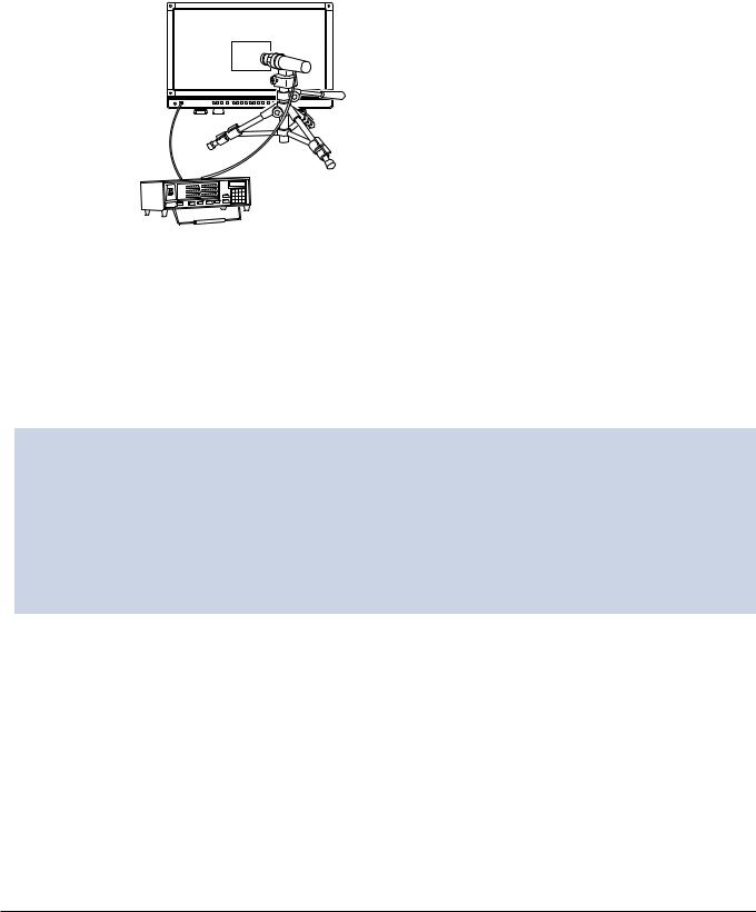
5.Place the universal measuring probe pointing at the center of the video display.
Set the mode dial of the universal measuring probe to "MEAS" and place the probe as shown below according to the displayed content. Press the jog dial of the video display, select "OK", and execute calibration.
Main Unit
Konica Minolta Universal Measuring Probe
CA-310 support: CA-PU32, CA-PU35
CA-210 support: CA-PU12, CA-PU15
Konica Minolta
Display Color Analyzer CA-310, CA-210
6.Finish calibration.
When the message "Calibration is completed." is displayed, press the jog dial and select "OK".
•If the message "Calibration error." is displayed.
Calibration has been terminated due to an error. The main unit returns to the state before calibration. ( 118)
118)
•To cancel calibration
Press the jog dial during calibration and select "Cancel". The main unit returns to the state before calibration.
 Note
Note
•Due to the characteristic of LCD panel and individual difference of CA-310 and CA-210, the calibration results may differ.
•Perform matrix calibration of the display color analyzer prior to calibration. If calibration is performed without performing matrix calibration, an error may occur. Refer to the CA-310 and CA-210 instruction manual for the detail operation.
•Warming-up is necessary to stabilize the brightness of the video display. Wait at least 10 minutes after turning on the power before calibration.
•Perform calibration in a dark room so that no external light enters the sensor. If external light enters the sensor, low brightness characteristics cannot be calibrated correctly.
28 Operating the Video Display
Export/Import
You can export/import LUT and CDL parameters as well as main menu settings. Insert a USB memory stick into the USB port of the main unit.
■■LUT Import ( 54)
54)
1.Press the MENU button to open the OSD menu.
2.Select "Adjustment" → "Detail Settings" → "LUT Import" using the jog dial.
3.Select the file using the jog dial.
In the "Filename" field, search and display a file with extension ".clut" in the root folder.
4.Select the LUT type using the jog dial.
•Select the LUT type by using "User LUT", "Gamma LUT" or "Gamut LUT".
•Refer to the "Concept Drawing of Display Image Processing and LUT". Or, also refer to the "User LUT Creation Guide" on the Canon website.
5.Select "Select LUT" using the jog dial.
Selects User LUT 1-8/Gamma LUT 1-8/Gamut LUT 1-8.
6.Select the standard color gamut using the jog dial.
Select the color gamut used when creating the LUT (when "Gamut LUT" under "LUT Type" is selected).
7.Select "Execute" using the jog dial.
When the confirmation screen appears, select "OK". Import starts.
 Note
Note
•The LUT file is proprietary to Canon Video Display. Refer to the Canon website for the file format and how to create.
•Up to 1000 LUT import files are recognized.
•You can delete the imported LUT. You can specify the name of LUT ( 54).
54).
OSD Menu |
OSD Menu |
OSD Menu |
OSD Menu |
|
CDL Setting |
Gamma/EOTF |
Color |
Base Color |
|
Temperature |
||||
Setting |
Gamut Setting |
|||
|
Setting |
|||
or |
or |
|
|
|
Import LUT file |
Import LUT file |
|
Import LUT file |
|
3D-LUT |
1D-LUT |
|
3D-LUT |
3D-LUT |
|
1D-LUT |
|
|
|
Color |
|
|
|
3D-LUT |
|
Color Gamut |
|
|
User LUT |
|
Gamma LUT |
|
|
|
Temperature |
|
|
|
Gamut LUT |
|
|
|
|
|
|
|
|
|
|
|
|
|
|
|||||
|
|
|
|
|
|
|
|
|
|
|
||||
|
|
|
|
|
|
|
|
|
|
|
|
|
|
|
|
|
|
|
|
|
|
|
|
|
|
|
|
||
|
|
|
|
Gamma 2.2 |
|
|
|
|
|
|
|
|
||
|
|
|
|
|
|
|
|
Color Temperature |
|
|
|
|
||
|
|
|
|
|
|
|
User selectable) |
Color Gamut |
|
|
||||
|
|
|
|
|
|
|
|
|
|
User selectable |
|
|
||
Concept Drawing of Display Image Processing and LUT
Operating the Video Display |
29 |

■■Export/Import Main Menu Settings ( 93)
93)
1.Press the MENU button to open the OSD menu.
2.Select "System Settings" → "Export/Import".
3.Select "Export" or "Import" using the jog dial. Exporting
-Select "Target" from "USB" or "User 1-3".
Export "USB" to the USB memory and "User 1-3" to the built-in memory of the main unit.
-Select "Filename".
Factory default is "dinfo_dpv2420.dat" ( "dinfo_dpv2421.dat"). You can change the name of the file to be exported to the USB memory within 16 one-byte characters including alphabetical characters, numbers, and symbols.
-Select "Execute".
When the confirmation screen appears, select "OK". Export starts.
Importing
-Select "Target" from "USB" or "User 1-3".
Specify the destination to save the file to be imported.
-Select "Filename".
-In "Settings", select "All" or Main Menu name.
-Select "Execute".
When the confirmation screen appears, select "OK". Import starts.
 Note
Note
•After export to "User 1-3", you can select the configurations at startup from "User 1-3" in "Power on Setting" in "System Settings" ( 93).
93).
30 Operating the Video Display
Loading...