


 Loading...
Robert Bosch Power Tools GmbH
70538 Stuttgart
GERMANY
www.bosch-pt.com
1 609 92A 4NJ (2019.04) T / 283
1 609 92A 4NJ
GDB 180 WE + GCR 180
Professional
|
|
|
|
|
|
|
|
|
|
|
|
|
|
|
|
|
|
|
|
|
|
|
|
|
|
|
|
|
|
|
|
|
|
|
|
|
|
|
|
|
|
|
|
|
|
|
de |
Originalbetriebsanleitung |
tr |
Orijinal işletme talimatı |
bg |
Оригинална инструкция |
|||
|
|
|
|
|
en |
Original instructions |
pl |
Instrukcja oryginalna |
mk |
Оригинално упатство за работа |
|||
|
|
|
|
|
fr |
Notice originale |
cs |
Původní návod k používání |
sr |
Originalno uputstvo za rad |
|||
|
|
|
|
|
es |
Manual original |
sk |
Pôvodný návod na použitie |
sl |
Izvirna navodila |
|||
|
|
|
|
|
pt |
Manual original |
hu |
Eredeti használati utasítás |
hr |
Originalne upute za rad |
|||
|
|
|
|
|
it |
Istruzioni originali |
ru |
Оригинальное руководство по |
et |
Algupärane kasutusjuhend |
|||
|
|
|
|
|
nl |
Oorspronkelijke gebruiksaanwijzing |
|
эксплуатации |
lv |
Instrukcijas oriģinālvalodā |
|||
|
|
|
|
|
da |
Original brugsanvisning |
uk |
Оригінальна інструкція з |
lt |
Originali instrukcija |
|||
|
|
|
|
|
sv |
Bruksanvisning i original |
|
експлуатації |
ko |
|
|||
|
|
|
|
|
no |
Original driftsinstruks |
kk |
Пайдалану нұсқаулығының |
ar |
يلصلأا ليغشتلا ليلد |
|||
|
|
|
|
|
fi |
Alkuperäiset ohjeet |
|
түпнұсқасы |
fa |
یلصا یامنهار هچرتفد |
|||
|
|
|
|
|
el |
Πρωτότυπο οδηγιών χρήσης |
ro |
Instrucțiuni originale |
|
|
|
|
|
|
|
|
|
|
|
|
|
|
|
|
|
|
|
|
|
|
|
|
|
|
|
|
|
|
|
|
|
|
|
|
|
|
|
|
|
|
|
|
|
|
|
|
|
|
|
|
|
|
|
|
|
|
|
|
|
|
|
|
|
|
|
|
|
|
|
|
|
|
|

2 |
Deutsch .................................................. |
Seite |
6 |
English ................................................... |
Page |
14 |
Français .................................................. |
Page |
23 |
Español ................................................ |
Página |
32 |
Português .............................................. |
Página |
41 |
Italiano ................................................. |
Pagina |
49 |
Nederlands ............................................. |
Pagina |
58 |
Dansk .................................................... |
Side |
67 |
Svensk .................................................. |
Sidan |
74 |
Norsk..................................................... |
Side |
82 |
Suomi ..................................................... |
Sivu |
89 |
Ελληνικά................................................ |
Σελίδα |
97 |
Türkçe................................................... |
Sayfa 106 |
|
Polski .................................................. |
Strona 114 |
|
Čeština ................................................ |
Stránka 124 |
|
Slovenčina ............................................ |
Stránka 131 |
|
Magyar ................................................... |
Oldal 140 |
|
Русский ............................................. |
Страница 148 |
|
Українська ........................................... |
Сторінка 158 |
|
Қазақ ..................................................... |
Бет 167 |
|
Română ................................................ |
Pagina 177 |
|
Български .......................................... |
Страница 185 |
|
Македонски......................................... |
Страница 194 |
|
Srpski .................................................. |
Strana 203 |
|
Slovenščina .............................................. |
Stran 211 |
|
Hrvatski ............................................... |
Stranica 219 |
|
Eesti.................................................. |
Lehekülg 227 |
|
Latviešu .............................................. |
Lappuse 235 |
|
Lietuvių k. ............................................. |
Puslapis 244 |
|
............................................... |
252 |
|
يبرع.................................................. |
ةحفصلا 261 |
|
یسراف .................................................. |
هحفص 271 |
|
.......................................................... |
|
I |
1 609 92A 4NJ | (03.04.2019) |
|
|
|
Bosch Power Tools |
|
|
|
|
|
|
|
|
|
|
|
|
|
|
|
|
|
|
|
| 3
(1)
(16)
(2)
(3)
(15)
(14)
(13)
(11)
(4)
(12)
 (5)
(5)
(6)
(10)
(7)
(8) |
(9) |
GDB 180 WE
Bosch Power Tools |
|
|
|
1 609 92A 4NJ | (03.04.2019) |
|
|
|
|
|
|
|
|
|
|
|
|
|
|
|
|
|
|
|

4 |
(17) |
|
|
(29) |
|
(28) |
|
(17) |
(18) |
(27) |
|
|
(19) |
(26) |
|
(22) |
(20) |
|
(21) |
|
|
(22) |
(22) |
|
(23) |
|
|
(22) (25) |
(24)
GCR 180
1 609 92A 4NJ | (03.04.2019) |
|
|
|
Bosch Power Tools |
|
|
|
|
|
|
|
|
|
|
|
|
|
|
|
|
|
|
|

| 5
A B
(3) 


(4) 


(17)
(30)
|
|
(31) |
|
(18) |
(19) |
|
(32) |
|
|||
|
|
||
|
|
|
|
C |
|
|
D |
|
(20) |
|
|
|
|
|
|
|
|
|
|
|
|
|
|
|
|
|
|
|
(34) |
|
(35) |
|
(36) |
|
(25) |
|
(33) |
|
(23) |
Bosch Power Tools |
1 609 92A 4NJ | (03.04.2019) |

6 | Deutsch
Deutsch
Sicherheitshinweise
Allgemeine Sicherheitshinweise für
Elektrowerkzeuge
 WARNUNG Lesen Sie alle Sicherheitshinweise, Anweisungen, Bebilderungen
und technischen Daten, mit denen dieses Elektrowerk-
zeug versehen ist. Versäumnisse bei der Einhaltung der Si-
cherheitshinweise und nachfolgenden Anweisungen können
elektrischen Schlag, Brand und/oder schwere Verletzungen
verursachen.
Bewahren Sie alle Sicherheitshinweise und Anweisungen
für die Zukunft auf.
Der in den Sicherheitshinweisen verwendete Begriff „Elektrowerkzeug“ bezieht sich auf netzbetriebene Elektrowerkzeuge (mit Netzleitung) und auf akkubetriebene Elektrowerkzeuge (ohne Netzleitung).
ACHTUNG! Beim Gebrauch von Elektrowerkzeugen sind zum Schutz gegen elektrischen Schlag, Verletzungsund Brandgefahr folgende grundsätzliche Sicherheitsmaßnahmen zu beachten. Lesen Sie alle diese Hinweise, bevor Sie dieses Elektrowerkzeug benutzen, und bewahren Sie die Sicherheitshinweise gut auf.
Arbeitsplatzsicherheit
uHalten Sie Ihren Arbeitsbereich sauber und gut beleuchtet. Unordnung oder unbeleuchtete Arbeitsbereiche können zu Unfällen führen.
uArbeiten Sie mit dem Elektrowerkzeug nicht in explosionsgefährdeter Umgebung, in der sich brennbare Flüssigkeiten, Gase oder Stäube befinden. Elektrowerkzeuge erzeugen Funken, die den Staub oder die Dämpfe entzünden können.
uHalten Sie Kinder und andere Personen während der Benutzung des Elektrowerkzeugs fern. Bei Ablenkung können Sie die Kontrolle über das Elektrowerkzeug verlieren.
Elektrische Sicherheit
uDer Anschlussstecker des Elektrowerkzeuges muss in die Steckdose passen. Der Stecker darf in keiner Weise verändert werden. Verwenden Sie keine Adapterstecker gemeinsam mit schutzgeerdeten Elektrowerkzeugen. Unveränderte Stecker und passende Steckdosen verringern das Risiko eines elektrischen Schlages.
uVermeiden Sie Körperkontakt mit geerdeten Oberflächen wie von Rohren, Heizungen, Herden und Kühlschränken. Es besteht ein erhöhtes Risiko durch elektrischen Schlag, wenn Ihr Körper geerdet ist.
uHalten Sie Elektrowerkzeuge von Regen oder Nässe fern. Das Eindringen von Wasser in ein Elektrowerkzeug erhöht das Risiko eines elektrischen Schlages.
uZweckentfremden Sie die Anschlussleitung nicht, um das Elektrowerkzeug zu tragen, aufzuhängen oder um den Stecker aus der Steckdose zu ziehen. Halten Sie die Anschlussleitung fern von Hitze, Öl, scharfen Kanten oder sich bewegenden Teilen. Beschädigte oder verwickelte Anschlussleitungen erhöhen das Risiko eines elektrischen Schlages.
uWenn Sie mit einem Elektrowerkzeug im Freien arbeiten, verwenden Sie nur Verlängerungskabel, die auch für den Außenbereich geeignet sind. Die Anwendung einer für den Außenbereich geeigneten Verlängerungsleitung verringert das Risiko eines elektrischen Schlages.
uWenn der Betrieb des Elektrowerkzeuges in feuchter Umgebung nicht vermeidbar ist, verwenden Sie einen Fehlerstromschutzschalter. Der Einsatz eines Fehlerstromschutzschalters vermindert das Risiko eines elektrischen Schlages.
Sicherheit von Personen
uSeien Sie aufmerksam, achten Sie darauf, was Sie tun, und gehen Sie mit Vernunft an die Arbeit mit einem Elektrowerkzeug. Benutzen Sie kein Elektrowerkzeug, wenn Sie müde sind oder unter dem Einfluss von Drogen, Alkohol oder Medikamenten stehen. Ein Moment der Unachtsamkeit beim Gebrauch des Elektrowerkzeuges kann zu ernsthaften Verletzungen führen.
uTragen Sie persönliche Schutzausrüstung und immer eine Schutzbrille. Das Tragen persönlicher Schutzausrüstung, wie Staubmaske, rutschfeste Sicherheitsschuhe, Schutzhelm oder Gehörschutz, je nach Art und Einsatz des Elektrowerkzeuges, verringert das Risiko von Verletzungen.
uVermeiden Sie eine unbeabsichtigte Inbetriebnahme. Vergewissern Sie sich, dass das Elektrowerkzeug ausgeschaltet ist, bevor Sie es an die Stromversorgung und/oder den Akku anschließen, es aufnehmen oder tragen. Wenn Sie beim Tragen des Elektrowerkzeuges den Finger am Schalter haben oder das Gerät eingeschaltet an die Stromversorgung anschließen, kann dies zu Unfällen führen.
uEntfernen Sie Einstellwerkzeuge oder Schraubenschlüssel, bevor Sie das Elektrowerkzeug einschalten.
Ein Werkzeug oder Schlüssel, der sich in einem drehenden Geräteteil befindet, kann zu Verletzungen führen.
uVermeiden Sie eine abnormale Körperhaltung. Sorgen Sie für einen sicheren Stand und halten Sie jederzeit das Gleichgewicht. Dadurch können Sie das Elektrowerkzeug in unerwarteten Situationen besser kontrollieren.
uTragen Sie geeignete Kleidung. Tragen Sie keine weite Kleidung oder Schmuck. Halten Sie Haare und Kleidung fern von sich bewegenden Teilen. Lockere Kleidung, Schmuck oder lange Haare können von sich bewegenden Teilen erfasst werden.
1 609 92A 4NJ | (03.04.2019) |
|
|
|
Bosch Power Tools |
|
|
|
|
|
|
|
|
|
|
|
|
|
|
|
|
|
|
|

uWenn Staubabsaugund -auffangeinrichtungen montiert werden können, sind diese anzuschließen und richtig zu verwenden. Verwendung einer Staubabsaugung kann Gefährdungen durch Staub verringern.
uWiegen Sie sich nicht in falscher Sicherheit und setzen Sie sich nicht über die Sicherheitsregeln für Elektrowerkzeuge hinweg, auch wenn Sie nach vielfachem Gebrauch mit dem Elektrowerkzeug vertraut sind.
Achtloses Handeln kann binnen Sekundenbruchteilen zu schweren Verletzungen führen.
Verwendung und Behandlung des Elektrowerkzeugs
uÜberlasten Sie das Elektrowerkzeug nicht. Verwenden Sie für Ihre Arbeit das dafür bestimmte Elektrowerkzeug. Mit dem passenden Elektrowerkzeug arbeiten Sie besser und sicherer im angegebenen Leistungsbereich.
uBenutzen Sie kein Elektrowerkzeug, dessen Schalter defekt ist. Ein Elektrowerkzeug, das sich nicht mehr einoder ausschalten lässt, ist gefährlich und muss repariert werden.
uZiehen Sie den Stecker aus der Steckdose und/oder entfernen Sie einen abnehmbaren Akku, bevor Sie Geräteeinstellungen vornehmen, Einsatzwerkzeugteile wechseln oder das Elektrowerkzeug weglegen. Diese Vorsichtsmaßnahme verhindert den unbeabsichtigten Start des Elektrowerkzeuges.
uBewahren Sie unbenutzte Elektrowerkzeuge außerhalb der Reichweite von Kindern auf. Lassen Sie keine Personen das Elektrowerkzeug benutzen, die mit diesem nicht vertraut sind oder diese Anweisungen nicht gelesen haben. Elektrowerkzeuge sind gefährlich, wenn sie von unerfahrenen Personen benutzt werden.
uPflegen Sie Elektrowerkzeuge und Einsatzwerkzeug mit Sorgfalt. Kontrollieren Sie, ob bewegliche Teile einwandfrei funktionieren und nicht klemmen, ob Teile gebrochen oder so beschädigt sind, dass die Funktion des Elektrowerkzeuges beeinträchtigt ist. Lassen Sie beschädigte Teile vor dem Einsatz des Gerätes reparieren. Viele Unfälle haben ihre Ursache in schlecht gewarteten Elektrowerkzeugen.
uHalten Sie Schneidwerkzeuge scharf und sauber.
Sorgfältig gepflegte Schneidwerkzeuge mit scharfen Schneidkanten verklemmen sich weniger und sind leichter zu führen.
uVerwenden Sie Elektrowerkzeug, Zubehör, Einsatzwerkzeuge usw. entsprechend diesen Anweisungen. Berücksichtigen Sie dabei die Arbeitsbedingungen und die auszuführende Tätigkeit. Der Gebrauch von Elektrowerkzeugen für andere als die vorgesehenen Anwendungen kann zu gefährlichen Situationen führen.
uHalten Sie Griffe und Griffflächen trocken, sauber und frei von Öl und Fett. Rutschige Griffe und Griffflächen erlauben keine sichere Bedienung und Kontrolle des Elektrowerkzeugs in unvorhergesehenen Situationen.
Service
uLassen Sie Ihr Elektrowerkzeug nur von qualifiziertem Fachpersonal und nur mit Original-Ersatzteilen repa-
Deutsch | 7
rieren. Damit wird sichergestellt, dass die Sicherheit des Elektrowerkzeuges erhalten bleibt.
Sicherheitshinweise für Diamantbohrmaschinen
uLeiten Sie bei der Ausführung von Bohrarbeiten, die den Einsatz von Wasser erfordern, das Wasser weg vom Arbeitsbereich oder verwenden Sie einen Flüs- sigkeits-Auffangring. Derartige Vorsichtsmaßnahmen halten den Arbeitsbereich trocken und verringern das Risiko eines elektrischen Schlages.
uBetreiben Sie das Elektrowerkzeug an den isolierten Griffflächen, wenn Sie Arbeiten ausführen, bei denen das Schneidwerkzeug verborgene Stromleitungen oder die eigene Anschlussleitung treffen kann. Der Kontakt eines Schneidwerkzeugs mit einer spannungsführenden Leitung kann auch metallene Teile des Elektrowerkzeugs unter Spannung setzen und zu einem elektrischen Schlag führen.
uTragen Sie beim Diamantbohren einen Gehörschutz.
Die Einwirkung von Lärm kann Gehörverlust bewirken.
uWenn das Einsatzwerkzeug klemmt, üben Sie keinen Vorschub mehr aus und schalten Sie das Werkzeug aus. Überprüfen Sie den Grund des Verklemmens und beseitigen Sie die Ursache für klemmende Einsatzwerkzeuge.
uWenn Sie eine Diamantbohrmaschine, die im Werkstück steckt, wieder starten wollen, prüfen Sie vor dem Einschalten, ob sich das Einsatzwerkzeug frei dreht. Wenn das Einsatzwerkzeug klemmt, dreht es sich möglicherweise nicht, kann zur Überlastung des Werkzeugs führen oder dazu, dass sich die Diamantbohrmaschine vom Werkstück löst.
uBei Befestigung des Bohrständers am Werkstück mittels Dübel und Schrauben stellen Sie sicher, dass die verwendete Verankerung in der Lage ist, die Maschine während des Gebrauchs sicher zu halten. Wenn das Werkstück nicht widerstandsfähig oder porös ist, kann der Dübel herausgezogen werden, wodurch sich der Bohrständer vom Werkstück löst.
uBei Befestigung des Bohrständers am Werkstück mittels Vakuumplatte achten Sie darauf, dass die Oberfläche glatt, sauber und nicht porös ist. Befestigen Sie den Bohrständer nicht an laminierten Oberflächen, wie z.B. auf Fliesen und Beschichtungen von Verbundwerkstoffen. Wenn die Oberfläche des Werkstücks nicht glatt, plan oder ausreichend befestigt ist, kann sich die Vakuumplatte vom Werkstück lösen.
uStellen Sie vorm und beim Bohren sicher, dass der Unterdruck ausreichend ist. Ist der Unterdruck nicht ausreichend, kann sich die Vakuumplatte vom Werkstück lösen.
uFühren Sie niemals Bohrungen durch, außer nach unten, wenn die Maschine nur mittels Vakuumplatte befestigt ist. Bei Verlust des Vakuums löst sich die Vakuumplatte vom Werkstück.
uSorgen Sie beim Bohren durch Wände oder Decken dafür, dass Personen und Arbeitsbereich auf der an-
Bosch Power Tools |
|
|
|
1 609 92A 4NJ | (03.04.2019) |
|
|
|
|
|
|
|
|
|
|
|
|
|
|
|
|
|
|
|
8 | Deutsch
deren Seite geschützt sind. Die Bohrkrone kann über
das Bohrloch hinausgehen und der Bohrkern kann auf der
anderen Seite herausfallen.
uVerwenden Sie dieses Werkzeug nicht für Überkopfbohrarbeiten mit Wasserzuführung. Das Eindringen von Wasser in das Elektrowerkzeug erhöht das Risiko eines elektrischen Schlages.
uVerwenden Sie geeignete Suchgeräte, um verborgene Versorgungsleitungen aufzuspüren, oder ziehen Sie die örtliche Versorgungsgesellschaft hinzu. Kontakt mit Elektroleitungen kann zu Feuer und elektrischem Schlag führen. Beschädigung einer Gasleitung kann zur Explosion führen. Eindringen in eine Wasserleitung verursacht Sachbeschädigung oder kann einen elektrischen Schlag verursachen.
uTragen Sie rutschfeste Schuhe. Dadurch vermeiden Sie Verletzungen, die durch Ausrutschen auf glatten Flächen entstehen können.
uBetreiben Sie das Elektrowerkzeug niemals ohne den mitgelieferten Fehlerstromschutzschalter (PRCD).
uAchten Sie darauf, dass weder Personen im Arbeitsbereich noch das Elektrowerkzeug mit dem austretenden Wasser in Kontakt kommen.
uVerlassen Sie das Werkzeug nie, bevor es vollständig zum Stillstand gekommen ist. Nachlaufende Einsatzwerkzeuge können Verletzungen verursachen.
uBauen Sie vor der Montage der Bohrmaschine den Bohrständer richtig auf. Richtiger Zusammenbau ist wichtig, um die einwandfreie Funktion zu gewährleisten.
uBefestigen Sie die Bohrmaschine sicher am Bohrständer, bevor Sie sie benutzen. Ein Verrutschen der Bohrmaschine im Bohrständer kann zum Verlust der Kontrolle führen.
uBefestigen Sie den Bohrständer auf einer festen, ebenen Fläche. Wenn der Bohrständer verrutschen oder wackeln kann, kann die Bohrmaschine nicht gleichmäßig und sicher geführt werden.
uHalten Sie das Anschlusskabel der Bohrmaschine fern vom Arbeitsbereich. Beschädigte oder verwickelte Kabel erhöhen das Risiko eines elektrischen Schlages.
uÜberlasten Sie den Bohrständer nicht und verwenden Sie ihn nicht als Leiter oder Gerüst. Überlastung oder Stehen auf dem Bohrständer kann dazu führen, dass sich der Schwerpunkt des Bohrständers nach oben verlagert und er umkippt.
uBewahren Sie unbenutzte Bohrständer außerhalb der Reichweite von Kindern auf. Lassen Sie Personen das Gerät nicht benutzen, die mit diesem nicht vertraut sind oder diese Anweisungen nicht gelesen haben. Geräte sind gefährlich, wenn sie von unerfahrenen Personen benutzt werden.
uSichern Sie vor allen Arbeiten an Bohrständer oder Bohrmaschine, in Arbeitspausen sowie bei Nichtgebrauch den Bohrständer durch Festdrehen der Feststellbremse gegen unbeabsichtigtes Bewegen.
uDas Elektrowerkzeug darf nur an Stromnetzen mit Schutzleiter und ausreichender Dimensionierung betrieben werden.
uBefestigen Sie den Bohrständer beim Betrieb stets mittels Dübel oder Vakuum (Zubehör), um unbeabsichtigtes Umkippen des Bohrständers bei eingesetzter Diamantbohrmaschine und Bohrkrone zu verhindern.
uAchten Sie darauf, dass wasserführende Schläuche, Verbindungsteile sowie der Wassersammelring (Zubehör) in einwandfreiem Zustand sind. Wechseln Sie beschädigte oder verschlissene Teile vor dem nächsten Gebrauch. Der Austritt von Wasser aus Teilen des Elektrowerkzeugs erhöht das Risiko eines elektrischen Schlages.
Produktund
Leistungsbeschreibung
Lesen Sie alle Sicherheitshinweise und An-
weisungen. Versäumnisse bei der Einhaltung der Sicherheitshinweise und Anweisungen können elektrischen Schlag, Brand und/oder schwere Verletzungen verursachen.
Bitte beachten Sie die Abbildungen im vorderen Teil der Betriebsanleitung.
Bestimmungsgemäßer Gebrauch
Transportable Diamantbohrmaschine GDB 180 WE +
GCR 180
Diamantbohrmaschine
Das Elektrowerkzeug ist in Verbindung mit Diamant-Nass- bohrkronen und einer Wasserzuführung zum Nassbohren in Beton und Stahlbeton bestimmt. Das Elektrowerkzeug kann mit einer Absaugvorrichtung (Wassersammelring und Nass-/ Trockensauger) kombiniert werden.
Das Elektrowerkzeug ist in Verbindung mit Diamant-Trocken- bohrkronen und einer geeigneten Absaugvorrichtung zum Trockenbohren in Ziegel, Sandstein, Gasbeton und Fliesen bestimmt.
Das Elektrowerkzeug darf im Stationärbetrieb nur in Verbindung mit dem Diamantbohrständer GCR 180 verwendet werden. Überkopfarbeiten ist nicht zulässig.
Diamantbohrständer
Der Diamantbohrständer ist zur Aufnahme der Bosch-Dia- mantbohrmaschine GDB 180 WE bestimmt. Andere Geräte dürfen nicht eingesetzt werden.
Der Diamantbohrständer kann mithilfe eines Dübels am Boden oder an der Wand angebracht werden.
Der Diamantbohrständer kann mithilfe von Vakuum (Zubehör) am Boden oder (mit einer zusätzlichen Sicherung) an der Wand angebracht werden. Eine Befestigung über Kopf ist nicht zulässig.
1 609 92A 4NJ | (03.04.2019) |
|
|
|
Bosch Power Tools |
|
|
|
|
|
|
|
|
|
|
|
|
|
|
|
|
|
|
|

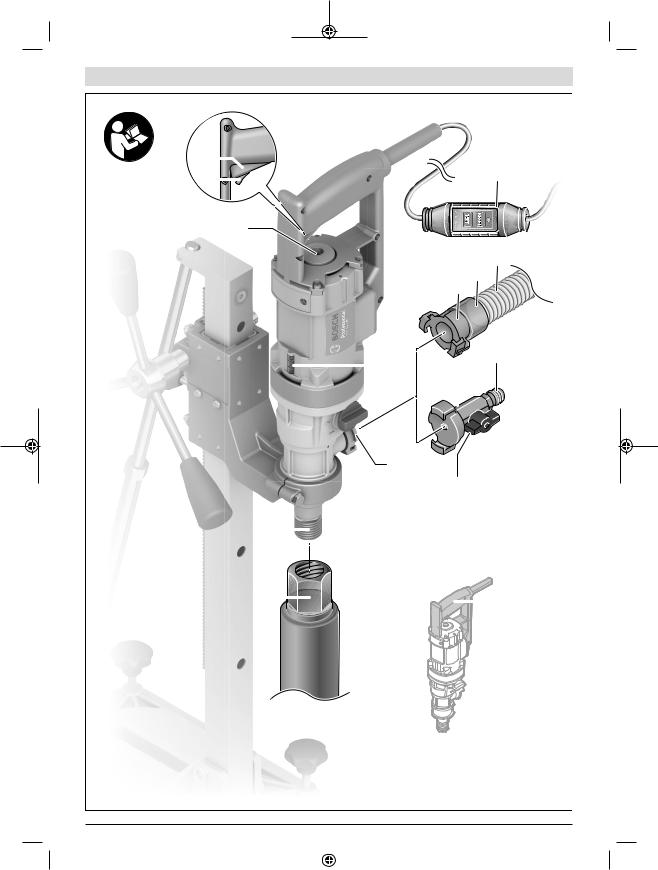
Abgebildete Komponenten
Die Nummerierung der abgebildeten Komponenten bezieht
sich auf die Darstellung von Elektrowerkzeug und Bohrstän-
der auf den Grafikseiten.
Diamantbohrmaschine
(1)Ein-/Ausschalter
(2)Feststelltaste für Ein-/Ausschalter
(3)Libelle für senkrechtes Ausrichten
(4)Libelle für waagerechtes Ausrichten
(5)Gangwahlschalter
(6)Klauenkupplung
(7)Bohrspindel
(8)BohrkroneA)
(9)Handgriff (isolierte Grifffläche)
(10)Wasserabsperrhahn
(11)Hahnanschlussstück
(12)Wasseranschlussadapter
(13)Absaugadapter
(14)AbsaugstutzenA)
(15)AbsaugschlauchA)
(16)Fehlerstromschutzschalter (PRCD)
A)Abgebildetes oder beschriebenes Zubehör gehört nicht zum Standard-Lieferumfang. Das vollständige Zubehör finden Sie in unserem Zubehörprogramm.
Diamantbohrständer
(17)Drehkreuz (isolierte Grifffläche)
(18)Schraube an der Geräteaufnahme
(19)Geräteaufnahme
(20)Bohrsäule
(21)Obere Schraube der Bohrwinkel-Verstellung
(22)Nivellierschraube
(23)WassersammelringA)
(24)Untere Schraube der Bohrwinkel-Verstellung
(25)Bodenplatte
(26)Zahnstange
(27)Spannmutter der Bohrwinkel-Verstellung
(28)Vorschubritzel
(29)Feststellbremse
(30)Mauerwerksdübel/BetondübelA)
(31)SchnellspannspindelA)
(32)Flügelmutter der SchnellspannspindelA)
(33)Spannfeder des WassersammelringsA)
(34)Gleitführungen
(35)Sechskantmutter der Gleitführungen (10 Stück)
Deutsch | 9
(36)Gewindestift der Gleitführungen (10 Stück)
A)Abgebildetes oder beschriebenes Zubehör gehört nicht zum Standard-Lieferumfang. Das vollständige Zubehör finden Sie in unserem Zubehörprogramm.
Technische Daten
Transportable Diamantbohrmaschine
GDB 180 WE + GCR 180
Diamantbohrmaschine |
|
GDB 180 WE |
||||
Sachnummer |
|
3 601 A89 8.. |
||||
Nennaufnahmeleistung |
W |
2000 |
||||
Abgabeleistung |
W |
1340 |
||||
Nenndrehzahl n0 |
|
|
|
|
|
|
– |
1. Gang |
min−1 |
900 |
|||
– |
2. Gang |
min−1 |
2800 |
|||
Bohrdurchmesser |
|
|
|
|
|
|
– |
in Mauerwerk optimal |
mm |
40–180 |
|||
– |
in Mauerwerk möglich |
mm |
0–180 |
|||
– |
in Beton optimal |
mm |
40–150 |
|||
– |
in Beton möglich |
mm |
0–180 |
|||
Werkzeugaufnahme |
|
1 1/4" UNC |
||||
max. Druck Wasser- |
bar |
3 |
||||
versorgung |
|
|
|
|
|
|
Gewicht entsprechend |
kg |
5,2 |
||||
EPTA-Procedure 01:2014 |
|
|
|
|
|
|
Schutzklasse |
|
|
|
|
/I |
|
|
|
|
|
|||
|
|
|
|
|
|
|
Die Angaben gelten für eine Nennspannung [U] von 230 V. Bei abweichenden Spannungen und in länderspezifischen Ausführungen können diese Angaben variieren.
Diamantbohrständer |
|
GCR 180 |
|
Sachnummer |
|
3 601 A90 100 |
|
Maße |
|
|
|
– Höhe |
mm |
767 |
|
– |
Breite |
mm |
205 |
– |
Tiefe |
mm |
423,5 |
Durchmesser Geräteaufnah- |
mm |
60 |
|
me |
|
|
|
Maße Bohrkrone max. |
|
|
|
– |
Durchmesser |
mm |
180 |
– Durchmesser mit Wasser- |
mm |
132 |
|
|
sammelring |
|
|
– Länge |
mm |
530 |
|
Bohrhub max. |
mm |
514 |
|
Arbeitslänge max. |
mm |
455 |
|
Gewicht entsprechend |
kg |
9,5 |
|
EPTA-Procedure 01:2014 |
|
|
|
Bosch Power Tools |
|
|
|
1 609 92A 4NJ | (03.04.2019) |
|
|
|
|
|
|
|
|
|
|
|
|
|
|
|
|
|
|
|
10 | Deutsch
Geräuschinformation
Geräuschemissionswerte ermittelt entsprechend
EN 62841 3 6.
Der A-bewertete Geräuschpegel des Elektrowerkzeugs beträgt typischerweise: Schalldruckpegel 88 dB(A); Schallleistungspegel 99 dB(A). Unsicherheit K=3 dB.
Gehörschutz tragen!
Der in diesen Anweisungen angegebene Geräuschemissionswert ist entsprechend einem genormten Messverfahren gemessen worden und kann für den Vergleich von Elektrowerkzeugen miteinander verwendet werden. Er eignet sich auch für eine vorläufige Einschätzung der Geräuschemission.
Der angegebene Geräuschemissionswert repräsentiert die hauptsächlichen Anwendungen des Elektrowerkzeugs. Wenn allerdings das Elektrowerkzeug für andere Anwendungen, mit abweichenden Einsatzwerkzeugen oder ungenügender Wartung eingesetzt wird, kann der Geräuschemissionswert abweichen. Dies kann die Geräuschemission über den gesamten Arbeitszeitraum deutlich erhöhen.
Für eine genaue Abschätzung der Geräuschemissionen sollten auch die Zeiten berücksichtigt werden, in denen das Gerät abgeschaltet ist oder zwar läuft, aber nicht tatsächlich im Einsatz ist. Dies kann die Geräuschemissionen über den gesamten Arbeitszeitraum deutlich reduzieren.
Montage
uZiehen Sie vor allen Arbeiten am Elektrowerkzeug den Netzstecker aus der Steckdose.
Bohrständer montieren
Bohrsäule aufrichten
Bringen Sie die Bohrsäule (20) in die senkrechte Position. Setzen Sie die untere Schraube (24) ein (siehe Abbildung auf der Grafikseite). Ziehen Sie die untere Schraube (24) und die obere Schraube (21) mit einem Gabelschlüssel (Schlüsselweite 17 mm) fest. Ziehen Sie die Spannmutter (27) mit einem Gabelschlüssel (Schlüsselweite 24 mm) fest.
Drehkreuz
Schrauben Sie die drei Griffstangen des Drehkreuzes (17) bis zum Anschlag in die Mittelnabe des Drehkreuzes.
Das Drehkreuz (17) dient als Vorschubkurbel beim Bohren. Zum Bohren schieben Sie das Drehkreuz je nach Bedarf links oder rechts bis zum Anschlag auf das Vorschubritzel (28).
Zum Abnehmen des Drehkreuzes ziehen Sie dieses kräftig ab.
Vorschubarretierung mit Feststellbremse
Schrauben Sie vor der ersten Inbetriebnahme die Feststellbremse (29) in die freie Gewindebohrung unterhalb des Vorschubritzels (28) ein.
Arretieren Sie für alle Arbeiten am Bohrständer, in Arbeitspausen sowie bei Nichtgebrauch den Vorschub. Drehen Sie dafür die Feststellbremse (29) an.
Lösen Sie zum Bohren die Feststellbremse (29) so weit, dass sich das Drehkreuz (17) leicht bewegen lässt. Halten Sie dabei das Drehkreuz fest, um ein unkontrolliertes Herabgleiten des Elektrowerkzeugs zu verhindern.
Elektrowerkzeug einsetzen (siehe Bild A)
Achten Sie darauf, dass die Feststellbremse (29) angezogen ist.
Lösen Sie die Schraube (18) an der Geräteaufnahme mit einem Gabelschlüssel (Schlüsselweite 13 mm). Setzen Sie das Elektrowerkzeug mit dem Spannhals von oben bis zum Anschlag in die Geräteaufnahme (19) ein.
Drehen Sie das Elektrowerkzeug in der Geräteaufnahme so, dass alle Schalter gut erreichbar sind und der Anschluss der Staubabsaugung/Wasserkühlung am Elektrowerkzeug den Bohrvorgang nicht behindert. Ziehen Sie die Schraube (18) mit dem Gabelschlüssel (Schlüsselweite 13 mm) an. Schieben Sie das Drehkreuz (17) für den Bohrvorgang rechts oder links auf das Vorschubritzel (28).
uKontrollieren Sie den festen Sitz des Elektrowerkzeugs in der Geräteaufnahme.
Gehen Sie beim Entnehmen des Elektrowerkzeugs aus dem Bohrständer in umgekehrter Reihenfolge vor.
Bohrständer befestigen
Hinweis: Befestigen Sie den Bohrständer spielfrei. So vermeiden Sie ein Verklemmen der Bohrkrone und damit Segmentabriss.
Befestigen Sie je nach Art und Beschaffenheit des Untergrundes den Bohrständer mit Dübel oder Vakuum am geplanten Bohrloch.
Bohrständer vor der Befestigung positionieren
Zeichnen Sie die gewünschte Bohrlochmitte am Untergrund an. Markieren Sie die Außenmaße der Bohrkrone, mit der Sie bohren wollen, mit der Bohrlochmitte als Zentrum.
Befestigen Sie den Bohrständer (mit eingesetztem Elektrowerkzeug) mit Dübel oder Vakuum so, dass die montierte Bohrkrone mit den angezeichneten Maßen deckungsgleich ist.
Befestigung mit Dübel (siehe Bild B)
Bohren Sie für die Befestigung des Bohrständers mit Dübel (Zubehör) in Mauerwerk oder Beton ein separates Befestigungsloch.
Abstand Dübelloch – Mitte des geplanten Bohrlochs
optimal |
|
210 mm |
|
möglich |
|
200–300 mm |
|
Für das Dübelloch gelten folgende |
Maße: |
|
|
|
|
|
|
|
Durchmesser |
Tiefe |
|
Mauerwerk |
20 mm |
85 mm |
|
Beton |
16 mm |
50 mm |
|
Setzen Sie einen Betondübel mit Spreizkeil bzw. einen Mau-
erwerksdübel (30) ein. Schrauben Sie die Schnellspann-
spindel (31) in den Dübel.
1 609 92A 4NJ | (03.04.2019) |
|
|
|
Bosch Power Tools |
|
|
|
|
|
|
|
|
|
|
|
|
|
|
|
|
|
|
|
Setzen Sie den Bohrständer sowie eine Unterlegscheibe auf und schrauben Sie sie mit der Flügelmutter (32) an. Ziehen Sie die Flügelmutter nach der Nivellierung mit einem Gabelschlüssel (Schlüsselweite 27 mm) fest.
Befestigung mit Vakuum (Zubehör)
Für die Befestigung des Bohrständers mit Vakuum benötigen Sie eine handelsübliche Vakuumpumpe und ein Bosch-Vaku- umset (Zubehör).
Die Vakuumpumpe muss folgende Mindestanforderungen erfüllen:
Volumenstrom: |
6 m3/h |
Vakuum mindestens: |
80 % (−800 mbar) |
Für die Befestigung mit Vakuum muss der Untergrund glatt und eben sein. Der Einsatz auf Putz oder Mauerwerk ist nicht gestattet.
Setzen Sie, nachdem die Vakuumverbindung hergestellt ist, die Nivellierschrauben (22) leicht auf den Untergrund auf, damit der Bohrständer starr sitzt und der Dichtring leicht entspannt. Ansonsten sitzt der Bohrständer sehr weich auf dem Dichtring.
Für den Anschluss von Vakuumpumpe und Bosch-Vakuum- set lesen und befolgen Sie deren Betriebsanleitungen.
uDie Sicherheitsund Arbeitshinweise für Vakuumpumpe und Vakuumset sind strikt zu beachten!
Nivellieren (nicht bei Befestigung mit Vakuum)
Drehen Sie die Nivellierschrauben (22) einzeln so weit ein bzw. heraus, bis die Libelle (3) am Elektrowerkzeug (bei senkrechter Montage) bzw. die Libelle (4) am Elektrowerkzeug (bei waagerechter Montage) exakt ausgerichtet ist. Fixieren Sie nun den Bohrständer fest mit Dübelbefestigung.
Bohrkrone einsetzen/wechseln
uSichern Sie vor allen Arbeiten an Bohrständer oder Bohrmaschine, in Arbeitspausen sowie bei Nichtgebrauch den Bohrständer durch Festdrehen der Feststellbremse gegen unbeabsichtigtes Bewegen.
Bohrkrone auswählen
Bosch-Bohrkronen haben eine Farb-Kodierung:
–Nassbohrkronen: blau
–Trockenbohrkronen: hellgrau
Bohrkrone einsetzen
uPrüfen Sie die Bohrkronen vor dem Einsetzen. Setzen Sie nur einwandfreie Bohrkronen ein. Beschädigte oder deformierte Bohrkronen können zu gefährlichen Situationen führen.
Reinigen Sie die Bohrkrone vor dem Einsetzen. Fetten Sie das Gewinde der Bohrkrone leicht oder sprühen Sie es mit Korrosionsschutz ein.
Schrauben Sie eine 1 1/4"-UNC-Bohrkrone (8) auf die Bohrspindel (7) auf.
uPrüfen Sie die Bohrkrone auf festen Sitz. Falsch oder nicht sicher befestigte Bohrkronen können sich während des Betriebs lösen und Sie gefährden.
Deutsch | 11
Bohrkrone entnehmen
uTragen Sie beim Wechseln der Bohrkrone Schutzhandschuhe. Die Bohrkrone kann bei längerem Betrieb des Elektrowerkzeugs heiß werden.
Lösen Sie die Bohrkrone (8) mit einem Gabelschlüssel (Schlüsselweite 41 mm). Halten Sie dabei mit einem zweiten Gabelschlüssel (Schlüsselweite 32 mm) am Zweikant der Bohrspindel (7) gegen.
Wasserkühlung/Staubabsaugung anschließen
Werden Nassoder Trockenbohrkronen beim Bohren nicht ausreichend gekühlt, können die Diamantsegmente beschädigt werden, oder die Bohrkrone kann in der Bohrung blockieren. Achten Sie deshalb beim Nassbohren auf ausreichende Wasserkühlung, beim Trockenbohren auf eine funktionierende Staubabsaugung.
Bei der Vergrößerung einer vorhandenen Bohrung muss diese sorgfältig verschlossen werden, um eine ausreichende Kühlung der Bohrkrone zu ermöglichen.
uAngeschlossene Schläuche, Absperrventile oder Zubehör dürfen den Bohrvorgang nicht behindern.
Wasserkühlung anschließen
Setzen Sie den Wasseranschlussadapter (12) auf die Klauenkupplung (6) und drehen Sie ihn im Uhrzeigersinn bis zum Anschlag fest.
Drehen Sie den Wasserabsperrhahn (10) zu. Schließen Sie eine Wasserzuleitung an das Hahnanschlussstück (11) an. Die Wasserzuleitung ist aus einem mobilen Wasserdruckbehälter (Zubehör) oder von einem stationären Wasseranschluss möglich.
Um das beim Nassbohren aus der Bohrung austretende Wasser aufzufangen, benötigen Sie einen Wassersammelring und einen Nass-/Trockensauger (beide Zubehör).
Wassersammelring zur Wasserabsaugung montieren
(siehe Bild C)
Der Wassersammelring (siehe „Zubehör/Ersatzteile“, Seite 14) ist für die Verwendung mit dem Diamantbohrständer
GCR 180 und der Diamantbohrmaschine GDB 180 WE vorgesehen.
Schneiden Sie eine Öffnung für den gewünschten Bohrdurchmesser in den Dichtungsdeckel.
Schieben Sie die Spannfeder (33) bis zum Anschlag in den Spalt zwischen Bodenplatte (25) und Bohrsäule (20). Achten Sie darauf, dass der abgewinkelte Teil der Spannfeder nach unten zeigt.
Bringen Sie den Wassersammelring in Position und legen Sie die Spannfeder auf die Auflagepunkte am Wassersammelring. (Die Laschen an den Enden der Spannfeder dienen zum Ziehen der Spannfeder nach oben.)
Durch die Spannkraft der Feder wird der Wassersammelring mit seiner Dichtung auf den Untergrund gedrückt und verhindert zusammen mit dem Vakuum des Nass-/Trockensaugers den Wasseraustritt.
Bosch Power Tools |
|
|
|
1 609 92A 4NJ | (03.04.2019) |
|
|
|
|
|
|
|
|
|
|
|
|
|
|
|
|
|
|
|

12 | Deutsch
Staubabsaugung anschließen
Stäube von Materialien wie bleihaltigem Anstrich, einigen Holzarten, Mineralien und Metall können gesundheitsschädlich sein. Berühren oder Einatmen der Stäube können allergische Reaktionen und/oder Atemwegserkrankungen des Benutzers oder in der Nähe befindlicher Personen hervorrufen. Bestimmte Stäube wie Eichenoder Buchenstaub gelten als krebserzeugend, besonders in Verbindung mit Zusatzstoffen zur Holzbehandlung (Chromat, Holzschutzmittel). Asbesthaltiges Material darf nur von Fachleuten bearbeitet werden.
–Benutzen Sie möglichst eine für das Material geeignete Staubabsaugung.
–Sorgen Sie für gute Belüftung des Arbeitsplatzes.
–Es wird empfohlen, eine Atemschutzmaske mit Filterklasse P2 zu tragen.
Beachten Sie in Ihrem Land gültige Vorschriften für die zu bearbeitenden Materialien.
Setzen Sie den Absaugadapter (13) auf die Klauenkupplung (6) und drehen Sie ihn im Uhrzeigersinn bis zum Anschlag fest.
Stecken Sie den Absaugschlauch (15) eines auf dieses System abgestimmten und empfohlenen Nass-/Trockensaugers (siehe „Zubehör/Ersatzteile“, Seite 14) auf den Absaugstutzen (14).
Betrieb
Bohrwinkel ändern
uZiehen Sie vor allen Arbeiten am Elektrowerkzeug den Netzstecker aus der Steckdose.
uZiehen Sie nach jeder Verstellung am Bohrständer alle Schrauben wieder fest.
Lösen Sie die untere Schraube (24) der Bohrwinkel-Verstel- lung mit einem Gabelschlüssel (Schlüsselweite 17 mm) und nehmen Sie sie ab.
Lösen Sie die obere Schraube (21) mit einem Gabelschlüssel (Schlüsselweite 17 mm).
Lösen Sie die Spannmutter (27) mit einem Gabelschlüssel (Schlüsselweite 24 mm). Stellen Sie den Bohrständer auf den gewünschten Bohrwinkel.
Ziehen Sie die Spannmutter (27) mit dem Gabelschlüssel (Schlüsselweite 24 mm) wieder fest an. Ziehen Sie die obere Schraube (21) mit einem Gabelschlüssel (Schlüsselweite 17 mm) fest.
uDer Bohrständer darf erst eingesetzt werden, wenn Spannmutter (27) und Schraube (21) der Winkelverstellung wieder festgezogen sind.
Nach dem Bohren bringen Sie die Bohrsäule (20) in umgekehrter Reihenfolge wieder in die senkrechte Position (Bohrwinkel von 0°). Dazu müssen Sie die untere Schraube (24) wieder einsetzen und mit einem Gabelschlüssel (Schlüsselweite 17 mm) festziehen.
Inbetriebnahme
uBeachten Sie die Netzspannung! Die Spannung der Stromquelle muss mit den Angaben auf dem Typenschild des Elektrowerkzeuges übereinstimmen.
uZiehen Sie vor Arbeitsbeginn den verantwortlichen Statiker, Architekten oder die zuständige Bauleitung über geplante Bohrungen zurate. Durchtrennen Sie Armierungen nur mit Genehmigung eines Baustatikers.
uKontrollieren Sie bei Bohrungen, die Wände oder den Boden durchbohren, unbedingt die betroffenen Räume auf Hindernisse. Sperren Sie die Baustelle ab und sichern Sie den Bohrkern mittels Schalung gegen Herunterfallen.
Funktionstest des Fehlerstromschutzschalters (PRCD)
Überprüfen Sie die ordnungsgemäße Funktion des Fehlerstromschutzschalters (PRCD) (16) vor jedem Arbeitsbeginn:
–Drücken Sie die TEST-Taste am Fehlerstromschutzschalter (PRCD). Die rote Kontrollanzeige erlischt.
–Drücken Sie die RESET-Taste. Das Elektrowerkzeug muss sich jetzt einschalten lassen.
Erlischt die rote Kontrollanzeige nicht, wenn Sie die TEST- Taste drücken, oder erlischt sie beim Einschalten des Elektrowerkzeugs wiederholt, dann müssen Sie das Elektrowerkzeug bei einer autorisierten Bosch-Kundendienststelle überprüfen lassen.
uIst der Fehlerstromschutzschalter (PRCD) defekt, darf das Elektrowerkzeug nicht betrieben werden.
Einschalten
Drücken Sie die RESET-Taste am Fehlerstromschutzschalter (PRCD) (16).
Nassbohren: Stellen Sie den Wasserabsperrhahn (10) auf Durchfluss.
Zum Einschalten des Elektrowerkzeugs drücken Sie den Ein-/Ausschalter (1) und halten Sie ihn gedrückt.
Zum Arretieren des gedrückten Ein-/Ausschalters drücken Sie zusätzlich die Feststelltaste (2).
Ausschalten
Lassen Sie den Ein-/Ausschalter (1) los. Bei arretiertem Ein-/Ausschalter drücken Sie diesen zuerst und lassen ihn danach los.
Nassbohren: Drehen Sie den Wasserabsperrhahn (10) zu. Trennen Sie nach Arbeitsende das Hahnanschlussstück (11) von der Wasserzuleitung. Öffnen Sie den Wasserabsperrhahn (10) und lassen Sie das Restwasser ab.
Anlaufstrombegrenzung
Die Elektronik des Elektrowerkzeugs lässt den Motor sanft starten und verhindert damit einen zu hohen Anlaufstrom.
Wiederanlaufschutz
Der Wiederanlaufschutz verhindert das unkontrollierte Anlaufen des Elektrowerkzeugs nach einer Unterbrechung der Stromzufuhr.
1 609 92A 4NJ | (03.04.2019) |
|
|
|
Bosch Power Tools |
|
|
|
|
|
|
|
|
|
|
|
|
|
|
|
|
|
|
|

Zur Wiederinbetriebnahme drücken Sie die RESET-Taste am Fehlerstromschutzschalter (PRCD) (16). Bringen Sie anschließend den Ein-/Ausschalter (1) in die ausgeschaltete Position und schalten das Elektrowerkzeug erneut ein.
Drehzahl vorwählen
Mit dem Gangwahlschalter (5) können zwei Drehzahlen vorgewählt werden.
Die Gänge werden für folgende Bohrdurchmesser empfohlen:
–1. Gang: 80–180 mm
–2. Gang: 25–60 mm
Arbeitshinweise
uZiehen Sie vor allen Arbeiten am Elektrowerkzeug den Netzstecker aus der Steckdose.
Lösen Sie zum Bohren die Feststellbremse (29) so weit, dass sich das Drehkreuz (17) leicht bewegen lässt. Halten Sie dabei das Drehkreuz fest, um ein unkontrolliertes Herabgleiten des Elektrowerkzeugs zu verhindern.
Bohren Sie im 1. Gang mit geringer Drehzahl an, bis sich die Bohrkrone vibrationsfrei im Werkstoff dreht. Schalten Sie danach gegebenenfalls in den 2. Gang.
Passen Sie den Anpressdruck beim Bohren dem zu bohrenden Werkstoff an. Bohren Sie mit gleichmäßigem Druck. Ziehen Sie die Bohrkrone gelegentlich leicht aus der Bohrung zurück, damit der Bohrschlamm bzw. -staub aus den Diamantsegmenten entfernt wird.
Drehen Sie mit dem Drehkreuz (17) das Elektrowerkzeug bis zur gewünschten Bohrtiefe herunter. Drehen Sie danach zurück, bis die Bohrkrone vollständig sichtbar ist.
Um die maximal mögliche Arbeitslänge zu erreichen, müssen Sie den Bohrkern entfernen, sobald er die Bohrkrone komplett ausfüllt. Führen Sie dann die Bohrkrone erneut in das Bohrloch ein und bohren Sie bis zur Maximaltiefe.
Überlastkupplung
Klemmt oder hakt die Bohrkrone, wird der Antrieb der Bohrspindel unterbrochen. Schalten Sie in diesem Fall das Elektrowerkzeug umgehend aus, um Verschleiß und Wärmeentwicklung zu vermeiden.
Lösen Sie die Bohrkrone durch Drehen mit einem passenden Gabelschlüssel nach rechts und links. Ziehen Sie dabei das Elektrowerkzeug vorsichtig aus dem Bohrloch.
Überlastschutz
Wird die Überlastschwelle überschritten, dann beginnt das Elektrowerkzeug deutlich zu pulsieren. Verringern Sie den Anpressdruck, bis das Elektrowerkzeug wieder normal arbeitet.
Wird der Anpressdruck nicht verringert, dann schaltet sich das Elektrowerkzeug ab. Sie können das Elektrowerkzeug danach sofort wieder einschalten, sollten aber mit verringertem Anpressdruck weiterarbeiten.
Bohrkern entfernen
Nassbohren: Lassen Sie das Wasser nach dem Bohren kurz weiterlaufen, um den Bohrschlamm zwischen Bohrkrone und Bohrkern herauszuspülen.
Deutsch | 13 |
Sitzt der Bohrkern in der Bohrkrone fest, dann schlagen Sie mit einem weichen Holz oder Kunststoffstück auf die Bohrkrone und lösen so den Bohrkern. Drücken Sie bei Bedarf den Bohrkern mit einem Stab durch das Einsteckende der Bohrkrone heraus.
Hinweis: Schlagen Sie nicht mit harten Gegenständen auf die Bohrkrone (Deformationsgefahr)!
Wartung und Service
Wartung und Reinigung
uZiehen Sie vor allen Arbeiten am Elektrowerkzeug den Netzstecker aus der Steckdose.
uHalten Sie das Elektrowerkzeug und die Lüftungsschlitze sauber, um gut und sicher zu arbeiten.
Halten Sie die Zahnstange (26) und die Führungsflächen der Bohrsäule (20) stets sauber.
Säubern Sie die Bohrspindel (7) nach Arbeitsende. Sprühen Sie die Bohrspindel und die Bohrkrone (8) gelegentlich mit Korrosionsschutzmittel ein.
Wenn ein Ersatz der Anschlussleitung erforderlich ist, dann ist dies von Bosch oder einer autorisierten Kundendienststelle für Bosch-Elektrowerkzeuge auszuführen, um Sicherheitsgefährdungen zu vermeiden.
Gleitführungen nachjustieren (siehe Bild D)
Im Lauf der Zeit können die Gleitführungen (34) verschleißen und es tritt Spiel zwischen den Gleitführungen und der Bohrsäule auf. Um dieses Spiel zu beseitigen, müssen Sie die Gleitführungen nachjustieren.
Lösen Sie alle zehn Sechskantmuttern (35) mit einem Gabelschlüssel (Schlüsselweite 13 mm). Ziehen Sie anschließend die Gewindestifte (36) gleichmäßig an, bis das Spiel minimiert ist. Ziehen Sie alle zehn Sechskantmuttern wieder fest.
Ein Wechsel der Gleitführungen ist erst dann erforderlich, wenn die Gleitschicht (rote Farbe) verschlissen ist. Das ist dann der Fall, wenn die rote Farbe verschwunden ist und das Trägermaterial zum Vorschein kommt. Es wird empfohlen, den Wechsel von einer autorisierten Kundendienststelle für
Bosch-Elektrowerkzeuge durchführen zu lassen.
Transport
Sie können den Bohrständer mit eingesetztem Elektrowerkzeug abstellen. Drehen Sie dazu das Elektrowerkzeug mit
Bosch Power Tools |
|
|
|
1 609 92A 4NJ | (03.04.2019) |
|
|
|
|
|
|
|
|
|
|
|
|
|
|
|
|
|
|
|
14 | English
dem Drehkreuz (17) so weit wie möglich in Richtung Bodenplatte, um die Kippgefahr zu verringern.
Zum sicheren Transport entnehmen Sie das Elektrowerkzeug aus dem Bohrständer.
Zubehör/Ersatzteile
Wassersammelring (GCR 180) |
2 608 550 621 |
|
Dichtungsdeckel für Wassersammelring |
2 608 550 624 |
|
(GCR 180) |
|
|
Befestigungsset: |
|
|
– |
für Beton |
2 608 002 000 |
– |
für Mauerwerk |
2 607 000 745 |
Dübelset für Beton |
2 608 002 001 |
|
Vakuumset |
2 608 550 623 |
|
Dichtungsgummi für Vakuumset |
2 608 550 625 |
|
(GCR 180) |
|
|
Wasserdruckbehälter |
2 609 390 308 |
|
Adapter G 1/2" |
2 608 598 043 |
|
Nass-/Trockensauger GAS 35MAFC |
|
|
Nass-/Trockensauger GAS 55MAFC |
|
|
Unter www.bosch-pt.com/ch/de können Sie online Ersatz-
teile bestellen.
Tel.: (044) 8471511
Fax: (044) 8471551
E-Mail: Aftersales.Service@de.bosch.com
Luxemburg
Tel.: +32 2 588 0589
Fax: +32 2 588 0595
E-Mail: outillage.gereedschap@be.bosch.com
Entsorgung
Elektrowerkzeuge, Bohrständer, Zubehör und Verpackungen sollen einer umweltgerechten Wiederverwertung zugeführt werden.
Werfen Sie Elektrowerkzeuge nicht in den
Hausmüll!
Nur für EU-Länder:
Gemäß der Europäischen Richtlinie 2012/19/EU über Elektro- und Elektronik-Altgeräte und ihrer Umsetzung in nationales Recht müssen nicht mehr gebrauchsfähige Elektrowerkzeuge getrennt gesammelt und einer umweltgerechten Wiederverwertung zugeführt werden.
Kundendienst und Anwendungsberatung
Der Kundendienst beantwortet Ihre Fragen zu Reparatur und Wartung Ihres Produkts sowie zu Ersatzteilen. Explosionszeichnungen und Informationen zu Ersatzteilen finden Sie auch unter: www.bosch-pt.com
Das Bosch-Anwendungsberatungs-Team hilft Ihnen gerne bei Fragen zu unseren Produkten und deren Zubehör. www.powertool-portal.de, das Internetportal für Handwerker und Heimwerker.
Geben Sie bei allen Rückfragen und Ersatzteilbestellungen bitte unbedingt die 10-stellige Sachnummer laut Typenschild des Produkts an.
Deutschland
Robert Bosch Power Tools GmbH
Servicezentrum Elektrowerkzeuge
Zur Luhne 2
37589 Kalefeld – Willershausen
Unter www.bosch-pt.de können Sie online Ersatzteile bestellen oder Reparaturen anmelden.
Kundendienst: Tel.: (0711) 40040460
Fax: (0711) 40040461
E-Mail: Servicezentrum.Elektrowerkzeuge@de.bosch.com
Anwendungsberatung:
Tel.: (0711) 40040460
Fax: (0711) 40040462
E-Mail: kundenberatung.ew@de.bosch.com
Österreich
Unter www.bosch-pt.at können Sie online Ersatzteile bestellen.
Tel.: (01) 797222010
Fax: (01) 797222011
E-Mail: service.elektrowerkzeuge@at.bosch.com
Schweiz
English
Safety instructions
General Power Tool Safety Warnings
 WARNING Read all safety warnings, instructions, illustrations and specifica-
tions provided with this power tool. Failure to follow all in-
structions listed below may result in electric shock, fire and/
or serious injury.
Save all warnings and instructions for future reference.
The term "power tool" in the warnings refers to your mainsoperated (corded) power tool or battery-operated (cordless) power tool.
WARNING ! When using electric tools basic safety precautions should always be followed to reduce the risk of fire, electric shock and personal injury including the following. Read all these instructions before attempting to operate this product and save these instructions.
Work area safety
uKeep work area clean and well lit. Cluttered or dark areas invite accidents.
uDo not operate power tools in explosive atmospheres, such as in the presence of flammable liquids, gases or
1 609 92A 4NJ | (03.04.2019) |
|
|
|
Bosch Power Tools |
|
|
|
|
|
|
|
|
|
|
|
|
|
|
|
|
|
|
|

dust. Power tools create sparks which may ignite the dust
or fumes.
uKeep children and bystanders away while operating a power tool. Distractions can cause you to lose control.
Electrical safety
uPower tool plugs must match the outlet. Never modify the plug in any way. Do not use any adapter plugs with earthed (grounded) power tools. Unmodified plugs and matching outlets will reduce risk of electric shock.
uAvoid body contact with earthed or grounded surfaces, such as pipes, radiators, ranges and refrigerators. There is an increased risk of electric shock if your body is earthed or grounded.
uDo not expose power tools to rain or wet conditions.
Water entering a power tool will increase the risk of electric shock.
uDo not abuse the cord. Never use the cord for carrying, pulling or unplugging the power tool. Keep cord away from heat, oil, sharp edges or moving parts.
Damaged or entangled cords increase the risk of electric shock.
uWhen operating a power tool outdoors, use an extension cord suitable for outdoor use. Use of a cord suitable for outdoor use reduces the risk of electric shock.
uIf operating a power tool in a damp location is unavoidable, use a residual current device (RCD) protected supply. Use of an RCD reduces the risk of electric shock.
Personal safety
uStay alert, watch what you are doing and use common sense when operating a power tool. Do not use a power tool while you are tired or under the influence of drugs, alcohol or medication. A moment of inattention while operating power tools may result in serious personal injury.
uUse personal protective equipment. Always wear eye protection. Protective equipment such as a dust mask, non-skid safety shoes, hard hat or hearing protection used for appropriate conditions will reduce personal injuries.
uPrevent unintentional starting. Ensure the switch is in the off-position before connecting to power source and/or battery pack, picking up or carrying the tool.
Carrying power tools with your finger on the switch or energising power tools that have the switch on invites accidents.
uRemove any adjusting key or wrench before turning the power tool on. A wrench or a key left attached to a rotating part of the power tool may result in personal injury.
uDo not overreach. Keep proper footing and balance at all times. This enables better control of the power tool in unexpected situations.
uDress properly. Do not wear loose clothing or jewellery. Keep your hair and clothing away from moving
English | 15
parts. Loose clothes, jewellery or long hair can be caught in moving parts.
uIf devices are provided for the connection of dust extraction and collection facilities, ensure these are connected and properly used. Use of dust collection can reduce dust-related hazards.
uDo not let familiarity gained from frequent use of tools allow you to become complacent and ignore tool safety principles. A careless action can cause severe injury within a fraction of a second.
Power tool use and care
uDo not force the power tool. Use the correct power tool for your application. The correct power tool will do the job better and safer at the rate for which it was designed.
uDo not use the power tool if the switch does not turn it on and off. Any power tool that cannot be controlled with the switch is dangerous and must be repaired.
uDisconnect the plug from the power source and/or remove the battery pack, if detachable, from the power tool before making any adjustments, changing accessories, or storing power tools. Such preventive safety measures reduce the risk of starting the power tool accidentally.
uStore idle power tools out of the reach of children and do not allow persons unfamiliar with the power tool or these instructions to operate the power tool. Power tools are dangerous in the hands of untrained users.
uMaintain power tools and accessories. Check for misalignment or binding of moving parts, breakage of parts and any other condition that may affect the power tool’s operation. If damaged, have the power tool repaired before use. Many accidents are caused by poorly maintained power tools.
uKeep cutting tools sharp and clean. Properly maintained cutting tools with sharp cutting edges are less likely to bind and are easier to control.
uUse the power tool, accessories and tool bits etc. in accordance with these instructions, taking into account the working conditions and the work to be performed. Use of the power tool for operations different from those intended could result in a hazardous situation.
uKeep handles and grasping surfaces dry, clean and free from oil and grease. Slippery handles and grasping surfaces do not allow for safe handling and control of the tool in unexpected situations.
Service
uHave your power tool serviced by a qualified repair person using only identical replacement parts. This will ensure that the safety of the power tool is maintained.
Diamond drill safety warnings
uWhen performing drilling that requires the use of water, route the water away from the operator’s work area or use a liquid collection device. Such precaution-
Bosch Power Tools |
|
|
|
1 609 92A 4NJ | (03.04.2019) |
|
|
|
|
|
|
|
|
|
|
|
|
|
|
|
|
|
|
|
16 | English
ary measures keep the operator’s work area dry and reduce the risk of electrical shock.
uOperate power tool by insulated grasping surfaces, when performing an operation where the cutting accessory may contact hidden wiring or its own cord.
Cutting accessory contacting a “live” wire may make exposed metal parts of the power tool “live” and could give the operator an electric shock.
uWear hearing protection when diamond drilling. Exposure to noise can cause hearing loss.
uWhen the bit is jammed, stop applying downward pressure and turn off the tool. Investigate and take corrective actions to eliminate the cause of the bit jamming.
uWhen restarting a diamond drill in the workpiece check that the bit rotates freely before starting. If the bit is jammed, it may not start, may overload the tool, or may cause the diamond drill to release from the workpiece.
uWhen securing the drill stand with anchors and fasteners to the workpiece, ensure that the anchoring used is capable of holding and restraining the machine during use. If the workpiece is weak or porous, the anchor may pull out causing the drill stand to release from the workpiece.
uWhen securing the drill stand with a vacuum pad to the workpiece, install the pad on a smooth, clean, nonporous surface. Do not secure to laminated surfaces such as tiles and composite coating. If the workpiece is not smooth, flat or well affixed, the pad may pull away from the workpiece.
uEnsure there is sufficient vacuum before and during drilling. If the vacuum is insufficient, the pad may release from the workpiece.
uNever perform drilling with the machine secured by the vacuum pad only, except when drilling downwards. If the vacuum is lost, the pad will release from the workpiece.
uWhen drilling through walls or ceilings, ensure to protect persons and the work area on the other side. The bit may extend through the hole or the core may fall out on the other side.
uDo not use this tool for overhead drilling with water supply. Water entering the power tool will increase the risk of electric shock.
uUse suitable detectors to determine if utility lines are hidden in the work area or call the local utility company for assistance. Contact with electric lines can lead to fire and electric shock. Damaging a gas line can lead to explosion. Penetrating a water line causes property damage or may cause an electric shock.
uWear non-skid shoes. This prevents injuries that can occur from slipping on smooth surfaces.
uNever operate the power tool without the portable residual current device (PRCD) included in delivery.
uPay attention that neither persons in the working area nor the power tool itself come into contact with the water that comes out.
uProducts sold in GB only: Never operate the 110 V execution of the machine without isolation transformer according to EN/IEC 61558-1 and EN/IEC 61558-2-23. The isolation transformer must have a grounded earth wire on the secondary winding side.
uNever leave the tool unattended before it has come to a complete stop. Cutting tools that are still running can cause injuries.
uAssemble the drill stand properly before mounting the drill. The correct assembly is important in order to ensure proper function.
uEnsure that the drill is securely attached to the drill stand before using it. Otherwise, the drill may slip in the drill stand, which can lead to a loss of control.
uSecure the drill stand on a stable and even surface. If there is a chance that the drill stand will slip or wobble, the safe and steady operation of the drill cannot be guaranteed.
uKeep the drill cord away from the work area. Damaged or entangled cords increase the risk of electric shock.
uDo not overload the drill stand or climb or stand on it.
Overloading or standing on the drill stand can raise its centre of gravity, causing it to tip over.
uStore idle drill stands out of the reach of children. Do not allow persons unfamiliar with the tool or these instructions to operate the tool. Tools can be dangerous in the hands of untrained users.
uBefore carrying out any work on the drill stand or drill, during work breaks and when not using the drill stand, secure the drill stand against unintentional movement by tightening the parking brake.
uThe power tool must only be operated on a mains supply with protective conductor and adequate dimensioning.
uAlways fasten the drill stand while in operation, using anchors or vacuum (accessory) to prevent accidental tipping of the drill stand with inserted diamond drill and core bit.
uEnsure that water-carrying hoses, connectors and the water collection ring (accessory) are in immaculate condition. Replace damaged or worn parts before the next use. Water escaping from parts of the power tool will increase the risk of electric shock.
Products sold in GB only:
Your product is fitted with an BS 1363/A approved electric plug with internal fuse (ASTA approved to BS 1362).
If the plug is not suitable for your socket outlets, it should be cut off and an appropriate plug fitted in its place by an authorised customer service agent. The replacement plug should have the same fuse rating as the original plug.
The severed plug must be disposed of to avoid a possible shock hazard and should never be inserted into a mains socket elsewhere.
1 609 92A 4NJ | (03.04.2019) |
|
|
|
Bosch Power Tools |
|
|
|
|
|
|
|
|
|
|
|
|
|
|
|
|
|
|
|

Product Description and
Specifications
Read all the safety and general instructions.
Failure to observe the safety and general instructions may result in electric shock, fire and/or serious injury.
Please observe the illustrations at the beginning of this operating manual.
Intended use
Transportable diamond drill GDB 180 WE + GCR 180
Diamond drill
In conjunction with diamond wet-drilling core bits and a water supply, the power tool is intended for wet drilling in concrete and reinforced concrete. The power tool can be combined with a dust extraction attachment (water collection ring and wet/dry extractor).
In conjunction with dry diamond core bits and a suitable dust extraction attachment, the power tool is intended for dry drilling in brick, sandstone, aerated concrete and tiles. When used in a fixed position, the power tool must be held in place by the drill stand for diamond drills GCR 180. Over-
head work is not permitted.
Drill stand for diamond drills
The drill stand for diamond drills is intended for mounting the Bosch diamond drill GDB 180 WE. Other tools may not be used.
The drill stand for diamond drills can be secured to the floor or the wall using an anchor.
The drill stand for diamond drills can be attached to the floor by means of vacuum (accessory) or (with an additional safeguard) against the wall. Attaching overhead is not permitted.
Product features
The numbering of the product features refers to the representation of the power tool and drill stand on the graphic pages.
Diamond drill
(1)On/off switch
(2)Lock-on button for on/off switch
(3)Level for vertical alignment
(4)Level for horizontal alignment
(5)Gear selector switch
(6)Claw coupling
(7)Drill spindle
(8)Core bitA)
(9)Handle (insulated gripping surface)
(10)Water cutoff valve
(11)Valve adapter
(12)Water connection adapter
(13)Extraction adapter
English | 17
(14)Extraction outletA)
(15)Extraction hoseA)
(16)Portable residual current device (PRCD)
A)Accessories shown or described are not included with the product as standard. You can find the complete selection of accessories in our accessories range.
Drill stand for diamond drills
(17)Star handle (insulated gripping surface)
(18)Screw on the drill holder
(19)Drill holder
(20)Drill column
(21)Upper screw of the drilling angle adjuster
(22)Levelling screw
(23)Water collection ringA)
(24)Lower screw of the drilling angle adjuster
(25)Base plate
(26)Rack
(27)Clamping nut of the drilling angle adjuster
(28)Feed pinion
(29)Locking brake
(30)Masonry anchor/concrete anchorA)
(31)Quick-clamping spindleA)
(32)Wing nut for the quick-clamping spindleA)
(33)Tension spring for the water collection ringA)
(34)Sliding guides
(35)Hex nut for sliding guides (x 10)
(36)Threaded pin for sliding guides (x 10)
A)Accessories shown or described are not included with the product as standard. You can find the complete selection of accessories in our accessories range.
Technical data
Transportable diamond drill GDB 180 WE + GCR 180
Diamond drill |
|
GDB 180 WE |
|
Article number |
|
3 601 A89 8.. |
|
Rated power input |
W |
2000 |
|
Power output |
W |
1340 |
|
Rated speed n0 |
|
|
|
– |
First gear |
min−1 |
900 |
– |
Second gear |
min−1 |
2800 |
Drilling diameter |
|
|
|
– |
optimum in masonry |
mm |
40–180 |
– |
possible in masonry |
mm |
0–180 |
– |
optimum in concrete |
mm |
40–150 |
– |
possible in concrete |
mm |
0–180 |
Tool holder |
|
1 1/4" UNC |
|
Max. pressure of water supply |
bar |
3 |
|
Bosch Power Tools |
|
|
|
1 609 92A 4NJ | (03.04.2019) |
|
|
|
|
|
|
|
|
|
|
|
|
|
|
|
|
|
|
|
18 | English
Diamond drill |
|
GDB 180 WE |
|||
Weight according to |
kg |
5.2 |
|||
EPTA-Procedure 01:2014 |
|
|
|
|
|
Protection class |
|
|
|
|
/ I |
|
|
|
|
||
|
|
|
|
|
|
The specifications apply to a rated voltage [U] of 230 V. These specifications may vary at different voltages and in country-specific models.
Drill stand for diamond drills |
|
GCR 180 |
Article number |
|
3 601 A90 100 |
Dimensions |
|
|
– Height |
mm |
767 |
– Width |
mm |
205 |
– Depth |
mm |
423.5 |
Drill holder diameter |
mm |
60 |
Max. dimensions of core bit |
|
|
– Diameter |
mm |
180 |
– Diameter with water collec- |
mm |
132 |
tion ring |
|
|
– Length |
mm |
530 |
Max. drill stroke |
mm |
514 |
Max. working length |
mm |
455 |
Weight according to |
kg |
9.5 |
EPTA-Procedure 01:2014 |
|
|
Assembling the drill stand
Erecting the drill column
Position the drill column (20) so that it is vertical. Insert the lower screw (24) (see illustration on the graphics page). Tighten the lower screw (24) and the upper screw (21) using an open-ended spanner (width across flats 17 mm). Tighten the clamping nut (27) using an open-ended spanner (width across flats 24 mm).
Star handle
Screw the three handlebars of the star handle (17) all the way into the central hub of the star handle.
The star handle (17) acts as the feed crank during drilling. To drill, push the star handle all the way to the left or right (as required) and onto the feed pinion (28). Pull the star handle off firmly to remove it.
Feed lock with locking brake
Before using for the first time, screw the locking brake (29) into the free threaded hole underneath the feed pinion (28). Lock the feed when performing any work on the drill stand, during breaks and when not using the drill stand. Do this by engaging the locking brake (29).
To drill, loosen the locking brake (29) until the star handle (17) is easy to move. When doing so, hold the star
handle in place to prevent the power tool from sliding down in an uncontrolled manner.
Noise information
Noise emission values determined according to
EN 62841 3 6.
Typically, the A-weighted noise level of the power tool is: Sound pressure level 88 dB(A); sound power level
99 dB(A). Uncertainty K=3 dB.
Wear hearing protection
The noise emission value given in these instructions has been measured in accordance with a standardised measuring procedure and may be used to compare power tools. It may also be used for a preliminary estimation of noise emissions.
The noise emission value given represents the main applications of the power tool. However, if the power tool is used for other applications, with different application tools or is poorly maintained, the noise emission value may differ. This may significantly increase noise emissions over the total working period.
To estimate noise emissions accurately, the times when the tool is switched off, or when it is running but not actually being used, should also be taken into account. This may significantly reduce noise emissions over the total working period.
Assembly
uPull the plug out of the socket before carrying out any work on the power tool.
Inserting the power tool (see figure A)
Ensure that the locking brake (29) is engaged.
Loosen the screw (18) on the drill holder using an openended spanner (width across flats 13 mm). Insert the power tool with the collar all the way into the drill holder (19) from above.
Turn the power tool in the drill holder so that all the switches are easy to reach and the dust extraction/water cooling connection on the power tool does not interfere with drilling.
Tighten the screw (18) using the open-ended spanner (width across flats 13 mm).
Slide the star handle (17) to the right or left and onto the feed pinion (28) in order to drill.
uCheck that the power tool is fitted securely in the drill holder.
To remove the power tool from the drill stand, carry out the steps above in reverse order.
Fixing the drill stand in place
Note: Fix the drill stand in place so that it is free of play. This prevents the core bit jamming and segments from being torn out.
Depending on the type and condition of the surface, fasten the drill stand at the planned bore hole using anchors or vacuum.
1 609 92A 4NJ | (03.04.2019) |
|
|
|
Bosch Power Tools |
|
|
|
|
|
|
|
|
|
|
|
|
|
|
|
|
|
|
|
Positioning the drill stand before fixing in place
Mark the centre of the hole you want to drill on the surface. Mark the outer dimensions of the core bit you want to use, using the centre of the hole as the centre of the bit.
Fix the drill stand (with power tool inserted) in place using an anchor or vacuum so that the core bit lines up with the marked dimensions when attached.
Fixing with an anchor (see figure B)
Drill a separate attachment hole for fixing the drill stand in place with an anchor (accessories) in masonry or concrete.
Distance between anchor hole and centre of planned
hole
Optimum |
210 mm |
Possible |
200–300 mm |
The following dimensions apply for the anchor hole:
|
Diameter |
Depth |
Masonry |
20 mm |
85 mm |
Concrete |
16 mm |
50 mm |
Insert a concrete anchor with expansion wedge or a masonry anchor (30). Screw the quick-clamping spindle (31) into the anchor.
Attach the drill stand and a washer and screw these on using the wing nut (32). Tighten the wing nut according to the levelling using an open-ended spanner (width across flats
27 mm).
Fastening by vacuum (accessory)
To fasten the drill stand by vacuum, you need a commercially available vacuum pump and a Bosch vacuum set (accessory).
The vacuum pump must meet the following minimum requirements:
Volume flow: |
6 m3/h |
Vacuum at least: |
80 % (−800 mbar) |
The surface must be smooth and flat in order to fasten with vacuum. Use on plaster or brickwork is not permitted. Once the vacuum connection has been established, gently attach the levelling screws (22) to the base material so that the drill stand is in a rigid position and the sealing ring relaxes slightly. Otherwise the drill stand will sit very softly on the sealing ring.
In order to connect the vacuum pump and Bosch vacuum set, please read and follow the respective operating instructions.
uThe safety and operating instructions for the vacuum pump and vacuum set must be strictly observed.
Levelling (does not apply for fastening by vacuum)
Turn the levelling screws (22) in or out individually until the spirit level (3) on the power tool (when mounting vertically) or the spirit level (4) on the power tool (when mounting horizontally) is perfectly level.
Then fix the drill stand firmly in place using an anchor attachment.
English | 19
Inserting/changing the core bit
uBefore carrying out any work on the drill stand or drill, during work breaks and when not using the drill stand, secure the drill stand against unintentional movement by tightening the parking brake.
Selecting the core bit
Bosch core bits are colour-coded:
–Wet core bits: Blue
–Dry core bits: Light grey
Inserting the core bit
uAlways examine the core bits before inserting them. Only use core bits that are free of defects. Using damaged or deformed core bits may result in dangerous situations.
Clean the core bits before inserting them. Lightly grease the thread of the core bit or spray it with corrosion inhibitor. Screw a 1 1/4" UNC core bit (8) onto the drill spindle (7).
uCheck that the core bit is fitted securely. Core bits that are attached incorrectly or are not securely fixed in place may come loose during operation, thereby putting you at risk.
Removing the core bit
uWear protective gloves when changing the core bit.
The core bit may become hot when the power tool is operated for extended periods of time.
Detach the core bit (8) using an open-ended spanner (width across flats 41 mm). When doing so, hold a second openended spanner (width across flats 32 mm) on the two flats of the drill spindle (7) to provide counterforce.
Connecting the water cooling/dust extraction
system
If wet or dry core bits are not sufficiently cooled when drilling, the diamond segments can become damaged or the core bit can jam in the drill hole. You should therefore ensure that the water cooling system provides sufficient cooling when wet drilling, or that the dust extraction system is functioning properly when dry drilling.
When expanding an existing hole, this must be sealed carefully to allow the core bit to be sufficiently cooled.
uConnected hoses, shut-off valves or accessories must not interfere with drilling.
Connecting the water cooling system
Attach the water connection adapter (12) to the claw coupling (6) and tighten it by turning it clockwise as far as possible.
Close the water cutoff valve (10). Connect a water supply line to the valve adapter (11). The water supply line can be provided from a mobile pressurised water tank (accessory) or a stationary water connection.
You will need a water collection ring and a wet/dry extractor (both accessories) to collect the water that escapes from the drill hole during wet drilling.
Bosch Power Tools |
|
|
|
1 609 92A 4NJ | (03.04.2019) |
|
|
|
|
|
|
|
|
|
|
|
|
|
|
|
|
|
|
|

20 | English
Fitting a water collection ring for water extraction (see figure C)
The water collection ring (see "Accessories/replacement parts", page 22) is intended for use with the drill stand for diamond drills GCR 180 and the diamond drill
GDB 180 WE.
Cut an opening for the required drilling diameter in the sealing cover.
Push the tension spring (33) as far as possible into the gap between the base plate (25) and drill column (20). Make sure that the angled section of the tension spring is facing downwards.
Put the water collection ring in position and place the tension spring on the contact points on the water collection ring. (The lugs on the ends of the tension spring are used to pull the tension spring upwards.)
The tensioning force of the spring will press the water collection ring with its seal onto the surface. Together with the vacuum of the wet/dry extractor, this will prevent water from escaping.
Connecting the dust extraction system
The dust from materials such as lead paint, some types of wood, minerals and metal can be harmful to human health. Touching or breathing in this dust can trigger allergic reactions and/or cause respiratory illnesses in the user or in people in the near vicinity.
Certain dusts, such as oak or beech dust, are classified as carcinogenic, especially in conjunction with wood treatment additives (chromate, wood preservative). Materials containing asbestos may only be machined by specialists.
–Use a dust extraction system that is suitable for the material wherever possible.
–Provide good ventilation at the workplace.
–It is advisable to wear a P2 filter class breathing mask. The regulations on the material being machined that apply in the country of use must be observed.
Attach the extraction adapter (13) to the claw coupling (6) and tighten it by turning it clockwise as far as possible. Attach the extraction hose (15) of a wet/dry extractor that is compatible with and recommended for this system (see "Accessories/replacement parts", page 22) to the extraction outlet (14).
Operation
Changing the drilling angle
uPull the plug out of the socket before carrying out any work on the power tool.
uAlways retighten all the screws after making adjustments to the drill stand.
Loosen the lower screw (24) on the drilling angle adjuster using an open-ended spanner (width across flats 17 mm) and remove it.
Loosen the upper screw (21) using an open-ended spanner (width across flats 17 mm).
Loosen the clamping nut (27) using an open-ended spanner (width across flats 24 mm). Set the drill stand to the required drilling angle.
Retighten the clamping nut (27) using the open-ended spanner (width across flats 24 mm). Tighten the upper
screw (21) using an open-ended spanner (width across flats 17 mm).
uThe drill stand must not be inserted until the clamping nut (27) and screw (21) of the angle adjuster have been retightened.
After drilling, put the drill column (20) back in the vertical position (drilling angle of 0°) by carrying out the steps above in reverse order. To do this, you will need to refit the lower screw (24) and tighten it using an open-ended spanner (width across flats 17 mm).
Starting operation
uPay attention to the mains voltage. The voltage of the power source must match the voltage specified on the rating plate of the power tool.
uSeek advice from the responsible structural engineer, architect or construction supervisor regarding planned drill holes before starting work. Do not penetrate any reinforcements unless you have authorisation from a structural engineer.
uWhen drilling holes that penetrate walls or ceilings, always check the area concerned for obstacles. Close off the work site and prevent the drill core from falling by means of formwork.
Function test of the portable residual current device (PRCD)
Before starting work, always check that the portable residual current device (PRCD) (16) is functioning correctly:
–Press the TEST button on the residual current device (PRCD). The red indicator light will switch off.
–Press the RESET button. It must now be possible to switch the power tool on.
If the red indicator light does not switch off when you press the TEST button or it switches off repeatedly when the power tool is switched on, you must have the power tool checked by an authorised Bosch after-sales service centre.
uThe power tool must not be used if the portable residual current device (PRCD) is defective.
Switching on
Press the RESET button on the portable residual current device (PRCD) (16).
Wet drilling: Set the water cutoff valve (10) to flow.
To switch on the power tool, press the on/off switch (1) and keep it pressed.
To lock the on/off switch down, press the lock-on button (2) as well.
Switching off
Release the on/off switch (1). If the on/off switch is locked, press the switch first and then release it.
1 609 92A 4NJ | (03.04.2019) |
|
|
|
Bosch Power Tools |
|
|
|
|
|
|
|
|
|
|
|
|
|
|
|
|
|
|
|
Wet drilling: Close the water cutoff valve (10). Once work is complete, disconnect the valve adapter (11) from the water supply line. Open the water cutoff valve (10) and drain off the residual water.
Starting current limitation
The electronics of the power tool make the motor start softly, therefore preventing the starting current from being too high.
Restart protection
The restart protection feature prevents the power tool from uncontrolled starting after the power supply to it has been interrupted.
To restart the tool, press the RESET button on the portable residual current device (PRCD) (16). Set the on/off
switch (1) to the off position and then switch the power tool on again.
Preselecting the speed
Two speeds can be preselected using the gear selector switch (5).
The gears are recommended for the following drilling diameters:
–First gear: 80–180 mm
–Second gear: 25–60 mm
Working advice
uPull the plug out of the socket before carrying out any work on the power tool.
To drill, loosen the locking brake (29) until the star handle (17) is easy to move. When doing so, hold the star
handle in place to prevent the power tool from sliding down in an uncontrolled manner.
Start drilling in first gear at a low speed until the core bit rotates in the material without vibrating. Then switch to second gear if necessary.
You should always adjust the contact pressure to the material you are drilling. Drill applying uniform pressure. If necessary, pull the core bit gently out of the drill hole to remove the wet/dry drilling debris from the diamond segments. Use the star handle (17) to turn the power tool down to the required drilling depth. Then turn it back until the core bit is completely visible.
To reach the maximum possible working length, you will need to remove the drill core once it completely fills the core bit. Then insert the core bit back into the drilled hole and drill to the maximum depth.
Overload clutch
If a core bit jams or snags, the power transmission to the drill spindle will be interrupted. If this happens, switch the power tool off immediately to prevent wear and heat build-up.
Dislodge the core bit by turning it to the right and left using a suitable open-ended spanner. Carefully pull the power tool out of the bore hole as you do so.
English | 21
Overload protection
If the overload threshold is exceeded, the power tool will start noticeably pulsating. Reduce the contact pressure until the power tool starts working normally again.
If the contact pressure is not reduced, the power tool will switch off. You will be able to switch the power tool on again straight away, but you should now continue working with a lower contact pressure.
Removing the drill core
Wet drilling: Once drilling is complete, allow the water to keep flowing for a short while to rinse out the debris between the core bit and the drill core itself.
If the drill core is tightly seated in the core bit, hit the core bit with a piece of soft wood or plastic to loosen the drill core. If necessary, push the drill core out through the shank of the core bit using a rod.
Note: Do not hit the core bit with hard objects, as this may damage or deform it.
Maintenance and Service
Maintenance and Cleaning
uPull the plug out of the socket before carrying out any work on the power tool.
uTo ensure safe and efficient operation, always keep the power tool and the ventilation slots clean.
Keep the rack (26) and the guide surfaces of the drill column (20) clean at all times.
Clean the drill spindle (7) once the work is complete. Regularly spray the drill spindle and the core bit (8) with corrosion inhibitor.
In order to avoid safety hazards, if the power supply cord needs to be replaced, this must be done by Bosch or by an after-sales service centre that is authorised to repair Bosch power tools.
Readjusting the sliding guides (see figure D)
The sliding guides (34) can wear down over time, resulting in play between the sliding guides and the drill column. To eliminate this play, you will need to readjust the sliding guides.
Loosen all ten hex nuts (35) using an open-ended spanner (width across flats 13 mm). Then tighten the threaded
Bosch Power Tools |
|
|
|
1 609 92A 4NJ | (03.04.2019) |
|
|
|
|
|
|
|
|
|
|
|
|
|
|
|
|
|
|
|

22 | English
pins (36) evenly until the play is minimised. Retighten all ten hex nuts.
The sliding guides do not need to be replaced until the sliding layer (red) is worn down, i.e. the red colour has disappeared and the backing material is revealed. We recommend having the replacement done by an authorised after-sales service centre for Bosch power tools.
Transport
You can take down the drill stand while the power tool is still attached. To do this, turn the power tool by the star
handle (17) as far as possible towards the base plate to reduce the risk of tipping.
To safely transport the power tool, remove it from the drill stand.
Accessories/replacement parts
Water collection ring (GCR 180) |
2 608 550 621 |
|
Sealing cover for water collection ring |
2 608 550 624 |
|
(GCR 180) |
|
|
Fastening set: |
|
|
– |
For concrete |
2 608 002 000 |
– |
For masonry |
2 607 000 745 |
Anchor set for concrete |
2 608 002 001 |
|
Vacuum set |
2 608 550 623 |
|
Rubber seal for vacuum set (GCR 180) |
2 608 550 625 |
|
Pressurised water tank |
2 609 390 308 |
|
G 1/2" adapter |
2 608 598 043 |
|
GAS 35MAFC wet/dry extractor |
|
|
GAS 55MAFC wet/dry extractor |
|
|
After-Sales Service and Application Service
Our after-sales service responds to your questions concerning maintenance and repair of your product as well as spare parts. You can find explosion drawings and information on spare parts at: www.bosch-pt.com
The Bosch product use advice team will be happy to help you with any questions about our products and their accessories.
In all correspondence and spare parts orders, please always include the 10 digit article number given on the nameplate of the product.
Great Britain
Robert Bosch Ltd. (B.S.C.)
P.O. Box 98
Broadwater Park
North Orbital Road
Denham Uxbridge
UB 9 5HJ
At www.bosch-pt.co.uk you can order spare parts or arrange the collection of a product in need of servicing or repair. Tel. Service: (0344) 7360109
E-Mail: boschservicecentre@bosch.com
Ireland
Origo Ltd.
Unit 23 Magna Drive
Magna Business Park
City West
Dublin 24
Tel. Service: (01) 4666700
Fax: (01) 4666888
Australia, New Zealand and Pacific Islands
Robert Bosch Australia Pty. Ltd.
Power Tools
Locked Bag 66
Clayton South VIC 3169
Customer Contact Center
Inside Australia:
Phone: (01300) 307044
Fax: (01300) 307045
Inside New Zealand:
Phone: (0800) 543353
Fax: (0800) 428570
Outside AU and NZ:
Phone: +61 3 95415555
www.bosch-pt.com.au
www.bosch-pt.co.nz
Republic of South Africa
Customer service
Hotline: (011) 6519600
Gauteng – BSC Service Centre
35 Roper Street, New Centre
Johannesburg
Tel.: (011) 4939375
Fax: (011) 4930126
E-mail: bsctools@icon.co.za
KZN – BSC Service Centre
Unit E, Almar Centre
143 Crompton Street
Pinetown
Tel.: (031) 7012120
Fax: (031) 7012446
E-mail: bsc.dur@za.bosch.com
Western Cape – BSC Service Centre
Democracy Way, Prosperity Park
Milnerton
Tel.: (021) 5512577
Fax: (021) 5513223
E-mail: bsc@zsd.co.za
Bosch Headquarters
Midrand, Gauteng
Tel.: (011) 6519600
Fax: (011) 6519880
E-mail: rbsa-hq.pts@za.bosch.com
Disposal
The power tool, drill stand, accessories and packaging should be recycled in an environmentally friendly manner.
1 609 92A 4NJ | (03.04.2019) |
|
|
|
Bosch Power Tools |
|
|
|
|
|
|
|
|
|
|
|
|
|
|
|
|
|
|
|

Do not dispose of power tools along with household waste.
Only for EU countries:
According to the European Directive 2012/19/EU on Waste Electrical and Electronic Equipment and its implementation into national law, power tools that are no longer usable must be collected separately and disposed of in an environmentally friendly manner.
Français
Consignes de sécurité
Avertissements de sécurité généraux pour l’outil
électrique
Lire tous les avertissements de sé-
curité, les instructions, les illustra-
MENT
tions et les spécifications fournis avec cet outil électrique. Ne pas suivre les instructions
énumérées ci-dessous peut provoquer un choc électrique,
un incendie et/ou une blessure sérieuse.
Conserver tous les avertissements et toutes les instruc-
tions pour pouvoir s'y reporter ultérieurement.
Le terme "outil électrique" dans les avertissements fait référence à votre outil électrique alimenté par le secteur (avec cordon d’alimentation) ou votre outil électrique fonctionnant sur batterie (sans cordon d’alimentation).
ATTENTION ! Lors de l’utilisation d’outils électroportatifs, respectez toujours les consignes de sécurité élémentaires afin de réduire le risque d’incendie, de choc électrique et de blessure. Observez notamment les précautions et consignes suivantes. Lisez attentivement cette notice avant d’utiliser ce produit et conservez la notice à portée de main.
Sécurité de la zone de travail
uConserver la zone de travail propre et bien éclairée.
Les zones en désordre ou sombres sont propices aux accidents.
uNe pas faire fonctionner les outils électriques en atmosphère explosive, par exemple en présence de liquides inflammables, de gaz ou de poussières. Les outils électriques produisent des étincelles qui peuvent enflammer les poussières ou les fumées.
uMaintenir les enfants et les personnes présentes à l’écart pendant l’utilisation de l’outil électrique. Les distractions peuvent vous faire perdre le contrôle de l’outil.
Français | 23
Sécurité électrique
uIl faut que les fiches de l’outil électrique soient adaptées au socle. Ne jamais modifier la fiche de quelque façon que ce soit. Ne pas utiliser d’adaptateurs avec des outils électriques à branchement de terre. Des fiches non modifiées et des socles adaptés réduisent le risque de choc électrique.
uÉviter tout contact du corps avec des surfaces reliées à la terre telles que les tuyaux, les radiateurs, les cuisinières et les réfrigérateurs. Il existe un risque accru de choc électrique si votre corps est relié à la terre.
uNe pas exposer les outils électriques à la pluie ou à des conditions humides. La pénétration d‘eau à l’intérieur d’un outil électrique augmente le risque de choc électrique.
uNe pas maltraiter le cordon. Ne jamais utiliser le cordon pour porter, tirer ou débrancher l’outil électrique. Maintenir le cordon à l’écart de la chaleur, du lubrifiant, des arêtes vives ou des parties en mouvement.
Des cordons endommagés ou emmêlés augmentent le risque de choc électrique.
uLorsqu’on utilise un outil électrique à l’extérieur, utiliser un prolongateur adapté à l’utilisation extérieure.
L’utilisation d’un cordon adapté à l’utilisation extérieure réduit le risque de choc électrique.
uSi l'usage d'un outil électrique dans un emplacement humide est inévitable, utiliser une alimentation protégée par un dispositif à courant différentiel résiduel (RCD). L'usage d'un RCD réduit le risque de choc électrique.
Sécurité des personnes
uRester vigilant, regarder ce que vous êtes en train de faire et faire preuve de bon sens dans votre utilisation de l’outil électrique. Ne pas utiliser un outil électrique lorsque vous êtes fatigué ou sous l’emprise de drogues, de l’alcool ou de médicaments. Un moment d’inattention en cours d’utilisation d’un outil électrique peut entraîner des blessures graves.
uUtiliser un équipement de protection individuelle. Toujours porter une protection pour les yeux. Les équipements de protection individuelle tels que les masques contre les poussières, les chaussures de sécurité antidérapantes, les casques ou les protections auditives utilisés pour les conditions appropriées réduisent les blessures.
uÉviter tout démarrage intempestif. S’assurer que l’interrupteur est en position arrêt avant de brancher l’outil au secteur et/ou au bloc de batteries, de le ramasser ou de le porter. Porter les outils électriques en ayant le doigt sur l’interrupteur ou brancher des outils électriques dont l’interrupteur est en position marche est source d’accidents.
uRetirer toute clé de réglage avant de mettre l’outil électrique en marche. Une clé laissée fixée sur une partie tournante de l’outil électrique peut donner lieu à des blessures.
Bosch Power Tools |
|
|
|
1 609 92A 4NJ | (03.04.2019) |
|
|
|
|
|
|
|
|
|
|
|
|
|
|
|
|
|
|
|

24 | Français
uNe pas se précipiter. Garder une position et un équilibre adaptés à tout moment. Cela permet un meilleur contrôle de l’outil électrique dans des situations inattendues.
uS’habiller de manière adaptée. Ne pas porter de vêtements amples ou de bijoux. Garder les cheveux et les vêtements à distance des parties en mouvement. Des vêtements amples, des bijoux ou les cheveux longs peuvent être pris dans des parties en mouvement.
uSi des dispositifs sont fournis pour le raccordement d’équipements pour l’extraction et la récupération des poussières, s’assurer qu’ils sont connectés et correctement utilisés. Utiliser des collecteurs de poussière peut réduire les risques dus aux poussières.
uRester vigilant et ne pas négliger les principes de sécurité de l'outil sous prétexte que vous avez l'habitude de l'utiliser. Une fraction de seconde d'inattention peut provoquer une blessure grave.
Utilisation et entretien de l’outil électrique
uNe pas forcer l’outil électrique. Utiliser l’outil électrique adapté à votre application. L’outil électrique adapté réalise mieux le travail et de manière plus sûre au régime pour lequel il a été construit.
uNe pas utiliser l’outil électrique si l’interrupteur ne permet pas de passer de l’état de marche à arrêt et inversement. Tout outil électrique qui ne peut pas être commandé par l’interrupteur est dangereux et il faut le réparer.
uDébrancher la fiche de la source d’alimentation et/ou enlever le bloc de batteries, s'il est amovible, avant tout réglage, changement d’accessoires ou avant de ranger l’outil électrique. De telles mesures de sécurité préventives réduisent le risque de démarrage accidentel de l’outil électrique.
uConserver les outils électriques à l’arrêt hors de la portée des enfants et ne pas permettre à des personnes ne connaissant pas l’outil électrique ou les présentes instructions de le faire fonctionner. Les outils électriques sont dangereux entre les mains d’utilisateurs novices.
uObserver la maintenance des outils électriques et des accessoires. Vérifier qu’il n’y a pas de mauvais alignement ou de blocage des parties mobiles, des pièces cassées ou toute autre condition pouvant affecter le fonctionnement de l’outil électrique. En cas de dommages, faire réparer l’outil électrique avant de l’utiliser. De nombreux accidents sont dus à des outils électriques mal entretenus.
uGarder affûtés et propres les outils permettant de couper. Des outils destinés à couper correctement entretenus avec des pièces coupantes tranchantes sont moins susceptibles de bloquer et sont plus faciles à contrôler.
uUtiliser l’outil électrique, les accessoires et les lames etc., conformément à ces instructions, en tenant compte des conditions de travail et du travail à réali-
ser. L’utilisation de l’outil électrique pour des opérations
différentes de celles prévues peut donner lieu à des situa-
tions dangereuses.
uIl faut que les poignées et les surfaces de préhension restent sèches, propres et dépourvues d'huiles et de graisses. Des poignées et des surfaces de préhension glissantes rendent impossibles la manipulation et le contrôle en toute sécurité de l'outil dans les situations inattendues.
Maintenance et entretien
uFaire entretenir l’outil électrique par un réparateur qualifié utilisant uniquement des pièces de rechange identiques. Cela assure le maintien de la sécurité de l’outil électrique.
Avertissements de sécurité pour les forets
diamantés
uLors de l’exécution d’un forage nécessitant l’utilisation d’eau, éloignez l’eau de la zone de travail de l’opérateur ou utilisez un appareil de collecte de liquide.
Ces mesures de précaution permettent de garder la zone de travail de l’opérateur sèche et de réduire le risque de choc électrique.
uFaites fonctionner la machine-outil via les surfaces de prise isolées lorsque vous exécutez une opération durant laquelle l'accessoire de coupe peut entrer en contact avec des conducteurs cachés ou avec son propre câble. Si l'accessoire de coupe entre en contact avec un fil sous tension, les parties métalliques exposées de la machine-outil peuvent à leur tour être mises sous tension, ce qui peut être à l'origine d'un choc électrique.
uPortez des protections auditives lorsque vous utilisez des forets diamantés. L’exposition au bruit peut provoquer une perte de l’audition.
uLorsque le foret est coincé, cessez d'appliquer toute pression vers le bas et arrêtez l'outil. Recherchez la cause du blocage et menez des actions correctives afin de l'éliminer.
uLorsque vous redémarrez un foret diamanté dans la pièce à traiter, vérifiez qu'il tourne librement avant le démarrage. Si le foret est coincé, il peut ne pas démarrer, il peut surcharger l'outil ou il peut provoquer une séparation du foret diamanté et de la pièce à traiter.
uLors de la fixation du support de forage avec des ancrages et des vis sur la pièce à traiter, vérifiez que l’ancrage utilisé est capable de maintenir et de bloquer la machine pendant son fonctionnement. Si la pièce à traiter est fragile ou poreuse, l’ancrage peut se décrocher, provoquant une séparation du support de forage et de la pièce à traiter.
uLors de la fixation du support de forage avec une rampe d’aspiration sur la pièce à traiter, installez la rampe sur une surface lisse, propre et non poreuse. Ne la fixez pas sur des surfaces laminées telles que des tuiles ou un revêtement composite. Si la pièce à
1 609 92A 4NJ | (03.04.2019) |
|
|
|
Bosch Power Tools |
|
|
|
|
|
|
|
|
|
|
|
|
|
|
|
|
|
|
|
traiter n’est pas lisse, plate ou bien fixée, la rampe peut
s’en écarter.
uVérifiez que le niveau d’aspiration est suffisant avant et pendant le forage. Si l’aspiration est insuffisante, la rampe peut se séparer de la pièce à traiter.
uNe procédez jamais à un forage aérien si la machine n’est fixée qu’avec la rampe d’aspiration, sauf si le forage est descendant. Si l’aspiration est perdue, la rampe se séparera de la pièce à traiter.
uLors du forage de murs ou de plafonds, prenez soin de protéger les personnes et la zone de travail situés de l’autre côté. Le foret peut sortir du trou ou la carotte peut tomber de l’autre côté.
uN'utilisez pas cet outil pour un forage aérien avec alimentation en eau. L'eau pénétrant dans la machine-outil augmentera le risque de choc électrique.
uUtilisez un détecteur approprié pour vérifier s’il n’y a pas de conduites cachées ou contactez votre société de distribution d’eau locale. Tout contact avec des câbles électriques peut provoquer un incendie ou un choc électrique. Tout endommagement d’une conduite de gaz peut provoquer une explosion. La perforation d’une conduite d’eau provoque des dégâts matériels et peut provoquer un choc électrique.
uPorter des chaussures à semelle antidérapante. Ceci permet d’éviter des blessures causées par le fait de glisser sur des surfaces lisses.
uN’utilisez jamais l’outil électroportatif sans le disjoncteur différentiel fourni.
uVeillez à ce que ni les personnes se trouvant dans la zone de travail ni l’outil électroportatif n’entrent en contact avec l’eau qui s’écoule.
uNe quittez jamais l’outil avant son immobilisation totale. Les accessoires de travail qui continuent de tourner ou qui ne sont pas encore à l’arrêt total peuvent causer des blessures.
uMontez correctement le support de forage avant d’installer la carotteuse. Un montage correct est essentiel pour une bonne utilisation.
uFixez correctement la carotteuse au support de forage avant de l’utiliser. Vous risquez de ne plus pouvoir maîtriser la carotteuse si elle se met à glisser dans le support de forage.
uFixez le support de forage sur une surface stable et plane. Si le support de forage ne met à glisser ou vaciller, la carotteuse ne pourra pas être guidée de manière sûre et uniforme.
uFaites en sorte que le câble d’alimentation de la carotteuse reste en dehors de la zone de travail. Un câble endommagé ou emmêlé augmente le risque de choc électrique.
uNe surchargez pas le support de forage et ne l’utilisez pas comme escabeau ou tabouret. Le fait de surcharger le support de forage ou de monter dessus peut déplacer son centre de gravité vers le haut et le faire basculer.
Français | 25
uConservez les supports de forage non utilisés hors de portée des enfants. Veillez à ce que l’outil ne soit pas utilisé par des personnes non familiarisées avec son fonctionnement ou qui n’ont pas lu la présente notice.
Les outils sont dangereux lorsqu’ils sont utilisés par des personnes non initiées.
uAvant tout travail sur le support de forage ou la carotteuse, lors des pauses de travail ainsi qu’en cas de non-utilisation, bloquez le support de forage en verrouillant le blocage d’avance pour éviter tout mouvement non-intentionné.
uNe raccordez l’outil électroportatif qu’à un réseau électrique suffisamment puissant muni d’une mise à la terre.
uFixez toujours le support de forage avec une cheville ou un kit de dépression (accessoire) afin d’exclure son basculement accidentel lors de l’utilisation d’une carotteuse et d’une couronne-trépan diamantée.
uVeillez à ce que les tuyaux d’eau, les pièces de raccordement ainsi que le collecteur d’eau (accessoire) se trouvent en parfait état. Remplacez les pièces endommagées ou usées avant la prochaine utilisation. Toute fuite d’eau augmente le risque de choc électrique.
Description des prestations et du
produit
Lisez attentivement toutes les instructions
et consignes de sécurité. Le non-respect des instructions et consignes de sécurité peut provoquer un choc électrique, un incendie et/ou entraîner de graves blessures.
Référez-vous aux illustrations qui se trouvent à l’avant de la notice d’utilisation.
Utilisation conforme
Carotteuse diamant portative GDB 180 WE + GCR 180
Carotteuse diamant
L’outil électroportatif est conçu pour le forage à l’eau dans le béton et le béton armé avec des couronnes de forage à eau diamantées. L’outil électroportatif peut être combiné à un dispositif d’aspiration (collecteur d’eau et aspirateur eau et poussière).
L’outil électroportatif a été conçu pour le forage à sec dans la brique, la brique silico-calcaire, le béton cellulaire et les carrelages en combinaison avec des couronnes diamantées de forage à sec et un dispositif d’aspiration approprié.
L’outil électroportatif ne doit être utilisé en mode stationnaire qu’en association avec le support de forage GCR 180.
Il n’est pas conçu pour effectuer des travaux en hauteur.
Support de forage
Le support de forage est conçu pour recevoir la carotteuse diamant Bosch GDB 180 WE. Il n’est conçu pour aucun autre outil.
Le support de forage diamant peut être fixé au sol ou au mur à l’aide d’une cheville.
Bosch Power Tools |
|
|
|
1 609 92A 4NJ | (03.04.2019) |
|
|
|
|
|
|
|
|
|
|
|
|
|
|
|
|
|
|
|

26 | Français
Le support de forage peut être plaqué au sol au moyen d’un set d’aspiration (accessoire) ou contre un mur (avec une fixation de sécurité supplémentaire). Une fixation au plafond n’est pas autorisée.
Éléments constitutifs
La numérotation des éléments se réfère aux représentations de l’outil électroportatif et du support de forage sur les pages graphiques.
Carotteuse diamant
(1)Interrupteur Marche/Arrêt
(2)Bouton de blocage de l’interrupteur Marche/Arrêt
(3)Nivelle sphérique pour mise à niveau verticale
(4)Nivelle sphérique pour mise à niveau horizontale
(5)Sélecteur de vitesse
(6)Raccord à griffes
(7)Broche d’entraînement
(8)Couronne de forageA)
(9)Poignée (surface de préhension isolée)
(10)Robinet d’eau
(11)Raccord d’arrivée d’eau
(12)Adaptateur d’arrivée d’eau
(13)Adaptateur d’aspiration
(14)Raccord d’aspirationA)
(15)Flexible d’aspirationA)
(16)Disjoncteur différentiel
A)Les accessoires décrits ou illustrés ne sont pas tous compris dans la fourniture. Vous trouverez les accessoires complets dans notre gamme d’accessoires.
Support de forage
(17)Cabestan (surface de préhension isolée)
(18)Vis du logement d’outil
(19)Logement d’outil
(20)Colonne de forage
(21)Vis supérieure du réglage d’angle de forage
(22)Vis de nivellement
(23)Collecteur d’eau A)
(24)Vis inférieure du réglage d’angle de forage
(25)Socle
(26)Crémaillère
(27)Écrou de serrage du réglage d’angle de forage
(28)Pignon d’avance
(29)Blocage de sécurité
(30)Cheville à maçonnerie/béton A)
(31)Broche de serrage rapide A)
(32)Écrou à oreilles de la broche de serrage rapide A)
(33)Étrier de fixation du collecteur d’eau A)
(34)Guides coulissants
(35)Écrou hexagonal de guide coulissant (10 unités)
(36)Tige filetée de guide coulissant (10 unités)
A)Les accessoires décrits ou illustrés ne sont pas tous compris dans la fourniture. Vous trouverez les accessoires complets dans notre gamme d’accessoires.
Caractéristiques techniques
Carotteuse diamant portative GDB 180 WE + GCR 180
Carotteuse diamant |
|
GDB 180 WE |
||||
Référence |
|
3 601 A89 8.. |
||||
Puissance absorbée nominale |
W |
2 000 |
||||
Puissance débitée |
W |
1 340 |
||||
Régime nominal n0 |
|
|
|
|
|
|
– |
1re vitesse |
tr/min |
900 |
|||
– |
2e vitesse |
tr/min |
2 800 |
|||
Diamètre de forage |
|
|
|
|
|
|
– optimal dans la maçonne- |
mm |
40–180 |
||||
|
rie |
|
|
|
|
|
– possible dans la maçonne- |
mm |
0–180 |
||||
|
rie |
|
|
|
|
|
– optimal dans le béton |
mm |
40–150 |
||||
– possible dans le béton |
mm |
0–180 |
||||
Porte-outil |
|
1 1/4" UNC |
||||
Pression max. alimentation en |
bar |
3 |
||||
eau |
|
|
|
|
|
|
Poids selon |
kg |
5,2 |
||||
EPTA-Procedure 01:2014 |
|
|
|
|
|
|
Indice de protection |
|
|
|
|
/I |
|
|
|
|
|
|||
|
|
|
|
|
|
|
Les données indiquées sont valables pour une tension nominale [U] de 230 V. Elles peuvent varier lorsque la tension diffère de cette valeur et sur certaines versions destinées à certains pays.
Support de forage |
|
|
GCR 180 |
|
Référence |
|
|
3 601 A90 100 |
|
Dimensions |
|
|
|
|
– |
Hauteur |
mm |
|
767 |
– |
Largeur |
mm |
|
205 |
– |
Profondeur |
mm |
|
423,5 |
Diamètre du logement d’outil |
mm |
|
60 |
|
Dimensions maxi de la couronne de forage |
|
|||
– |
Diamètre |
mm |
|
180 |
– |
Diamètre avec collecteur |
mm |
|
132 |
|
d’eau |
|
|
|
– |
Longueur |
mm |
|
530 |
Course de perçage maxi |
mm |
|
514 |
|
Longueur utile maxi |
mm |
|
455 |
|
Poids selon |
kg |
|
9,5 |
|
EPTA-Procedure 01:2014 |
|
|
|
|
1 609 92A 4NJ | (03.04.2019) |
|
|
|
Bosch Power Tools |
|
|
|
|
|
|
|
|
|
|
|
|
|
|
|
|
|
|
|

Informations concernant le niveau sonore
Valeurs d’émissions sonores déterminées selon la norme EN 62841 3 6.
Le niveau sonore en dB(A) typique de l’outil électroportatif est de : niveau de pression acoustique 88 dB(A) ; niveau de puissance acoustique 99 dB(A). Incertitude K=3 dB.
Portez un casque antibruit !
Le niveau d’émission sonore indiqué dans cette notice d’utilisation a été mesuré à l’aide d’un procédé de mesure normalisé et peut être utilisé pour effectuer une comparaison entre outils électroportatifs. Elle peut aussi servir de base à une estimation préliminaire du niveau sonore.
Le niveau d’émission sonore s’applique pour les utilisations principales de l’outil électroportatif. Si l’outil électroportatif est utilisé pour d’autres applications, avec d’autres accessoires de travail ou sans avoir fait l’objet d’un entretien régulier, la valeur d’émission sonore peut différer. Il peut en résulter un niveau sonore nettement plus élevé pendant toute la durée de travail.
Pour une estimation précise du niveau sonore, il faut aussi prendre en considération les périodes pendant lesquelles l’outil est éteint ou bien en marche sans être vraiment en action. Il peut en résulter au final un niveau sonore nettement plus faible pendant toute la durée de travail.
Français | 27
Avant de forer, desserrez le blocage de sécurité (29) suffisamment pour pouvoir tourner le cabestan (17) sans effort. Tenez ce faisant fermement le cabestan pour que l’outil électroportatif ne glisse pas brusquement vers le bas.
Mise en place de l’outil électroportatif
(voir figure A)
Assurez-vous que le blocage de sécurité (29) est bien serré. Desserrez la vis (18) du logement d’outil au moyen d’une clé plate de 13 mm. Insérez par le haut le collet de broche de l’outil électroportatif jusqu’en butée dans le logement d’outil
(19).
Orientez l’outil électroportatif dans le logement d’outil de façon à ce que tous les interrupteurs soient aisément accessibles et que la position du raccordement d’aspirateur/refroidissement par eau de l’outil n’entrave pas l’opération de forage. Resserrez la vis (18) avec la clé à fourche de 13 mm. Engagez jusqu’en butée le cabestan (17) sur le pignon d’avance (28), du côté gauche ou du côté droit.
uAssurez-vous que l’outil électroportatif est bien place dans le logement d’outil et qu’il ne risque pas de bouger ou de s’extraire.
Procédez dans l’ordre inverse pour retirer l’outil électroportatif du support de forage.
Montage
uDébranchez le câble d’alimentation de la prise avant d’effectuer des travaux quels qu’il soient sur l’outil électroportatif.
Montage du support de forage
Montage de la colonne de forage
Amenez la colonne de forage (20) en position verticale. Insérez la vis inférieure (24) (voir figure sur la page des illustrations). Serrez la vis inférieure (24) et la vis supérieure (21) avec une clé plate de 17 mm. Serrez l’écrou de serrage (27) avec une clé plate de 24 mm.
Cabestan
Vissez les trois bras du cabestan (17) jusqu’en butée dans le moyeu de cabestan.
Le cabestan (17) sert de manivelle d’avance lors du forage. Pour effectuer des forages, engagez jusqu’en butée le cabestan sur le pignon d’avance (28), du côté gauche ou du côté droit, selon les besoins. Pour retirer le cabestan, tirez vigoureusement dessus.
Verrouillage du dispositif d’avance avec le blocage de
sécurité
Avant la première mise en service, vissez le blocage de sécurité (29) dans le trou taraudé libre situé en dessous du pignon d’avance (28).
Avant tout travail sur le support de forage, pendant les pauses de travail ainsi que lors des périodes de non-utilisa- tion, verrouillez le dispositif d’avance. Vissez pour cela le blocage de sécurité (29).
Fixation du support de forage
Remarque : Fixez le support de forage de sorte qu’il n’y ait pas de jeu. Ceci empêche tout blocage et coincement de la couronne de forage et donc tout risque de cassure de ses segments.
Fixez le support de forage à l’emplacement du trou à forer avec une cheville ou au moyen du set d’aspiration (selon la consistance de la surface).
Positionnement du support de forage avant de le fixer
Marquez sur la surface le centre du trou à forer. Marquez le pourtour extérieur de la couronne de forage que vous souhaitez utiliser, en prenant le centre du trou de forage comme point central.
Fixez le support de forage (avec l’outil électroportatif en place) avec une cheville ou au moyen du set d’aspiration, de façon à ce que la position de la couronne de forage montée coïncide avec les marquages effectués.
Fixation avec cheville (voir figure B)
Pour fixer le support de forage à l’aide d’une cheville (accessoire) dans un mur en pierre ou en béton, percez un trou de fixation séparé.
Distance entre le trou de cheville et le centre du trou à
forer
optimale |
210 mm |
possible |
200–300 mm |
Ci-dessous les cotes à respecter pour le trou de cheville :
|
Diamètre |
Profondeur |
Maçonnerie |
20 mm |
85 mm |
Bosch Power Tools |
|
|
|
1 609 92A 4NJ | (03.04.2019) |
|
|
|
|
|
|
|
|
|
|
|
|
|
|
|
|
|
|
|

28 | Français
|
Diamètre |
Profondeur |
Béton |
16 mm |
50 mm |
Utilisez une cheville à béton avec coin d’écartement ou une cheville à maçonnerie (30). Vissez la broche à serrage rapide (31) dans la cheville.
Positionnez le support de forage ainsi qu’une rondelle et vis- sez-le à l’aide d’un écrou à oreilles (32). Après avoir bien orienté le support, serrez l’écrou à oreilles avec une clé plate de 27 mm.
Fixation par aspiration (accessoire)
Pour fixer le support de forage par aspiration (effet ventouse), vous avez besoin d’une pompe à vide usuelle du marché et d’un set d’aspiration Bosch (accessoire).
La pompe à vide doit satisfaire aux exigences minimum suivantes :
Débit volumique : |
6 m3/h |
Dépression minimale : |
80 % (−800 mbar) |
Si le support de forage doit être fixé par aspiration (effet ventouse), la surface du sol ou du mur doit être plane et lisse. Une fixation par aspiration sur du crépi ou de la maçonnerie n’est pas autorisée.
Après avoir raccordé le set d’aspiration, appliquez légèrement les vis de nivellement (22) contre la surface à forer, de façon à ce que le support de forage se trouve bien stable et d’aplomb et à ce que le joint d’étanchéité soit légèrement détendu. Le support de forage repose sur le joint d’étanchéité sans le comprimer.
Pour le raccordement de la pompe à vide et du set d’aspiration Bosch, lisez les notices d’utilisation de ces derniers et respectez scrupuleusement la mise à suivre indiquée.
uRespecter scrupuleusement les consignes de sécurité ainsi que les instructions concernant la pompe à vide et le set d’aspiration !
Mise à niveau (pas pour la fixation par aspiration)
Serrez ou desserrez les vis de nivellement (22) une par une jusqu’à ce que la bulle se trouve bien au centre de la nivelle sphérique (3) (dans le cas d’un montage vertical) ou de la nivelle sphérique (4) (dans le cas d’un montage horizontal).
Fixez à présent fermement le support de forage avec la cheville.
Mise en place/retrait de la couronne de forage
uAvant tout travail sur le support de forage ou la carotteuse, lors des pauses de travail ainsi qu’en cas de non-utilisation, bloquez le support de forage en verrouillant le blocage d’avance pour éviter tout mouvement non-intentionné.
Choix de la couronne de forage
Les couronnes de forage Bosch disposent d’un codage par couleurs :
–Couronnes de forage à eau : couleur bleue
–Couronnes de forage à sec : couleur gris clair
Mise en place de la couronne de forage
uContrôlez les couronnes de forage avant de les monter. Ne montez que des couronnes de forage en parfait état. Les couronnes de forage endommagées ou déformées peuvent entraîner des situations dangereuses.
Nettoyez la couronne de forage avant de la monter. Graissez légèrement le filetage de la couronne de forage ou vaporisez une protection anticorrosion.
Vissez une couronne de forage 1 1/4" UNC (8) sur la broche d’entraînement (7).
uAssurez-vous que la couronne de forage est bien en place et bien fixée. Les couronnes de forage mal fixées peuvent se détacher en cours d’utilisation et vous mettre en danger.
Retrait de la couronne de forage
uPortez des gants de protection pour retirer la couronne de forage. Dans le cas d’utilisation prolongée de l’outil électroportatif, la couronne de forage peut être très chaude.
Dévissez la couronne de forage (8) avec une clé plate de 41 mm. Pour ce faire, bloquez le méplat de la broche d’entraînement (7) à l’aide d’une deuxième clé plate (32 mm).
Raccordement du dispositif de refroidissement
par eau/de l’aspirateur
Si les couronnes de forage à eau ou à sec ne sont pas suffisamment refroidies pendant le forage, les segments diamantés peuvent être endommagés ou la couronne peut rester coincer dans le trou. Lors d’un forage à eau, veillez à une alimentation en eau suffisante ; lors d’un forage à sec, veillez à ce que l’aspirateur utilisé fonctionne correctement.
Lors de l’élargissement d’un trou déjà existant, obturez bien le trou pour permettre un refroidissement suffisant de la couronne de forage.
uLes tuyaux raccordés, les vannes d’arrêt ou les accessoires ne doivent pas entraver l’opération de forage.
Raccordement du dispositif de refroidissement par eau
Positionnez l’adaptateur d’arrivée d’eau (12) sur le raccord à griffes (6) puis tournez-le jusqu’en butée dans le sens antihoraire.
Fermez le robinet d’eau (10). Raccordez une conduite d’amenée d’eau au raccord d’arrivée d’eau (11). Il est possible d’utiliser comme source d’alimentation en eau un réservoir d’eau sous pression (accessoire) ou un robinet d’eau stationnaire.
Pour les forages à eau, vous avez besoin à la fois d’un collecteur d’eau (accessoire) et d’un aspirateur eau et poussière (accessoire) pour récupérer l’eau qui s’écoule du trou de forage.
Mise en place du collecteur d’eau (voir figure C)
Le collecteur d’eau (voir « Accessoires/pièces de rechange », Page 31) est conçu pour être utilisé avec le support de forage GCR 180 et la carotteuse diamant GDB 180 WE. Découpez dans le couvercle d’étanchéité une ouverture correspondant au diamètre de forage.
1 609 92A 4NJ | (03.04.2019) |
|
|
|
Bosch Power Tools |
|
|
|
|
|
|
|
|
|
|
|
|
|
|
|
|
|
|
|

Glissez l’étrier de fixation (33) jusqu’en butée dans l’interstice entre le socle (25) et la colonne de perçage (20). Assu- rez-vous que la partie coudée de l’étrier se trouve orientée vers le bas.
Positionnez le collecteur d’eau et placez l’étrier de fixation sur les points d’appui du collecteur d’eau. (Les pattes situées aux extrémités de l’étrier servent à tirer l’étrier vers le haut.) Sous l’action de la force de serrage de l’étrier, le collecteur d’eau et son joint sont plaqués contre le support de fixation et empêchent, en combinaison avec la dépression générée par l’aspirateur, tout écoulement d’eau.
Raccordement à un aspirateur
Les poussières de matériaux tels que peintures contenant du plomb, certains bois, minéraux ou métaux, peuvent être nuisibles à la santé. Le contact avec les poussières ou leur inhalation peut entraîner des réactions allergiques et/ou des maladies respiratoires auprès de l’utilisateur ou des personnes se trouvant à proximité.
Certaines poussières telles que les poussières de chêne ou de hêtre sont considérées comme cancérigènes, surtout en association avec des additifs pour le traitement du bois (chromate, lasure). Les matériaux contenant de l’amiante ne doivent être travaillés que par des personnes qualifiées.
–Si possible, utilisez un dispositif d’aspiration des poussières approprié au matériau.
–Veillez à bien aérer la zone de travail.
–Il est recommandé de porter un masque respiratoire avec un niveau de filtration de classe P2.
Respectez les règlements spécifiques aux matériaux à traiter en vigueur dans votre pays.
Positionnez l’adaptateur d’aspiration (13) sur le raccord à griffes (6) puis tournez-le jusqu’en butée dans le sens horaire.
Raccordez le flexible d’aspiration (15) d’un aspirateur eau et poussière (voir « Accessoires/pièces de rechange »,
Page 31) adapté à ce système au raccord d’aspiration (14).
Utilisation
Modification de l’angle de forage
uDébranchez le câble d’alimentation de la prise avant d’effectuer des travaux quels qu’il soient sur l’outil électroportatif.
uResserrez toutes les vis après tout réglage sur le support de forage.
Desserrez la vis inférieure (24) du réglage d’angle de forage avec une clé plate de 17 mm et retirez-la.
Desserrez la vis supérieure (21) avec une clé plate de 17 mm.
Desserrez l’écrou de serrage (27) avec une clé plate de 24 mm. Réglez le support de forage à l’angle de forage requis.
Français | 29
Resserrez l’écrou de serrage (27) avec la clé plate de
24 mm. Resserrez la vis supérieure (21) avec la clé plate de
17 mm.
uLe support de forage ne doit pas être utilisé avant d’avoir resserré l’écrou de serrage (27) et la vis (21) du réglage d’angle de forage.
Après le forage, ramenez la colonne de forage (20) en position verticale (angle de forage de 0°) en procédant dans l’ordre inverse. Pour cela, vous devez remettre en place la vis inférieure (24) et la serrer avec une clé plate de 17 mm.
Mise en marche
uTenez compte de la tension secteur ! La tension du secteur doit correspondre aux indications se trouvant sur la plaque signalétique de l’outil électroportatif.
uAvant de commencer le travail, consultez l’ingénieur de génie civil / l’architecte / le maître d’œuvre compétent pour vous renseigner sur les forages à effectuer. Ne sectionnez des armatures qu’avec autorisation préalable d’un ingénieur de génie civil.
uDans le cas de forages traversant les murs ou le sol, contrôlez impérativement la présence d’obstacles dans les locaux concernés. Barrez l’accès au chantier et utilisez un élément de coffrage pour éviter que la carotte tombe.
Test de fonctionnement du disjoncteur différentiel
Contrôlez le bon fonctionnement du disjoncteur différentiel
(16) avant de commencer un travail.
–Appuyez sur la touche TEST du disjoncteur différentiel. Le voyant de contrôle rouge s’éteint.
–Appuyez sur la touche RESET. L’outil électroportatif doit maintenant pouvoir être mis en marche.
Si le voyant de contrôle rouge ne s’éteint pas quand vous appuyez sur la touche TEST ou s’il s’éteint de manière répétée à la mise en marche de l’outil électroportatif, vous devez faire vérifier l’outil par un centre de service après-vente agréé par Bosch.
uN’utilisez pas l’outil électroportatif si le disjoncteur différentiel est défectueux.
Mise en marche
Appuyez sur la touche RESET du disjoncteur différentiel
(16).
Forage à l’eau : Mettez le robinet d’eau (10) sur débit. Pour mettre en marche l’outil électroportatif, appuyez sur l’interrupteur Marche/Arrêt (1) et maintenez-le enfoncé. Pour verrouiller l’interrupteur Marche/Arrêt en position enfoncée, appuyez en plus sur le bouton de blocage (2).
Arrêt
Relâchez l’interrupteur Marche/Arrêt (1). Si l’interrupteur Marche/Arrêt est bloqué, appuyez d’abord dessus et relâ- chez-le ensuite.
Forage à l’eau : Fermez le robinet d’eau (10). Une fois le travail terminé, déconnectez le raccord d’arrivée d’eau (11) de
Bosch Power Tools |
|
|
|
1 609 92A 4NJ | (03.04.2019) |
|
|
|
|
|
|
|
|
|
|
|
|
|
|
|
|
|
|
|

30 | Français
l’alimentation en eau. Ouvrez le robinet d’eau (10) et laissez couler l’eau restante.
Démarrage progressif
L’électronique de l’outil électroportatif fait démarrer le moteur en douceur pour éviter un courant de démarrage trop important.
Protection anti-redémarrage
La protection anti-redémarrage évite le démarrage incontrôlé de l’outil électroportatif après une coupure de courant. Pour remettre en marche l’outil électroportatif, appuyez sur la touche RESET du disjoncteur différentiel (16). Mettez ensuite l’interrupteur Marche/Arrêt (1) en position d’arrêt et remettez l’outil électroportatif en marche.
Présélection de la vitesse de rotation
Le sélecteur de vitesse (5) permet de présélectionner deux vitesses de rotation.
Vitesses recommandées en fonction du diamètre de forage :
–1re vitesse : 80–180 mm
–2e vitesse : 25–60 mm
Instructions d’utilisation
uDébranchez le câble d’alimentation de la prise avant d’effectuer des travaux quels qu’il soient sur l’outil électroportatif.
Avant de forer, desserrez le blocage de sécurité (29) suffisamment pour pouvoir tourner le cabestan (17) sans effort. Tenez ce faisant fermement le cabestan pour que l’outil électroportatif ne glisse pas brusquement vers le bas. Commencez le forage en 1re vitesse à faible régime jusqu’à ce que la couronne de forage tourne sans vibrations dans le matériau. Passez ensuite si nécessaire en 2e vitesse. Adaptez lors du forage la pression exercée à la nature du matériau. Exercez une pression régulière. De temps en temps, dégagez quelque peu la couronne de forage du trou foré pour débarrasser les segments diamantés de la boue ou de la poussière de forage.
Actionnez le cabestan (17) pour abaisser l’outil électroportatif jusqu’à la profondeur de forage souhaitée. Revenez ensuite en arrière jusqu’à ce que la couronne de perçage soit complètement visible.
Pour atteindre la profondeur de forage maximale possible, vous devez retirer la carotte dès qu’elle remplit complètement la couronne de forage. Engagez ensuite de nouveau la couronne de forage dans le trou et poursuivez le forage jusqu’à la profondeur maximale.
Embrayage de sécurité
Un embrayage de sécurité désaccouple la broche d’entraînement dès que la couronne de forage coince ou se bloque. Arrêtez alors tout de suite l’outil électroportatif afin d’éviter tout échauffement et toute l’usure.
Débloquez la couronne de forage en tournant vers la droite et vers la gauche avec une clé plate adaptée. Dans le même temps, dégagez avec précaution l’outil électroportatif du trou.
Protection contre la surcharge
Au-delà du seuil de surcharge, l’outil électroportatif se met à fonctionner de manière nettement saccadée. Réduisez alors la pression exercée jusqu’à ce que l’outil électroportatif fonctionne de nouveau normalement.
Si vous ne réduisez pas la pression exercée, l’outil électroportatif s’arrête. Vous pouvez alors aussitôt remettre en marche l’outil électroportatif mais vous devez exercer une pression moins élevée qu’auparavant pour éviter toute nouvelle surcharge.
Retrait de la carotte
Forage à l’eau : Au terme du forage, laissez l’eau couler encore un peu afin de faire disparaître la boue qui se trouve entre la couronne de forage et la carotte.
Au cas où la carotte coince dans la couronne de forage, frappez sur la couronne de forage avec un morceau de bois tendre ou une pièce en matière plastique pour détacher la carotte. Si nécessaire, poussez la carotte en introduisant une tige à l’extrémité de la couronne.
Remarque : Ne frappez pas sur la couronne de forage avec des objets durs (risque de déformation) !
Entretien et Service après vente
Nettoyage et entretien
uDébranchez le câble d’alimentation de la prise avant d’effectuer des travaux quels qu’il soient sur l’outil électroportatif.
uTenez toujours propres l’outil électroportatif ainsi que les fentes de ventilation afin d’obtenir un travail impeccable et sûr.
Veillez à ce que la crémaillère (26) et les surfaces de guidage de la colonne (20) restent propres.
Une fois le travail terminé, nettoyez la broche d’entraînement (7). Aspergez de temps en temps un produit anticorrosion sur la broche d’entraînement et la couronne de forage
(8).
Dans le cas où il s’avère nécessaire de remplacer le câble d’alimentation, confiez le remplacement à Bosch ou une station de Service Après-Vente agréée pour outillage Bosch afin de ne pas compromettre la sécurité.
1 609 92A 4NJ | (03.04.2019) |
|
|
|
Bosch Power Tools |
|
|
|
|
|
|
|
|
|
|
|
|
|
|
|
|
|
|
|
Loading...