


FAP-DO420
Automatic Fire Detectors LSN improved
version
FAP-DO420/FAP-420/FAH-420
en Operation Guide


Automatic Fire Detectors LSN improved
version
Table of Contents | en 3
Bosch Sicherheitssysteme GmbH Operation Guide F.01U.003.448 | 8.0 | 2011.10
Table of Contents
1 Product Description 5
2System Overview 6
2.1 Detector Configuration 6
2.2 Functional Description of the Sensor Technology 6
2.2.1 Optical Sensor (Smoke Detector) 6
2.2.2 Thermal Sensor (Heat Detector) 6
2.2.3 Chemical Sensor (Gas Sensor) 7
2.3 System Description 7
2.4 Flash Frequency and Error Detection 7
2.5 Features 7
3 Planning 9
3.1 Basic Installation/Configuration Notes 9
3.2 Use in a Local Security Network (LSN/LSN improved version) 9
3.3 Use in Areas with Elevated Radioactivity 9
4Programming 10
4.1 FAP-DOTC420 / FAP-OTC 420 10
4.2 FAP-DOT420 / FAP-OT 420 12
4.3 FAP-DO420 / FAP-O 420 / FAP-O 420-KKW 12
4.4 FAH-T 420/FAH-T 420-KKW 13
5 Connection 15
5.1 Overview of Detector Bases 15
5.2 Installing the Base 16
5.3 Connection 17
5.3.1 Connecting the MS 400/MS 400 B 18
5.3.2 Connecting the FAA-MSR 420 19
5.4 Detector Base Sounders 20
5.5 Installation of the Detector Module 20
5.6 Detector Removal 21
5.7 Addressing 21
6 Accessories 23
6.1 EOL Module for Terminating a Line According to EN 54-13 23
6.2 Support Plate for Detector Identification 23
6.3 SK 400 Protective Basket 23
6.4 SSK 400 Protective Dust Cover 24
6.5 MK 400 Detector Console 24
6.6 MH 400 Detector Heating Element 24
6.7 External Detector Alarm Displays/Remote Indicators 24
6.7.1 Installation Note for FAA-420-RI Remote Indicator 24
6.7.2 MPA External Detector Alarm Display 26
6.8 Service and Detector Test Accessories 28

4 en | Table of Contents
Automatic Fire Detectors LSN improved
version
F.01U.003.448 | 8.0 | 2011.10 Operation Guide Bosch Sicherheitssysteme GmbH
7 Order Information 31
7.1 Detector Variants 31
7.2 Detector Bases 31
7.3 Detector Accessories 31
7.4 Installation Accessories 32
7.5 Detector Base Sounders 32
7.6 Service accessories 32
8 Maintenance and Service 34
8.1 Notes for the Service 35
8.1.1 Display of Operating Data in WinPara 35
8.2 Detector Type Encoding 37
8.3 Test Instructions for LSN improved version Fire Detectors 37
8.3.1 Test Instructions for All Fire Detectors With Optical Sensor 37
8.3.2 Test Instructions for FAP-DOTC420 / FAP-DOT420 / FAP-OTC 420 / FAP-OT 420 38
8.4 Warranty 38
8.5 Repair 38
8.6 Disposal 39
8.7 Additional documentation 39
9 Technical Data 40
A Appendices 43
A.1 Abbreviations 43
A.2 Document Change History 43

Automatic Fire Detectors LSN improved
version
Product Description | en 5
Bosch Sicherheitssysteme GmbH Operation Guide F.01U.003.448 | 8.0 | 2011.10
1 Product Description
The FAP-420/FAH-420 Automatic Fire Detectors LSN improved version series is specially
designed for connection to the FPA-1200 and the FPA-5000 Modular Fire Panel. The fire
detector series combines standard detection procedures such as scattered light
measurement and temperature measurement with gas measuring technology at the highest
configuration level.
This method uses intelligent evaluation electronics (Intelligent Signal Processing - ISP) to
evaluate the signals from the smoke sensor, thermal sensor and gas sensor. Thus security
against deceptive alarms is increased significantly and detection time is reduced in
comparison to the fire detectors available on the market today.
Thanks to the higher information content of the multisensor detectors, the use of detectors is
possible in environments where simple smoke detectors cannot be used.
The detectors are available in the following configuration levels:
– FAP-DOTC420: combined dual-optical, thermal and chemical smoke detector
– FAP-OTC 420: combined optical, thermal and chemical smoke detector
– FAP-DOT420: combined dual-optical and thermal smoke detector
– FAP-OT 420: combined optical and thermal smoke detector
– FAP-DO420: dual-optical smoke detector
– FAP-O 420/FAP-O 420 KKW: optical smoke detector
– FAH-T 420/FAH-T 420 KKW: thermal detector
The line technology variants are:
– LSN classic (classic Local Security Network)
– LSN improved version (Local Security Network improved version)
The detector's timeless and innovative design is a result of the cooperation between
engineers and designers. With this design it is possible to reconcile the contradictory goals of
a generous installation space and a small detector.
The placement of the dual-color individual display on the detector tip is the first externally
visible characteristic of the installation-friendly development concept. The stable and robust
detector base need no longer be aligned due to the position-independent position of the
individual display.
It is suitable for surface and flush mounting and includes separate mounting points for
dropped ceiling and concealed sockets. In addition, it fits all common bore patterns. For
surface mounting, the cable may be fed through on the side.
The integrated strain relief for interfloor cables prevents the removal of cables from the
terminal after installation. The terminals are easily accessible; a retainer for the end of line
resistor is integrated. Cable diameters of up to 2.5 mm
2
can be used.
It can be equipped with a damp room seal so that all installation requirements can be covered
with one base.
NOTICE!
This product information describes the entire product range for the FAP-420/FAH-420
Automatic Fire Detectors LSN improved version series.
Wherever the term DO detector is used in this document, this refers to the following
detectors: FAP-DO420, FAP-DOT420, FAP-DOTC420.
6 en | System Overview
Automatic Fire Detectors LSN improved
version
F.01U.003.448 | 8.0 | 2011.10 Operation Guide Bosch Sicherheitssysteme GmbH
2 System Overview
2.1 Detector Configuration
2.2 Functional Description of the Sensor Technology
2.2.1 Optical Sensor (Smoke Detector)
This optical sensor utilizes the scattered-light method.
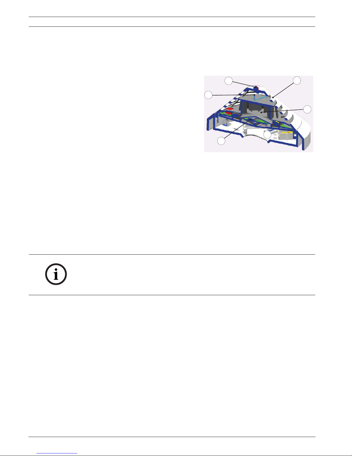
An LED sends light into the measuring chamber (see Figure 2.1, item 1), where it is absorbed
by the labyrinth structure. In the event of a fire, smoke enters the measuring chamber. The
light is scattered by the smoke particles and hits the photo diodes, which transform the
quantity of light into a proportional electrical signal.
The DO detectors have a dual optical sensor that uses the different infrared and blue light
wavelengths (Dual Ray technology). This allows fires to be detected early and even the
smallest quantities of smoke (TF1) to be reliably detected.
2.2.2 Thermal Sensor (Heat Detector)
A thermistor (see Figure 2.1, item 2) in a resistance network is used as a thermal sensor; an
analog-digital converter measures the temperature-dependent voltage at regular intervals.
Depending on the specified detector class, the thermal sensor triggers the alarm status when
the maximum temperature of 54 °C or 69 °C is exceeded (thermal maximum), or if the
temperature rises by a defined amount within a specified time (thermal differential).
1 Smoke measurement chamber with
optical sensor
Figure 2.1 Detector Configuration
2 Thermal sensor
3 Chemical sensor (covered on the cross-
section)
4 Individual display
5 PC board with evaluation electronics
6 MS 400 / MS 400 B Detector Base
6
4
5
2
1
3
NOTICE! The FAP-DO420 smoke detector makes an alarm decision based on an intelligent
combination of the following criteria:
– Amount of smoke density measured
– Speed of of smoke density increase
– Size of smoke particles (as measured by Dual Ray Technology)

Automatic Fire Detectors LSN improved
version
System Overview | en 7
Bosch Sicherheitssysteme GmbH Operation Guide F.01U.003.448 | 8.0 | 2011.10
2.2.3 Chemical Sensor (Gas Sensor)
2.3 System Description
Up to three detection principles are integrated in FAP-420/FAH-420 series detectors:
– Optical (for smoke): O
– Dual-optical (for smoke): DO
– Thermal (for heat): T
– Chemical (for gas): C
The individual sensors are programmed via the LSN network manually or using a timer. All
sensor signals are analyzed continually by the internal signal analysis electronics (ISP) and are
linked with each other. By linking the sensors (combined detectors), the detector can also be
used in places where the work carried out gives rise to light smoke, steam or dust. If a signal
combination fits the selected identifier for the area of operation for the detectors, an alarm is
triggered automatically.
2.4 Flash Frequency and Error Detection
The LSN improved detector has two centrally positioned two-color LEDs that flash green to
display the operational status.
The green LED on LSN improved FAP-420/FAH-420 series detectors is deactivated when
delivered. It can be activated as required via the programming software.
The LSN improved detector permanently monitors and adjusts itself throughout its life cycle
in order to adapt its sensitivity to the set threshold value.
A message is sent to the fire panel if the detector becomes too contaminated.
The LED will start to flash red as soon as an alarm is triggered.
The detector will return to its normal operating condition when the alarm is canceled via the
control panel or if the alarm cause disappears.
2.5 Features
– Active self-monitoring of the sensors, with display on the fire panel:
– Active adjustment of the threshold (drift compensation) if the optical sensor
becomes contaminated.
– Active adjustment of the threshold (drift compensation) of the chemical sensor.
– EMC safety is 50 V/m in the 1-3000 MHz range and is therefore much higher than
required by VdS 2110 (VdS Schadenverhütung GmbH).
– Preservation of LSN loop functions in the event of wire break or short-circuit of a
detector through integrated isolators.
– Individual detector identification on the fire panel in the event of an alarm. Alarm
indication on the detector with a flashing red LED.
– Programmable, i.e. can be adjusted to the area of operation.
The gas sensor (see Figure 2.1, item 3) detects mainly the
carbon monoxide (CO) that is produced by a fire, but it also
detects hydrogen (H) and nitrogen monoxide (NO).
The underlying measurement principle is CO oxidation and
the measurable current that it creates. The sensor signal
value is proportional to the concentration of gas.
The gas sensor supplies additional information in order to
reliably suppress disturbance variables.
Figure 2.2 Chemical sensor
3

8 en | System Overview
Automatic Fire Detectors LSN improved
version
F.01U.003.448 | 8.0 | 2011.10 Operation Guide Bosch Sicherheitssysteme GmbH
– Increased detection and false alarm security thanks to evaluation of the temporal
behavior of fire and disturbance variables.
– Activation of a remote indicator is possible.
– Optional mechanical removal safeguard (can be activated/deactivated).
– Dust-resistant labyrinth and cap construction.
– Every detector base has a Chamber Maid Plug (a cleaning opening with a plug) for
blowing out the optical chamber with compressed air (not required for the FAH-T 420
Heat Detector).
– For connecting to the FPA-5000 and FPA-1200 fire panels with extended range of LSN
features.
– You can only use DO detectors with the MPC-xxxx-B Panel Controller or the FPA-1200.
The MPC-xxxx-A Panel Controller cannot be used.
– In classic mode, can be connected to the BZ 500 LSN, UEZ 2000 LSN and UGM 2020 LSN
fire panels and to other panels or their receiver modules with identical connection
properties but with the existing LSN system limits. (Not DO detectors.)
– It is possible to read out the serial number, contamination level (for the O sensor),
operating hours and current analog values for each configured detector (except for KKW
types) via LSN.
– The DO detectors are not supported by the WinPara software.
– Use of shielded and unshielded cables.
– The LSN improved version line technology supports the connection of up to 254
FAP-420/FAH-420 series detectors per loop or stub (please observe national regulations
in this regard).
– Flexible network structures without additional elements ("T-Tapping") are possible.
– Automatic or manual detector addressing selectable.
– Compliant with EN 54, EN 50131 and VdS guidelines.

Automatic Fire Detectors LSN improved
version
Planning | en 9
Bosch Sicherheitssysteme GmbH Operation Guide F.01U.003.448 | 8.0 | 2011.10
3 Planning
3.1 Basic Installation/Configuration Notes
– Multi-sensor fire detectors must be planned in line with the guidelines for optical
detectors until a guideline for their planning is developed in collaboration with the VdS
(see also DIN VDE 0833 Part 2 and VDS 2095):
– Maximum monitoring area 120 m
2.
– Maximum installation height 16 m.
– If occasional switch-off of the optical sensor is required, the planning must occur
according to the guidelines for heat detectors (see DIN VDE 0833 Part 2 and VDS 2095):
– Maximum monitoring area 40 m
2.
– Maximum installation height 7.5 m.
– Maximum permissible air speed: 20 m/s.
– FAH-T 420 detectors must be configured according to Class A1R when planning fire
barriers conforming to DIBt.
3.2 Use in a Local Security Network (LSN/LSN improved version)
In a Local Security Network, the detectors connected to a fire panel can be operated in the
following operating modes:
3.3 Use in Areas with Elevated Radioactivity
There are two detector types available especially for use in areas with elevated radioactivity,
such as in nuclear power plants:
– FAP-O 420-KKW
– FAH-T 420-KKW
NOTICE!
FAP-420/FAH-420 Automatic Fire Detectors are not designed for exterior use.
Detector Type Operating mode
Combined Optical Thermal
maximum
Thermal
differential
FAP-OTC420XXXX
FAP-OT 420 X X X X
FAP-O 420/
FAP-O 420 KKW
-X- -
FAH-T 420/
FAH-T 420 KKW
--XX
FAP-DO420 - X - -
FAP-DOT420 X X X X
FAP-DOTC420 X X X X
NOTICE!
Planning should take the anticipated total current and line resistance into account to ensure
each detector has an operating voltage of at least 15 V DC.

10 en | Programming
Automatic Fire Detectors LSN improved
version
F.01U.003.448 | 8.0 | 2011.10 Operation Guide Bosch Sicherheitssysteme GmbH
4 Programming
Programming occurs via a PC or laptop connected to the fire panel
– With FSP-5000-RPS (Remote Programming System) for panels with LSN improved
version line technology
– With WinPara for panels with conventional LSN line technology (not DO-Melder).
420 series detectors are programmed by entering the area of operation. The selection of the
area of operation determines the optimum characteristic field for fire and disturbance
variable evaluation.
When optical sensor sensitivity in the FAP-OTC 420 and FAP-DOTC420 is low, the detector
only triggers if both smoke and an increase in CO concentration or temperature is detected.
The operating mode can be changed for the FAP-OTC 420 and FAP-OT 420 detector models,
as well as the FAP-DOTC420 and FAP-DOT420 models, i.e. individual sensors can be switched
off:
– Switch to optical (O sensor sensitivity = low, T sensor = switched off)
– Switch to thermal differential (T sensor sensitivity = A2R, O sensor = switched off)
– Switch to thermal maximum (T sensor sensitivity = A2S, O sensor = switched off).
In the case of the purely optical FAP-O 420 and FAP-DO420 detectors, the sensitivity of the
optical sensor can be set to three levels. Depending on the operating location, the optical
sensor in the detector is thus adjusted to the environmental conditions.
The FAH-T 420 Heat Detector is programmed by taking into account the ambient temperature,
the installation height and the sensitivity class selection.
Programming of the optical, thermal, and chemical sensors and the linking of all sensors via
algorithms significantly increases the detection ability and security against false alarms.
4.1 FAP-DOTC420 / FAP-OTC 420
NOTICE!
For fire detection, the purely optical detector also evaluates the time behavior of the fire
characteristics, which differs significantly from the time behavior of disturbance variables and
that occurring during a detector test
As a result, there are also different trigger times when testing with a test aerosol outside of
Walk test operation (10 s to max 60 s), depending on the selected sensitivity adjustment.
NOTICE! The default setting of the FAP-DOTC 420 and FAP-OTC 420 detector types in RPS
and WinPara is "Office (smoker) / Waiting Room / Restaurant /Meeting Room". For a
description of this setting, see the below table.

Automatic Fire Detectors LSN improved
version
Programming | en 11
Bosch Sicherheitssysteme GmbH Operation Guide F.01U.003.448 | 8.0 | 2011.10
Selectable installation locations in
the programming software (WinPara
and FSP-5000-RPS)
Detector Type Sensitivity
Thermom
ax (T
max
)
Optical
(O)
Chemical
(C)
Office (after hours) O, T
max
, T
diff
, C High (A2) High High
Office (smoker)/waiting room/
restaurant/meeting room
= default setting
O, T
max
, T
diff
, C High (A2) Low* Low
Office (day mode) O, T
max
, T
diff
, C Low (B) Medium High
EDP room O, T
max
, T
diff
, C High (A2) High High
Production location O, T
max
, T
diff
, C Low (B) Low* Medium
Garage O, T
max
, T
diff
, C High (A2) Low* Low
High storage warehouse without
vehicle traffic with combustion
engine
O, T
max
, T
diff
, C Low (B) High High
Conference hall/waiting room/
fairground
O, T
max
, T
diff
, C High (A2) Low* Medium
Kitchen/casino/restaurant during
active operation
O, T
max
, C Low (B) Low* Low
Warehouse with vehicle traffic O, T
max
, T
diff
, C Low (B) Low* Low
Rate of rise only (optical sensor off)** T
max
, T
diff
High (A2) - -
Optical only (thermal sensor off)**,
***
O-Low-
Fixed temperature heat only (optical
sensor off)**
T
max
High (A2) - -
Optical/chemical (thermal sensor
off)**, ***
O, C - Low High
Schools/kindergarten O, T
max
, T
diff
, C High (A2) Medium High
Theater/concert hall O, T
max
, T
diff
, C High (A2) Medium High
O = optical sensor (dual-optical in FAP-DOTC420 detectors)
T
max
= thermal maximum unit
T
diff
= thermal differential unit
C = chemical sensor
* If optical sensor sensitivity is low, the detector will only trigger if smoke as well as an
increase in CO concentration or temperature is detected.
** FSP-5000-RPS only
*** For FAP-DOTC420: does not comply with EN54-7
For details on installation height, see Section 4.4 FAH-T 420/FAH-T 420-KKW, page 13
NOTICE!
The FAP-DOTC420 detector is not supported by the WinPara programming software.

12 en | Programming
Automatic Fire Detectors LSN improved
version
F.01U.003.448 | 8.0 | 2011.10 Operation Guide Bosch Sicherheitssysteme GmbH
4.2 FAP-DOT420 / FAP-OT 420
4.3 FAP-DO420 / FAP-O 420 / FAP-O 420-KKW
NOTICE! The default setting of the FAP-DOT 420 and FAP-OT 420 detector types in RPS and
WinPara is "Office (day mode)". For a description of this setting, see the below table.
Selectable installation locations in the
programming software (WinPara and
FSP-5000-RPS)
Detector Type Sensitivity
Thermomax
(T
max
)
Optical
(O)
Office (after hours) O, T
max
, T
diff
High (A2) High
Office (smoker)/waiting room/restaurant/
meeting room
O, T
max
, T
diff
High (A2) Low
Office (day mode)
= default setting
O, T
max
, T
diff
Low (B) Medium
EDP room O, T
max
, T
diff
High (A2) High
Production location O, T
max
, T
diff
Low (B) Low
Garage
– FAP-OT 420
– FAP-DOT420
T
max
, T
diff
T
max
, T
diff
High (A2)
High (A2)
-
Low
High storage warehouse without vehicle traffic
with combustion engine
O, T
max
, T
diff
Low (B) High
Conference hall/waiting room/fairground O, T
max
, T
diff
High (A2) Low
Kitchen/casino/restaurant during active operation T
max
Low (B) -
Warehouse with vehicle traffic O, T
max
, T
diff
Low (B) Low
Rate of rise only (optical sensor off)** T
max
, T
diff
High (A2) -
Optical only (thermal sensor off)** O - Low
Fixed temperature heat only (optical sensor off)** T
max
High (A2) -
Schools/kindergarten O, T
max
, T
diff
High (A2) Medium
Theatre/concert hall O, T
max
, T
diff
High (A2) Medium
O = optical sensor (dual-optical in FAP-DOT420 detectors)
T
max
= thermal maximum unit
T
diff
= thermal differential unit
** FSP-5000-RPS only
For details on installation height, see Section 4.4 FAH-T 420/FAH-T 420-KKW, page 13
NOTICE!
The FAP-DOT420 detector is not supported by the WinPara programming software.
NOTICE! The default setting of the FAP-DO 420 and FAP-O 420 detector types in RPS and
WinPara is "Medium". For a list of possible installation locations and corresponding sensitivity
settings, see the below table.

Automatic Fire Detectors LSN improved
version
Programming | en 13
Bosch Sicherheitssysteme GmbH Operation Guide F.01U.003.448 | 8.0 | 2011.10
4.4 FAH-T 420/FAH-T 420-KKW
Sensitivity classes as per EN 54 Part 5
With the detector types FAH-T 420 and FAH-T 420-KKW, it is possible to set one of the
sensitivity classes listed above in line with planning.
In the sensitivity classes A1, A2S and BS, the FAH-T 420 or FAH-T 420-KKW is operated purely
as a thermal maximum detector. In this case, the detector does not activate at below 54 °C in
class A2S, and not below 69 °C in class BS.
The sensitivity classes A2S and BS are therefore particularly suitable for applications where
higher temperature rates-of-rise occur over a longer period, e.g. in kitchens or boiler rooms.
The sensitivity classes A1R, A2R and BR indicate that the thermal differential unit is active in
addition to the thermal maximum unit.
These sensitivity classes are especially well-suited for use in unheated buildings where the
ambient temperature can vary greatly but high temperature rates-of-rise do not last long.
The thermal differential unit enables class A1R/A2R detectors to respond at T<54 °C and class
BR detectors at T<69 °C.
The selection of the sensitivity class also depends on the installation height of the detector.
To maintain the greatest possible security against false alarms, classes A1 and A1R should not
be selected for room heights below 6 m, although these classes are in theory permitted.
Furthermore, the expected application temperature must be taken into consideration.
Installation locations Selectable sensitivity
Theater/concert hall Medium
Warehouse with vehicle traffic Low
Office (smoker)/waiting room/restaurant/meeting room Low
Conference hall/waiting room/fairground Low
Office (after hours) High
School/kindergarten Medium
Production location Low
EDP room High
High storage warehouse without vehicle traffic with combustion
engine
High
Office (day mode) Medium
Selectable installation locations in the programming software (WinPara and
FSP-5000-RPS)
§ A2R Typical application temperature: 25 °C, T
max
+ T
diff
, height up to 6 m
A2S Typical application temperature: 25 °C, only T
max
, height up to 6 m
A1R Typical application temperature: 25 °C, T
max
+ T
diff
, height 6 m to 7.5 m
A1 Typical application temperature: 25 °C, only T
max
, height 6 m to 7.5 m
BR Typical application temperature: 40 °C, T
max
+ T
diff
, height up to 6 m
BS Typical application temperature: 40 °C, only T
max
, height up to 6 m
§ = Basic setting in the WinPara and FSP-5000-RPS programming software

14 en | Programming
Automatic Fire Detectors LSN improved
version
F.01U.003.448 | 8.0 | 2011.10 Operation Guide Bosch Sicherheitssysteme GmbH
Temperature
rate-of-rise [K
min
-1
]
Response time for detectors in the
sensitivity class A1R
Response time for detectors in the
sensitivity classes A2R/BR
Lower limiting
value [min/sec]
Upper limiting
value [min/sec]
Lower limiting
value [min/sec]
Upper limiting
value [min/sec]
10 1min 4min 20s 2min 5min 30s
20 30 s 2 min 20 s 1 min 3 min 13 s
30 20 s 1 min 40 s 40 s 2 min 25 s
 Loading...