


DiBos

Operating Manual
DiBos/DiBos Micro

2 Operating Manual DiBos
Table of Contents
F.01U.512.560 A1/2005-09 Bosch Security Systems
Table of Contents
STARTING THE PROGRAM / LOGGING ON TO THE SYSTEM.....................................................................3
STARTING THE PROGRAM ......................................................................................................................................3
LOG ON TO THE SYSTEM........................................................................................................................................3
THE USER INTERFACE....................................................................................................................................4
THE SCREEN LAYOUT WHEN THE SYSTEM STARTS ...................................................................................................4
LIVE MODE........................................................................................................................................................5
THE USER INTERFACE IN LIVE MODE .......................................................................................................................5
THE MENU BAR IN LIVE MODE .................................................................................................................................6
THE DISPLAY BAR..................................................................................................................................................7
THE DEVICE LIST IN LIVE MODE...............................................................................................................................8
THE CONTROL AND STATUS FIELD...........................................................................................................................9
THE IMAGE AREA IN LIVE MODE.............................................................................................................................15
THE IMAGE WINDOW............................................................................................................................................17
THE EVENT FIELD ................................................................................................................................................18
PLAYBACK MODE..........................................................................................................................................20
THE USER INTERFACE IN PLAYBACK MODE ............................................................................................................20
THE MENU BAR IN PLAYBACK MODE ......................................................................................................................21
THE DISPLAY BAR................................................................................................................................................23
THE DEVICE LIST IN PLAYBACK MODE....................................................................................................................24
THE IMAGE AREA IN PLAYBACK MODE....................................................................................................................25
THE IMAGE WINDOW............................................................................................................................................27
THE TIMELINE AREA.............................................................................................................................................28
OPERATING PROCEDURES - LIVE / PLAYBACK MODE............................................................................34
DISPLAY INCOMING ALARMS.................................................................................................................................34
CREATING/EDITING FAVORITES ............................................................................................................................35
DISPLAY LOGBOOK..............................................................................................................................................37
START/EXIT CAMERA ROUND................................................................................................................................38
LOG OFF / CHANGE USER.....................................................................................................................................38
OPERATING PROCEDURES - LIVE MODE...................................................................................................39
FILTER EVENT LIST ..............................................................................................................................................39
ZOOM / CONTROL DOME CAMERAS AND PAN/TILT CAMERAS....................................................................................40
OPERATING PROCEDURES - PLAYBACK MODE.......................................................................................42
SEARCH FOR MOTION ..........................................................................................................................................42
SEARCH FOR ADDITIONAL DATA............................................................................................................................43
EXPORTING FILES................................................................................................................................................44
IMPORT EXPORTED FILES.....................................................................................................................................45
AUTHENTICATE IMAGES FROM SEVERAL CAMERAS.................................................................................................46
AUTHENTICATE A SINGLE IMAGE...........................................................................................................................46
PROTECT VIDEO..................................................................................................................................................47
DELETE VIDEO ....................................................................................................................................................47
THE ICON LIST................................................................................................................................................48
LIST OF ICONS.....................................................................................................................................................48

DiBos Operating Manual 3
Starting the program / logging on to the system
Bosch Security Systems A1/2005-09 F.01U.512.560
Starting the program / logging on to the system
Starting the program
When installation is complete, you can start the program.
1. Switch on the computer and wait until the desktop appears.
2. Double-click on the DiBos icon on your desktop or select "Start - All Programs - DiBos". The program
is started and the log-on dialog box appears.
Log on to the system
After the program has started, the dialog box for logging on to the system appears.
1. Type the logon ID in the Name input box.
2. Type the password in the Password input box.
3. Click "OK". You are now in live mode.
Note: In systems which are linked to an LDAP server, an additional selection field appears beneath the
password. Here you must select whether you want to log on locally or onto the LDAP server.
4 Operating Manual DiBos
The user interface
F.01U.512.560 A1/2005-09 Bosch Security Systems
The user interface
The screen layout when the system starts
You will automatically access live mode every time the system is re-started and every time you log on. You
can look at live images from selected cameras in this mode.
It is possible to switch quickly into playback mode and back by clicking on the button. The button you select
is then color-highlighted.
Live mode
Playback mode
Button for live mode
Button for playback mode

DiBos Operating Manual 5
Live mode
Bosch Security Systems A1/2005-09 F.01U.512.560
Live mode
The user interface in live mode
The user interface is divided into different areas.
1
Menu bar with current date and time
2
Display bar
3
Device list with camera and remote stations
4
Image area with image window
5
Control and status field
6
Event field

6 Operating Manual DiBos
Live mode
F.01U.512.560 A1/2005-09 Bosch Security Systems
The menu bar in live mode
The menu bar has the following functions.
System
Configuration wizard Helps you to create a basic system configuration quickly.
Configuration Displays the configuration.
Database information Displays information on the cameras, e.g. free memory, average image size
etc.
Logbook Displays specific events for local systems or a remote station.
Log off / change user Logs the user off the system. The system continues running in the background.
A different user can log on.
Change password You can enter a new password.
Exit Exits the program (administrator rights necessary).
Selected image
window
Save image Saves the image displayed in the selected image window. It can be saved as
an HTML, BMP, JPG, GIF, TIF or PNG file. If it is saved as a HTML file, the
additional data is also saved.
Print image Prints the image displayed in the selected image window (including the
additional data and a commentary).
Motion data Shows the areas where a motion was detected in the selected image window.
To hide it, repeat the command.
Note: The search for motion function is only possible with locally connected
cameras.
View
Large icons Displays the icons in the device list in large format. To minimize them, repeat
the command.
Large image area Enlarges the image area and minimizes the event field. To minimize the image
area, select the command again.
Large device list Enlarges the device list and minimizes the control and status fields. To
minimize the device list, select the command again.
?
Help Displays online help
Info Displays system information.
DiBos Operating Manual 7
Live mode
Bosch Security Systems A1/2005-09 F.01U.512.560
The display bar
The display bar contains the following buttons:
Buttons for live and playback mode
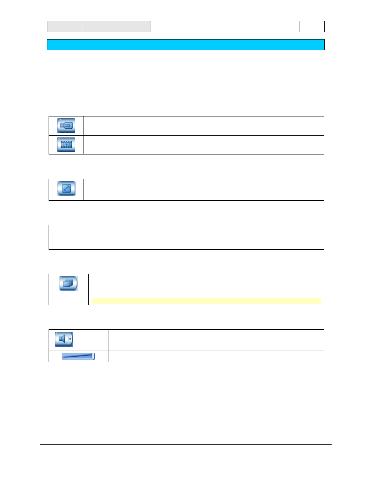
Button for live mode
Button for playback mode
Button for full image
Clicking on the button enlarges the image area to create a full image.
Press the ESC button to switch to the original image display.
Buttons for arranging the image display in the image area
The buttons show how many image windows are shown
in the image area when this button is selected. Every
single image window shows the live image of a camera.
Button for camera round
A dialog box opens after the button is clicked. Enter the length of time after which the
system switches over from one camera to the other. During the camera round, all
cameras selected in the image area are displayed one after the other.
Note: Clicking on the button again ends the camera round.
Switching sound button on and off
Clicking on the button switches the sound on or off.
To adjust the volume, click on the down arrow .
Select the volume you require with the volume regulator.
8 Operating Manual DiBos
Live mode
F.01U.512.560 A1/2005-09 Bosch Security Systems
The device list in live mode
The device list is located on the left-hand side of the screen. Depending on what is selected, the following
are displayed:
• configured remote stations or cameras.
• Favorites view.
• incoming alarms.
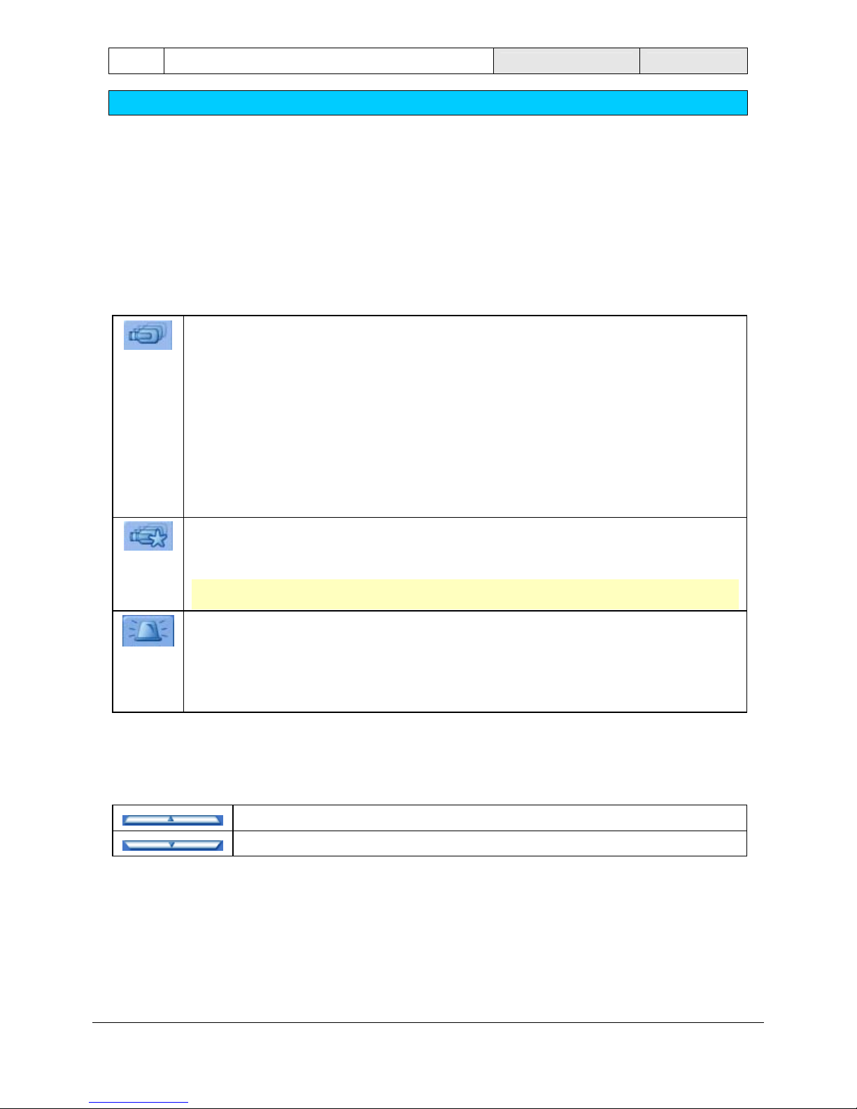
Configured cameras and/or remote stations
All locally-connected cameras are listed.
If remote stations have been configured, they are listed along with the cameras connected to
them.
Network remote stations are automatically connected to the local system. Right-clicking on
the remote station icon and selecting the "Disconnect" command disconnects the remote
station.
RAS remote stations must be connected manually. To do so, right-click on the remote station
and select the "Connect" command.
The status of the devices is shown by the icons.
Favorites view
Favorites which have been saved are listed and can be called up by double-clicking on the
icon. New favorites can be created.
Note: A favorite is understood to mean a number of cameras which are displayed in a
specific way, e.g. camera 1 to 4 in the 2 x 2-image window view.
Incoming alarms
The icon flashes red after alarms have been received in the system.
Click on the icon and the flashing stops and the cameras in alarm status are listed. Double-
clicking on the camera icon shows the camera image in the selected window of the image
area. The image can be displayed in any window at all using the "Drag and drop" function.
Enlarging and minimizing device list
Click on the bar between the device list and the control and status field.
Minimizes the device list
Enlarges the device list
DiBos Operating Manual 9
Live mode
Bosch Security Systems A1/2005-09 F.01U.512.560
The control and status field
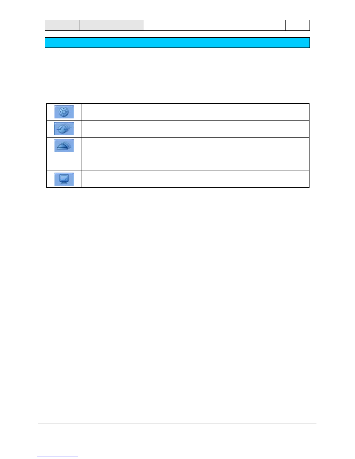
You have the following options in the control and status field. Select the tab of the function you require. Use
the tabs' arrows to display hidden icons.
The control field for dome cameras and pan/tilt cameras is displayed.
The relays which have been configured are displayed.
The alarm inputs which have been configured are displayed.
Instant playback is started.
The monitors' control field is displayed.
10 Operating Manual DiBos
Live mode
F.01U.512.560 A1/2005-09 Bosch Security Systems
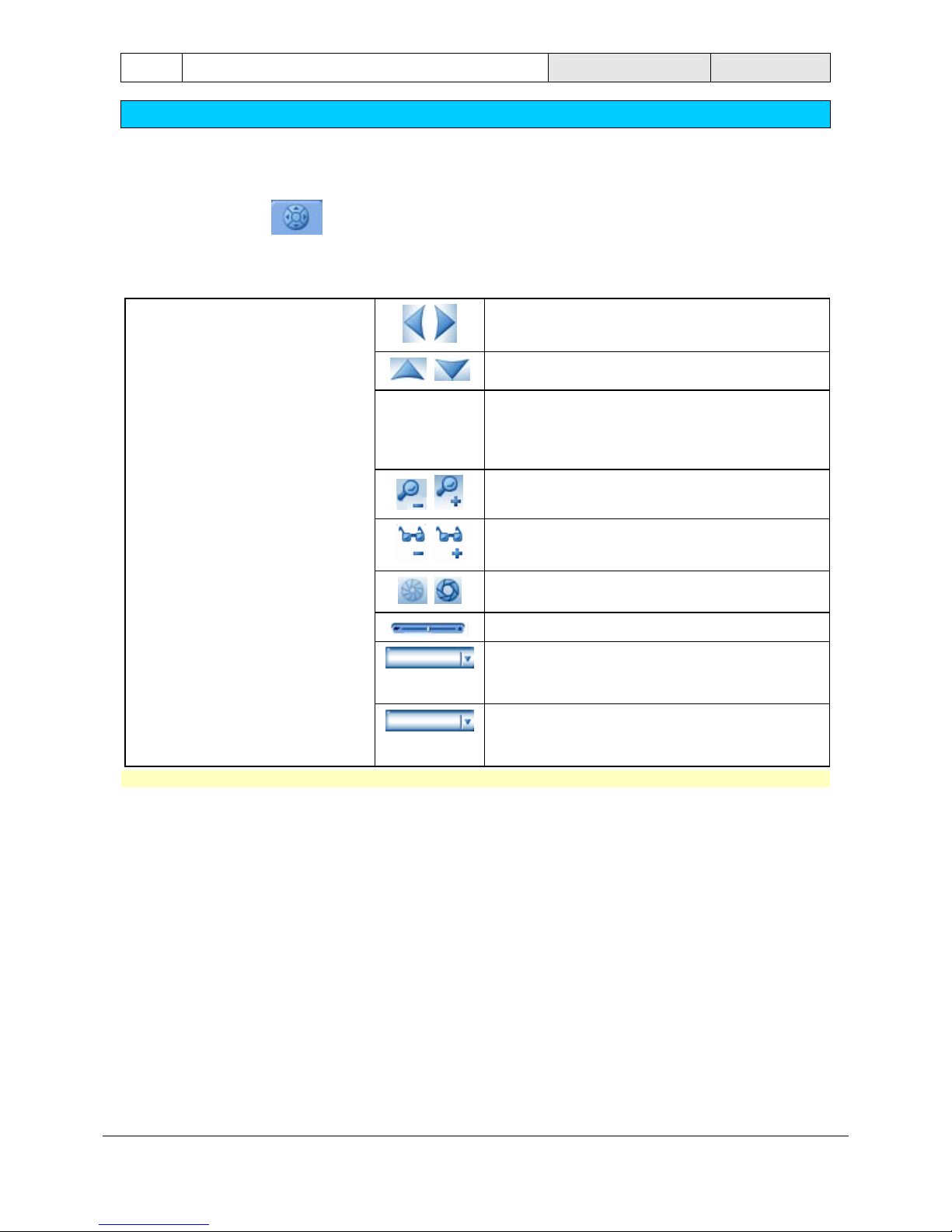
Control field for dome cameras and pan/tilt cameras
After selecting this tab , the control field for dome cameras and pan/tilt camera s is displayed. The
control field does not become active until a dome camera or pan/tilt camera is displayed in the selected
image window. When you move the mouse cursor over the various elements, they are highlighted optically.
If no dome camera or pan/tilt camera has been selected, the control field is inactive.
Pan the camera to the left/right.
Pan the camera up/down.
Pans the camera in all directions. To do so, move
the mouse cursor on to the icon, press and hold
the left mouse button, and drag the icon in the
direction that you want to pan the camera in.
Enlarge picture angle (zoom angle) / minimize
picture angle (wide angle)
Focus near / focus far (set the image so it is in
focus)
Close iris/ open iris
Sets the pan speed
(on left)
Camera positions which have been set can be
called up. To do so, click on the down arrow and
make your selection.
(on right)
Camera commands which have been saved can
be called up. To do so, click on the down arrow
and make your selection.
Note: It is also possible to control these functions in the image window.
DiBos Operating Manual 11
Live mode
Bosch Security Systems A1/2005-09 F.01U.512.560
Display of relay
After selecting the tab, all locally configured relays and their statuses are displayed.
If remote stations have been configured, a selection field appears in the lower area. Click on the down arrow ,
and select the remote station in order to list the relays connected to it.
The relays can be activated or deactivated as follows:
• Double-click with the left mouse button on the relay icon
or
• Right click and select the "Activate/deactivate" command
The relay is inactive.
The relay is active.
12 Operating Manual DiBos
Live mode
F.01U.512.560 A1/2005-09 Bosch Security Systems
Display alarm inputs
After selecting the tab, all locally configured alarm inputs and their statuses are displ ayed.
If remote stations have been configured, a selection field appears. Click on the down arrow , and select the
remote station in order to list the alarm inputs connected to it.
Alarm input on standby.
Alarm input has triggered.
Note: alarm simulation inputs can be activated/deactivated by double-clicking or right clicking.
DiBos Operating Manual 13
Live mode
Bosch Security Systems A1/2005-09 F.01U.512.560
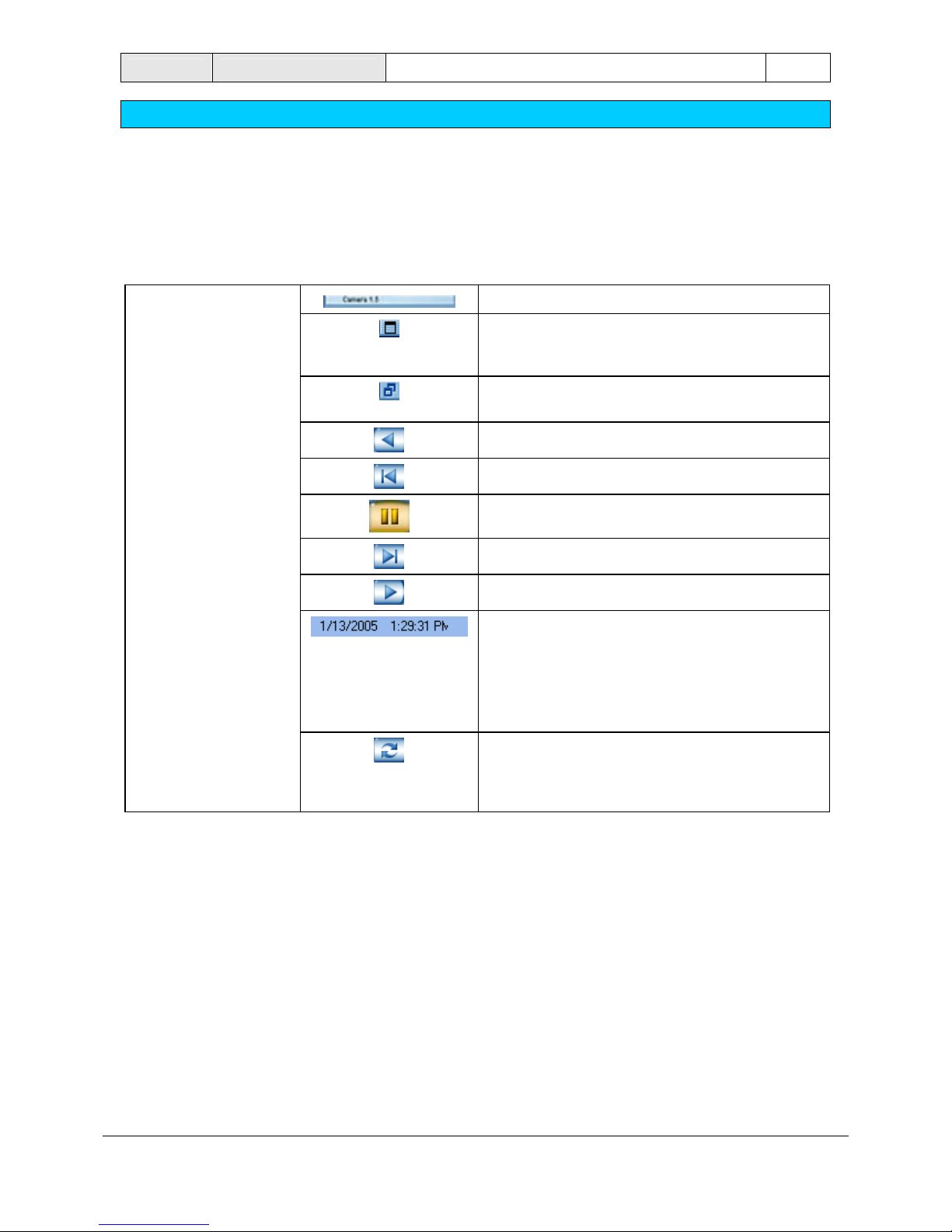
Start instant playback
After selecting the tab, the images which have bee n saved in the selected camera are played back
instantly as live images. This means you will see the live image of the camera and the image of this camera
from about 30 seconds ago. Playback is in real time. The time delay can be set in the configuration.
Name of the camera
Enlarges the image. The image is displayed in a
window which can be moved and whose size can
be changed.
Minimizes the image (icon is located in the top
right-hand corner of the enlarged image).
Play reverse (real time)
Single image backwards
Pause
Single image forward
Play forward (real time)
Time at which the playback occurs
You can start the playback at any time at all. Just
click on day, month, year, hour, minute or second
and enter the time you want. Confirm the entries
with "Enter".
The image taken at this time will be displayed.
Playback starts at the configured time. The value
which has been set in the configuration is used,
i.e. there is a 30-second time delay between
playback and the live image.
14 Operating Manual DiBos
Live mode
F.01U.512.560 A1/2005-09 Bosch Security Systems
Control field for monitors
After selecting the tab, 2 monitors are displayed in the control field. Only locall y connected cameras
can be displayed on the monitors.
Monitors A and B
Starts the sequence, i.e. the cameras which have been
assigned to the monitor in the configuration are displayed one
after the other.
You return to the "Default view", i.e. the configured camera is
displayed on the monitor.
A camera or sequence can be assigned to a monitor.
Assign using "Drag and Drop"
Only one camera can be assigned to a monitor with "Drag and Drop". This procedure can be repeated as
often as necessary. When a new user logs on, the camera which has been assigned with "Drag and Drop" is
replaced by the camera assigned in the configuration.
• Press and hold the left mouse button, drag a camera from the camera list onto the monitor in the
control field.
or
• Place the mouse cursor in the title bar of an image window, press and hold the left mouse button and
drag the camera onto the monitor.
Assign in the configuration
In the configuration ("Video and audio connections" menu), specify which camera is to be displayed by
default on which monitor, and which cameras are to be played as a sequence.
Note: The configuration specifies which cameras are to be visible for whi ch u se rs ("Authorization levels"
menu).
Enlarge and minimize control and status field
Click on the bar above the control and status field.
Enlarges the control and status field.
Minimizes the control and status field.
DiBos Operating Manual 15
Live mode
Bosch Security Systems A1/2005-09 F.01U.512.560
The image area in live mode
The middle and right-hand side of the screen is where live images or images which have been saved are
displayed.
Arrange this area to suit your requirements. Proceed as follows:
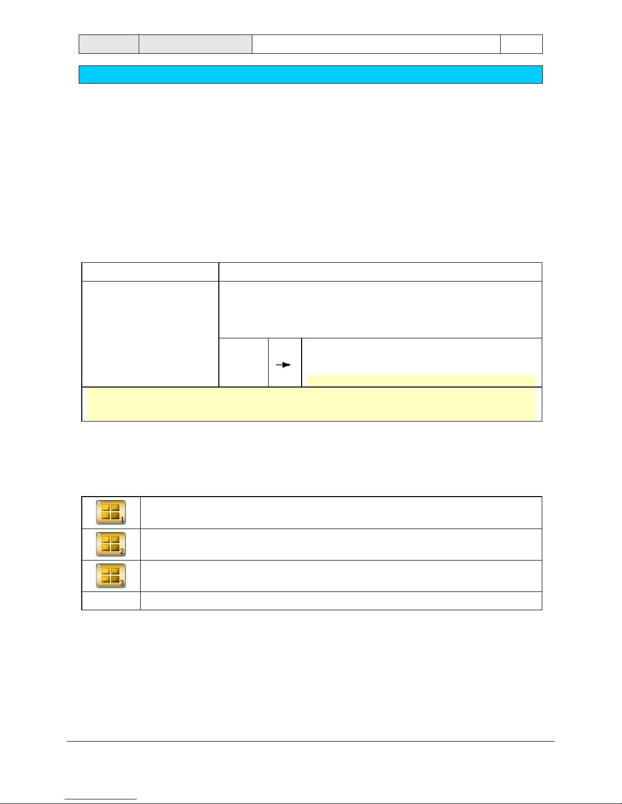
Specify the number and layout of image windows in the image area
Here you can specify what the image area looks like, i . e. the number and layout of the image windows. The
buttons are located in the display bar above the image area.
You can choose between 5 buttons with symmetrical and one button with asymmetrical image display.
Symmetrical image windows Asymmetrical image wi ndows
You can display one or more larger image windows surrounded by
smaller image windows.
To do so, click on the down arrow beside the button on the right, and
select a display.
View with 1 image, 4
images, 9 images, 16
images or 30 images.
Note: The last view used is copied to the display bar.
Note: At least 1 image window is selected in every display selected by you. The display you select
appears with a yellow border. The image of the camera on which you double-click in the device list is
shown in this image window.
The number to the right beneath the button shows the user how often he has already clicked on this button.
This number also indicates which cameras have been selected or which cameras will be selected the next
time the user clicks this button.
Example: With 16 cameras and 2x 2 image windows this means:
You can click on the button four times so that all cameras are displayed.
Cameras 1 to 4 are displayed (the number "1" appears on the right beneath the button).
Cameras 5 to 8 are displayed (the number "2" appears on the right beneath the button).
Cameras 9 to 12 are displayed (the number "3" appears on the right beneath the button)
etc.
16 Operating Manual DiBos
Live mode
F.01U.512.560 A1/2005-09 Bosch Security Systems
Place individual cameras in the image area
After selecting the image display, you will now want to display specific cameras.
You can do so as follows:
• Place by double-clicking
Double-clicking on a camera icon in the device list places the camera in the selected image windo w (with
the yellow border).
Left-click with the mouse to select a different image window. Double-clicking on a different camera i con
places its image in the new image window that you have selected.
• "Drag and Drop"
Press and hold the left mouse button and drag the camera icon from the device list into an image
window. Release the mouse button and the image of this camera appears in the image windo w.
Note: In the image area, each camera can only be displayed once.
Move cameras within the image area
In a multiple-image display, you can move cameras within the image areas.
To do so, move the mouse cursor into the title bar of an image window, press and hold the left mouse button
and drag the camera into a different image window. Release the mouse button and the image of this camera
appears in the image window.
Enlarge and minimize image area
Click on the bar beneath the image area.
Minimizes the image area.
Enlarges the image area.
 Loading...