


DHG6023RUC
Ventilation Blower Motor
0RGHOV
DHG6023RUC

Table of Contents
Safety . . . . . . . . . . . . . . . . . . . . . . . . . . . . . . . . . . . . 1
Installation . . . . . . . . . . . . . . . . . . . . . . . . . . . . . . . . 2
Step 1: EXHAUST-AIR MODE . . . . . . . . . . . . . . 2
Step 2: PREPARING THE WALL . . . . . . . . . . . . 2
Step 3: INSTALLATION . . . . . . . . . . . . . . . . . . . 3
Wire Diagram . . . . . . . . . . . . . . . . . . . . . . . . . . . 5
Safety Definitions
WARNING
This indicates that death or serious injuries may
occur as a result of non-observance of this warning.
CAUTION
This indicates that minor or moderate injuries may
occur as a result of non-observance of this warning.
Additional information on products, accessories,
replacement parts and services can be found at
www.bosch-home.com and in the online shop
www.bosch-home.com/us/store.
NOTICE: This indicates that damage to the appliance or
property may occur as a result of non-compliance with this
advisory.
Note: This alerts you to important information and/or tips.
This Bosch Appliance is made by
BSH Home Appliances Corporation
1901 Main Street, Suite 600
Irvine, CA 92614
Questions?
1-800-735-4328
www.bosch-home.com/us
We look forward to hearing from you!
Safety
IMPORTANT SAFETY INSTRUCTIONS
READ AND SAVE THESE INSTRUCTIONS
IMPORTANT: Save these Instructions for the Local Gas
Inspector’s use.
INSTALLER: Please leave these Installation Instructions
with this unit for the owner.
OWNER: Please retain these instructions for future
reference.This appliance conforms to the relevant safety
regulations.
Repairs should only be carried out by qualified specialists.
Check if this blower is recommended by the manufacturer
to be installed with the hood.
WARNING
To avoid electrical shock hazard, before installing,
switch power off at the service panel and lock the panel
to prevent the power from being switched on
accidentally.
WARNING
TO REDUCE THE RISK OF FIRE,
OR INJURY TO PER
FOLLOWING:
a) Installation work and electrical wiring must be done
by qualified person(s) in accordance with all
applicable codes and regulations, including firerelated construction.
b) Sufficient air is needed for proper combustion and
exhausting of gases through the flue (chimney) of
fuel burning equipment to prevent back drafting.
Follow the heating equipment manufacturers
guideline and safety standards such as those
published by the National Fire Protection
Association (NFPA), and the American Society for
Heating, Refrigeration and Air Conditioning
Engineers (ASHRAE), and the local code
authorities.
c) When cutting or drilling into wall or ceiling, do not
damage electrical wiring and other hidden utilities.
d) To properly exhaust air, be sure to duct air outside.
DO NOT vent exhaust air into spaces within walls,
ceilings, attics, crawl spaces, or garages.
SONS, OBSERVE THE
ELECTRIC SHOCK,
WARNING
To reduce the risk of fire or electric
this blower with any solid-state
WARNING
State of California Proposition 65 Warnings:
This product contains chemicals known to the State of
California to cause cancer, birth defects or other
reproductive harm.
WARNING
To reduce the risk of fire, use only metal ductwork.
shock, do not use
speed control device.
Grounding instructions
This appliance must be grounded. In the event of an
electrical short-circuit, grounding reduces the risk of electric
shock by providing an escape wire for the electric current.
WARNING
Improper grounding can result in a risk of electric shock.
Consult a qualified electrician if the grounding
instructions are not completely understood, or if doubt as
to whether the appliance is properly grounded.
None of the packing materials cause pollution to the
environment and all can be recycled for use again. Please
help to protect the environment and dispose of the
packaging in an environment-friendly manner.
Remove all tape and packaging before using the appliance.
Destroy or recycle the packaging after unpacking the
appliance.
Never allow children to play with packaging material.
CAUTION
FOR GENERAL VENTILATING USE ONLY. Do not use
to exhaust hazardous or explosive materials and vapors.
English 1

Installation
Step 1: EXHAUST-AIR MODE
Equipment Needed
䙚 Drill and Bit
䙚
Screwdriver
䙚
Rubber Mallet
Equipment Included
䙚
Anchors (4)
䙚
Screws (4)
䙚
Connector
Exhaust air should not be directed into a smoke or exhaust
flue that is currently used for other purposes, nor into a
shaft that is used for ventilating rooms in which stoves or
fireplaces are also located.
Exhaust air must be discharged in accordance with official
and statutory regulations only (e.g. national building
regulations).
Local authority regulations must be observed when
discharging air into smoke or exhaust flues that are not
otherwise in use.
If the air intake is inadequate, there is a risk of carbon
monoxide poisoning from combustion gases which are
drawn back into the room.
An air-intake/exhaust-air wall box by itself is no guarantee
that the limiting value will not be exceeded.
NOTE: When assessing the overall requirement, the
combined ventilation system for the entire household must
be taken into consideration. This rule does not apply to the
use of cooking appliances, such as hobs and ovens.
IMPORTANT SAFETY INSTRUCTIONS
• The blower must be attached at least 78¾'' (200 cm)
from the extractor hood.
• When attaching the outer wall blower, ensure that it
is accessible for maintenance and repairs.
• The plug-and-socket connections of the electric
cables must be located inside the building,
according to local codes.
• DO NOT reduce the 6'' (152 mm) diameter of the
ducting connected to the extractor hood.
Step 2: PREPARING THE
WALL
When the extractor hood is operated in exhaust-air mode
simultaneously with a different burner which also makes
use of the same chimney (such as gas, oil or coal-fired
heaters, continuous-flow heaters, hot-water boilers), care
must be taken to ensure that there is an adequate supply of
fresh air, which will be needed by the burner for
combustion.
Safe operation is possible provided that the underpressure
in the room where the burner is installed does not exceed 4
Pa (0.04 mbar).
This can be achieved if combustion air can flow through
non-lockable openings, e.g. in doors, windows and via the
air-intake/exhaust-air wall box or by other technical
measures, such as reciprocal interlocking, etc.
䙚㻌㻌 The wall must be flat and perpendicular.
䙚㻌㻌
Ensure that the wall is capable of providing a firm hold
for mounting screws and anchors.
Weight: 10.3 kg / 23 lbs
We reserve the right to construction changes within the
context of technical development.
Technical
Electrical Requirements: 120 V; 60 Hz, max. 4.2 A
Duct Size: 6" (152 mm)
Information
English 2
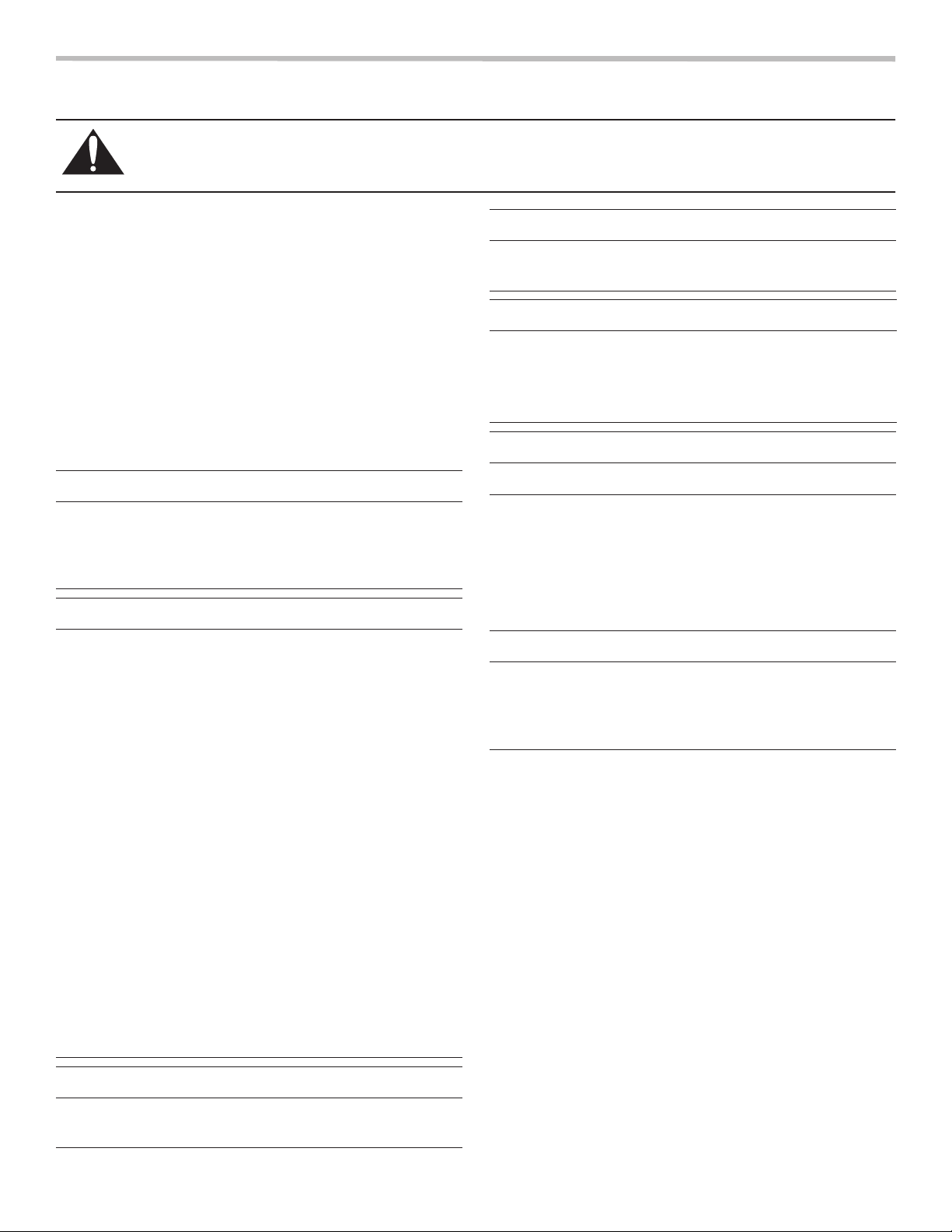
Step 3: INSTALLATION
min. 40"
(101.5 cm)
min. Ø ¾"
(19 mm)
½"
(12.7 mm)
(100 mm)
min. Ø 6½"
(16.5 mm)
15
/
16
"
3
(424 mm)
11
/
16
"
(211 mm)
5
/
16
"
8
(21 mm)
13
/
16
"
10⅞"
(276 mm)
5¼"
(133 mm)
1. Hold the blower on the wall.
Note the direction of the air conduction.
2. Mark the 4 mounting boreholes.
• At least one screw must be installed through a
stud.
• All hardware must be suitable for the wall’s
construction materials.
• Ensure the air outlet points downward.
3. Wall break:
Mark and drill a guide hole and a separate hole for
electrical conduit.
4. Drill the 4 x ¼'' (6,3 mm) Ø mounting boreholes.
Insert wall anchors and screw the blower to the wall.
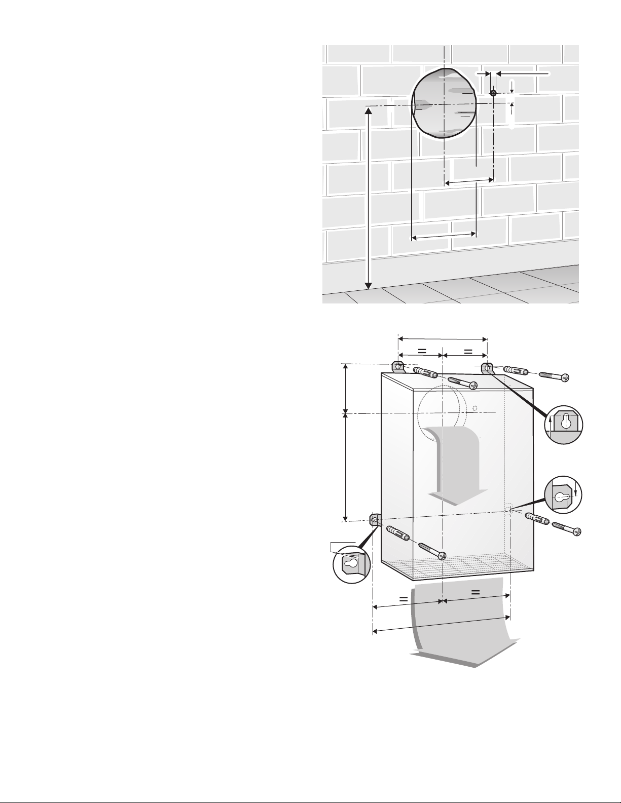
5. Connect the duct from the blower to the extractor hood
and feed to the outside.
min. 40"
min. 40"
(101.5 cm)
(101.5 cm)
15
15
3
(100 mm)
(100 mm)
min. Ø 6½"
min. Ø 6½"
(16.5 mm)
(16.5 mm)
10⅞"
10⅞"
(276 mm)
(276 mm)
/
/
16
16
min. Ø ¾"
min. Ø ¾"
"
"
(19 mm)
(19 mm)
(12.7 mm)
(12.7 mm)
½"
½"
5¼"
5¼"
(133 mm)
(133 mm)
5
5
8
/
/
16
16
(211 mm)
(211 mm)
13
13
"
"
/
/
16
16
(21 mm)
(21 mm)
"
"
11
11
"
"
161616
(424 mm)
(424 mm)
/
/
16
16
English 3
6. Connect the blower to the extractor hood with an
(21 mm)
13
/
16
"
extension cable if required.
Use the added connector to hard-wire to the blower, if
required.
Use the wire diagram for connecting.
WARNING
The additional cover on the plug must always be
•
attached and closed for safety reasons.
Not needed wires must be isolated, capped with wire
•
nuts and stored in a safe position.
13
13
"
"
/
/
16
16
(21 mm)
(21 mm)
NOTE: Confirm that the blower is securely attached to the
wall and all connections are secure.
NOTE: The unit can also be installed on the roof in
combination with a roof plate accessory (RFPLT600P or
RFPLT1000P). Ask your retailer or contact the Bosch
Customer Service Team at 1-800-944-2904.
English 4

Wire Diagram
speed 1 (red)
speed 2 (blue)
speed 3 (orange)
speed 4 (brown)
N (white)
PE (green/yellow)
orange
brown
green/yellow
blue
red
white (N)
English 5
 Loading...