


en Operating and installation instructions
fi Käyttöoja Asennusohje
da Brugsog montageveiledning
no Bruksog Monteringsanvisning
sv Bruksoch Monteringsanvisning

en
fi
da
page |
03 – 15 |
Sivu |
16 – 28 |
side |
29 – 41 |
no
sv
side |
42 – 54 |
sid |
55 – 67 |
Fig. 1 |
Abb. 1 |
GAS |
ELEKTRO |
GAZ |
ELECTR. |
KAASU |
ELETT. |
GASS |
EL. |
min. 650 |
min. 430 |
|
2

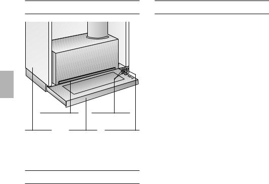
Instructions for use:
Appliance description
Wall |
Ventilator |
|
cupboard |
||
switches |
||
Filter frame |
||
|
Pull-out vapour |
Light switch |
extractor |
|
Operating modes
Exhaust-air mode:
The extractor-hood fan extracts the kitchen vapours and conveys them through the grease filter into the atmosphere.
The grease filter absorbs the solid particles in the kitchen vapours.
The kitchen is kept almost free of grease and odours.
DWhen the extractor hood is operated in exhaust-air mode simultaneously with a different burner which also makes use of the same chimney (such as gas, oil or coal-fired heaters, continuous-flow heaters, hot-water boilers) care must be taken to ensure that there is an adequate supply of fresh air which will be needed by the burner for combustion.
Safe operation is possible provided that the underpressure in the room where the burner is installed does not exceed 4 Pa (0.04 mbar).
Operating modes
This can be achieved if combustion air can flow through non-lockable openings, e.g. in doors, windows and via the air- intake/exhaust-air wall box or by other technical measures, such as reciprocal interlocking, etc.
If the air intake is inadequate, there is a risk of poisoning from combustion gases which are drawn back into the room.
An air-intake/exhaust-air wall box by itself is no guarantee that the limiting value will not be exceeded.
Note: When assessing the overall requirement, the combined ventilation system for the entire household must be taken into consideration. This rule does not apply to the use of cooking appliances, such as hobs and ovens.
Unrestricted operation is possible if the extractor hood is used in recirculating mode
– with activated carbon filter.
Circulating-air mode:
An activated carbon filter must be fitted for this operating mode (see Filters and
maintenance).
The complete installation set and replacement filters can be obtained from specialist outlets.
The corresponding accessory numbers can be found at the end of these operating instructions.
The extractor-hood fan extracts the kitchen vapours which are purified in the grease filter and activated carbon filter and then conveyed back into the kitchen.
The grease filter absorbs the grease particles in the kitchen vapours.
The activated carbon filter binds the odorous substances.
If no activated carbon filter is installed, it is not possible to bind the odorous substances in the cooking vapours.
3
Before using for the first time
Important notes:
The Instructions for Use apply to several versions of this appliance. Accordingly, you may find descriptions of individual features that do not apply to your specific appliance.
This extractor hood complies with all relevant safety regulations.
Repairs should be carried out by qualified technicians only.
Improper repairs may put the user at considerable risk.
Do not use the appliance if damaged.
The appliance is not intended for use by young children or infirmed persons without supervision.
Young children should be supervised to ensure they do not play with the appliance.
If the connecting cable for this appliance is damaged, the cable must be replaced by the manufacturer or his customer service or a similarly qualified person in order to prevent serious injury to the user.
The appliance may be connected to the mains by a qualified technician only.
Dispose of packaging materials properly (see Installation instructions).
Light bulbs must always be fitted when the extractor hood is in use.
Defective bulbs should be replaced immediately to prevent the remaining bulbs from overloading.
Never operate the extractor hood without a grease filter.
Overheated fat or oil can easily catch
fire.
If you are cooking with fat or oil, e.g. chips, etc., never leave the cooker unattended.
Before using your appliance for the first time, please read these Instructions for Use carefully. They contain important information concerning your personal safety as well as on use and care of the appliance.
Please retain the operating and installation instructions for a subsequent owner.
Do not flambé food directly under the extractor hood.
!Risk of grease filter catching fire due to flames.
Restrictions apply to the use of the extractor hood over a solid-fuel burner (coal, wood, etc.). (See Installation instructions).
Gas hobs / gas cookers
Always use gas hobs in a proper and safe manner.
Important:
The flames from the gas hob must always be covered by pots or pans.
The intense heat generated by the gas
!flames could cause damage to the extractor hood.
4
How to operate the extractor hood
The most effective method of removing vapours produced during cooking is to:
Switch the ventilator ON
as soon as you begin cooking.
Switch the ventilator OFF
a few minutes after you have finished cooking.
Switching the ventilator ON:
1.Pull out the vapour extractor tray.
The ventilator is operating.
2.Select the required ventilator power level.
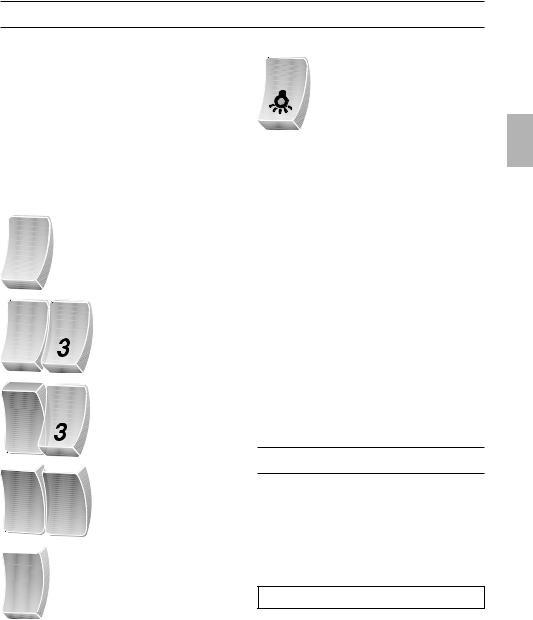
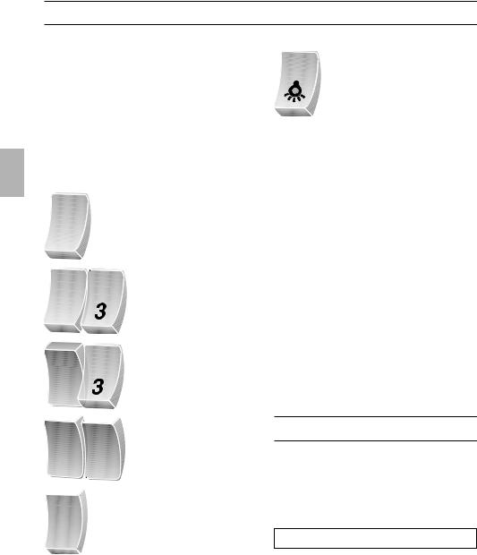
Operating controls on different models:
1 |
Level 1 |
2 |
Level 2 |
|
|
2 |
Level 1 |
|
Light:
0 |
OFF |
|
ON |
Note: The light can be switched on at any time, including when the vapour extractor tray has been pushed back into the hood.
|
2 |
|
Level 2 |
|
|
|
|
|
|
|
Level 3 |
|
|
|
|
|
2 |
|
|
|
3 |
|
|
|
|
|
|
|
|
|
|
|
|
|
|
|
|
|
|
|
|
|
|
|
3 |
|
Level 3 |
|
1 |
|
Level 1 |
|
2 |
|
Level 2 |
Switching the ventilator OFF:
Push the vapour extractor tray back in as far as it will go.
Note: The next time that the tray is pulled out, the ventilator will start up at the power level to which it was last set.
If you encounter a problem
If you have any questions or if a fault occurs, please call Customer Service.
(See list of Customer Service representatives).
When you call, please quote the following:
E-Nr. FD
Enter the relevant numbers into the box above. The E-Nr. (product no.) and FD (production date) are shown on the nameplate which can be seen inside the extractor hood after the filter frame has been detached.
5

Filters and maintenance
Various types of grease filter can be used to absorb the grease contained in the vapours produced during cooking.
The filter frame must be detached before the grease filter can be renewed.
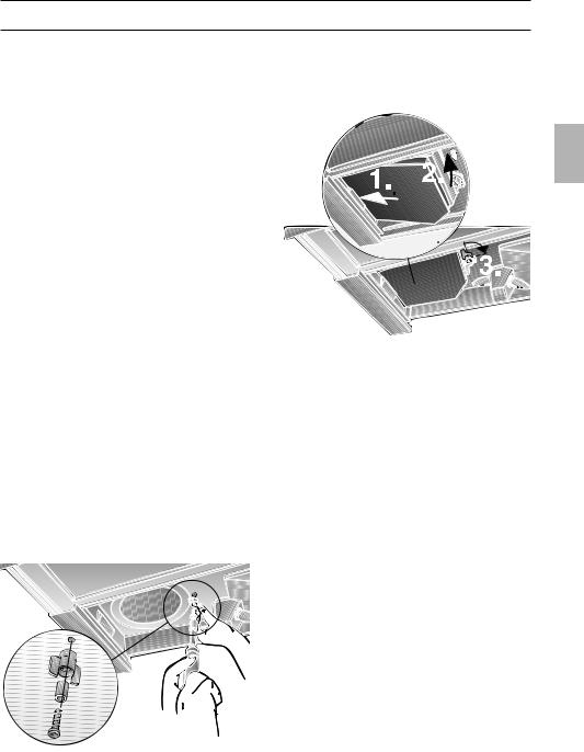
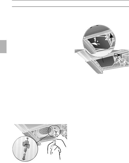
Detaching and re-attaching the filter frame:
Detaching the frame:
1.Open the cupboard door.
2.Place your fingers in the recessed grips in the inspection window, push the filter frame towards the front and then pull it all the way out.
2. |
1. |
Re-attaching the frame:
1.Insert the filter frame into the housing and push it in as far as it will go.
2.Close the cupboard door.
Fleece grease filter:
The filter mat is made from material that is itself virtually non-inflammable.
Caution:
As it becomes more and more saturated with grease however, the filter becomes increasingly inflammable. The efficiency of the extractor hood can also be adversely affected.
Important:
Renewing the fleece filter at appropriate intervals prevents the possibility of it catching fire as a result of a build-up of heat, such as occurs when deep-fat frying or roasting is taking place.
6
Renewing the fleece filter:
Under normal operating conditions
(1 to 2 hours per day), the fleece filter will require replacing after 8 to 10 weeks.
Printed fleece filters must be renewed no later than when the coloured printing has started to fade.
Use only original replacement filters.
In so doing you will ensure that safety regulations are upheld and the extractor hood performs as effectively as possible.
Removing/inserting the fleece filter:
1.Remove the wire frame.
2.Exchange the fleece filter.
3.Refit the wire frame.
Metal grease filter:
The filter mat is made of non-combustible metal.
Caution:
As it becomes more and more saturated with grease, the filter also becomes increasingly inflammable. The efficiency of the extractor hood can also be adversely affected.
Important:
By cleaning the metal grease filters at appropriate intervals, the possibility of them catching fire as a result of a build-up of heat such as occurs when deep-fat frying or roasting is taking place, is reduced.
Cleaning the metal filter:
Under normal operating conditions (1 to 2 hours per day), the metal grease filter will require cleaning after 8 to 10 weeks.
Filters and maintenance
The filter can be cleaned in a dishwasher.
This can however cause slight discoloration.
Important:
Metal filters that are heavily saturated with grease should not be cleaned at the same time as any crockery, etc.
If the filter mat is going to be cleaned by hand, soak it first of all in a hot detergent solution for several hours.
Clean the filter with a brush, rinse it off thoroughly and allow it to drip dry.
Use only original replacement filters.
In so doing you will be ensuring that the extractor hood performs as effectively as possible.
Removing/inserting the metal grease filter:
See details for removing/inserting the fleece filter.
Activated carbon filter:
For neutralising odours when hood is used in recirculating-air mode.
The activated carbon filter is installed above the grease filter inside the extractor hood.
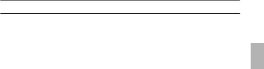
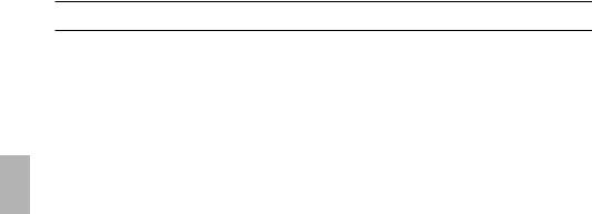
Inserting/removing the filter:
1.Remove the filter frame
(see details on previous page).
2.Place wing nut and sleeve over screw, insert into housing and tighten firmly (applies only when installing filter for first time).
– Screw, sleeve and wing nut are enclosed with the activated carbon filter –.
3.Hook the activated carbon filter into the left-hand side of the extractor hood housing, push the other side upwards and secure in place with the wing nut.
4. Re-attach the filter frame.
To remove the activated carbon filter, proceed in reverse order.
Renewing the activated carbon filter:
Under normal operating conditions (1 to 2 hours per day), the activated carbon filter will require replacing approximately once per year. Replacement filters can be obtained from specialist retailers
(see Optional accessories).
Use only original replacement filters.
In so doing you will be ensuring that the extractor hood performs as effectively as possible.
Disposing of the old activated carbon filter:
Activated carbon filters do not contain any pollutants and can be disposed of with domestic refuse.
7

Cleaning and care
Disconnect the extractor hood from the electricity supply by pulling out the mains plug or switching it off at the fuse box.
At the same time as you clean the grease filters, clean off any grease from all accessible parts of the housing. This significantly reduces the fire hazard and ensures that the extractor hood performs as effectively as possible.
Use a hot detergent solution or a mild window cleaner to clean the canopy of the extractor hood.
Do not scrape off any dirt that has dried on but loosen it up with a damp cloth.
Do not use abrasive cleaning agents or sponges that could cause scratches.
Note: Do not use alcohol (spirit) on plastic parts, otherwise the surface may become matt in appearance.
Caution: Ensure that the kitchen is adequately ventilated. Avoid naked flames!
Clean the operating buttons with a mild soapy solution and a soft, damp cloth only. Do not use stainless-steel cleaner to clean the operating buttons.
Stainless steel surfaces:
Use a mild non-abrasive stainless steel cleaner.
Clean the surface in the same direction as it has been ground and polished.
Do not use any of the following to clean stainless steel surfaces: abrasive sponges, cleaning agents containing sand, soda, acid or chloride!
Aluminium, painted and plastic surfaces:
Use a soft, non-linting window cloth or micro-fibre cloth.
Do not use dry cloths.
Use a mild window cleaning agent.
Do not use aggressive, acidic or caustic cleaners.
Do not use abrasive agents.
For appliances with a glass plate in the pull-out vapour extractor:
The glass plate is easily removed and can be cleaned in a dishwasher.
To remove the lugs, push outwards.
Replacing the light bulb
1.Switch off the extractor hood and pull out the mains plug or switch off the electricity supply at the fuse box.
2.Pull out the extractor hood and detach the filter frame.
3.Replace the light bulbs. (Standard candle bulbs, max. 40 W, E14 socket).
4.Re-attach the filter frame.
5.Plug appliance into mains again or switch on at the fuse box.
8
Installation Instructions:
Important information
Old appliances are not worthless rubbish. Valuable raw materials can be reclaimed by recycling old appliances. Before disposing of your old appliance, render it unusable.
You received your new appliance in a protective shipping carton. All packaging materials are environmentally friendly and recyclable. Please contribute to a better environment by disposing of packaging materials in an environmentally-friendly manner.
Please ask your dealer or inquire at your local authority about current means of disposal.
The extractor hood can be used in exhaust air or circulating air mode.
Always mount the extractor hood over the centre of the hob.
Minimum distance between electric hob and bottom edge of extractor hood:
430 mm, Fig. 1.
Additional information concerning gas cookers:
When installing gas hotplates, comply with the relevant national statutory regulations (e.g. in Germany: Technische Regeln Gasinstallation TRGI).
Always comply with the currently valid regulations and installation instructions supplied by the gas appliance manufacturer.
Only one side of the extractor hood may be installed next to a high-sided unit or high wall. Gap at least 50 mm.
The installation of the extractor hood above gas cooking devices, at a minimum height of 650 mm – Fig. 1 – is permitted provided that the following nominal heat loads (Hs) are not exceeded:
Gas cookers |
|
Load of one hotplate |
max. 03.0 kW |
Load of all hotplates |
max. 08.3 kW |
Load of the oven |
max. 03.9 kW |
Gas hobs |
|
Load of one hotplate |
max. 03.9 kW |
Load of all hotplates |
max. 11.3 kW |
Gas ceramic hotplate
The nominal heat load specifications do not apply to closed gas ceramic hobs. Always observe the specifications of the hob manufacturer.
Solid-fuel cookers
The maximum nominal heat loads and the minimum distance are the same as for gas cookers.
The extractor hood must not be installed over a solid fuel cooker – a potential fire hazard (e.g. flying sparks) – unless the cooker features a closed, non-removable cover and all national regulations are observed.
The smaller the gap between the extractor hood and hotplates, the greater the likelihood that droplets will form on the underside of the extractor hood.
9
Prior to installation
Exhaust-air mode
100 |
100 |
100 |
120 |
120 |
|
120 |
|
|
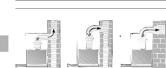
The exhaust air is discharged upwards through a ventilation shaft or directly through the outside wall into the open.
DExhaust air must not be discharged via a smoke or exhaust gas flue which is already in use or via a shaft which is used for ventilating rooms in which fireplaces are located.
Discharge exhaust air in accordance with official and statutory regulations (e.g. national building regulations).
Discharge of air into smoke or exhaust air flues which are not in use requires the consent of a heating engineer.
DIf the extractor hood is operated in exhaust-air mode at the same time as a flue-type heater (e.g. gas, oil or solid-fuel heater, instantaneous water heater, boiler), ensure that there is an adequate air supply which the heater requires for combustion.
Safe operation is possible provided that the partial vacuum in the room in which the heater is installed does not exceed 4 Pa (0.04 mbar).
This can be achieved if the combustion air is able to flow through non-lockable openings, e.g. in doors, windows and in conjunction with an air supply/air-intake wall box or by other technical procedures such as reciprocal interlocking.
If the air intake is inadequate, there is a risk of poisoning from combustion gases which are drawn back into the room.
An air-intake/exhaust-air wall box by itself is no guarantee that the limiting value will not be exceeded.
Note: When assessing the overall requirement, the combined ventilation system for the entire household must be taken into consideration. This rule does not apply to the use of cooking appliances, such as hobs and gas cookers.
The extractor hood can be used without restriction in circulating air mode – with an activated carbon filter.
For exhaust air mode a one-way flap should be installed in the extractor hood unless already installed in the exhaust air pipe or wall box.
If a one-way flap is not enclosed with the extractor hood, you purchase one from your dealer.
If the exhaust air is conveyed through the outside wall, a telescopic wall box should be used.
10
Prior to installation
For optimum extractor hood efficiency:
Short, smooth air exhaust pipe.
As few bends in the pipe as possible.
Diameter of pipe to be as large as possible (ideal is l 120 mm ) and no tight bends in pipe.
If long, rough exhaust-air pipes, many pipe bends or smaller pipe diameters are used, the air extraction rate will no longer be at an optimum level and there will be an increase in noise.
Round pipes: We recommend
Internal diameter at least. 120 mm.
Flact ducts must have an internal cross-section that equates to that of round pipes with a 100/120 mm internal diameter.
There should be no sharp bends. l 100 mm approx. 078 cm2
l 120 mm approx. 113 cm2
If pipes have different diameters:
Insert sealing strip.
For exhaust-air mode, ensure that there is an adequate supply of fresh air.
Exhaust outlet connection:
Pipe diameter: 100 or 120 mm.
Insert the enclosed outlet connector and twist it as far as it will go.
If the pipe diameter is 120 mm, cut out the inner part of the outlet connector.
Exhaust air flows upwards:
Cut a hole in the top of the wall cupboard, including a groove for the mains
cable.
– Template OI lis enclosed –.
|
115/130 |
|
|
|
|
|
|
|
|
125 |
|
|
|
|
|
|
|
200 |
|
|
|
|
120 |
|
|
|
|
|
|
|
100 |
180 |
|
|
|
|
|
40 |
75 |
61,5 |
|
|
|
257 |
|
80 |
|
|
|
|
|
|
|||
|
|
|
|
|
|
|
|
196 |
|
|
20 |
|
542 |
|
212 |
|
|
|
|
|
|||
|
|
|
|
500 |
|
|
|
|
|
|
|
|
|
32 |
|
|
|
|
|
|
|
|
|
|
|
. |
|
|
|
|
|
600 |
m |
in |
|
|
|
|
|
280 |
|
|
|
|
259 |
||
|
|
|
|
|
|
|
|
|
|
|
|
|
|
|
280 |
|
|
|
|
|
|
40 |
450 |
|
|
|
|
|
|
|
|
|
|
|
|
598 |
|
|
|
Exhaust flows straight out at the back:
– inside the wall cupboard –.
Cut a hole in the rear panel of the wall cupboard, including a groove for the mains cable.
Circulating-air mode
With activated carbon filter if exhaust-air mode is not possible.
The complete
installation set can be obtained from specialist outlets. The corresponding accessory numbers can be found at the end of these operating instructions.
Preparation:
Cut a hole in the top of the wall cupboard, including a groove for the mains cable.
– Template OI is enclosed –.
11
Preparing the wall cupboard
Ensure that there is a minimum gap between hob and extractor hood of 650 mm (for gas hobs) or 430 mm (for electric hobs).
This extractor hood has been designed for installation inside a wall cupboard with the following dimensions:
Width: 600 mm
Depth: 280 bis 350 mm Height:at least 280 mm.
Preparation:
1.Remove bottom panel of cupboard – if fitted.
The stability of the cupboard must be maintained.
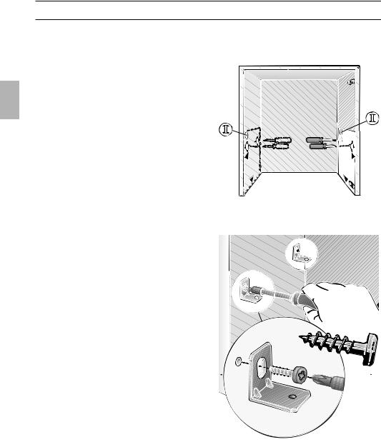
2.Mark two points – right and left – on the inside of the cupboard where the hood is to be mounted, and start the hole with a gimlet.
Details for drilling:
l 2 mm – max. 10 mm deep.
Use enclosed template OII for marking points where hood is to be mounted.
Caution:
The mounting points shown on the template have been configured in such a way as to allow a 20 mm thick handle to be attached flush with the front edges of the cupboard.
If no handle is going to be attached, the mounting points must be brought forward by 20 mm.
If the cupboard depth is greater than 280 mm, the hood can be mounted further back,
. . . if the light strip under the cupboard
. . . units is mounted further back,
. . . if the handle is more than 20 mm thick.
To do this, move the mounting points further towards the back by the corresponding distance.
3.Align the 4 enclosed mounting brackets and screw them on tight.
12

Installation inside the wall cupboard |
|
|
1. Align the cupboard doors if the hinges |
4. Install a shelf immediately above the |
|
will no longer be accessible after the |
||
extractor hood. Cut holes for the pipe |
||
extractor hood has been fitted. |
||
connection and the mains cable. |
||
|
2.Place the extractor hood onto the mounting brackets and push it into the
cupboard.
20 |
20 |
Important: The extractor hood must be firmly seated on the 4 mounting brackets.
3. Loosely screw in the 4 enclosed screws. Align the extractor hood and then tighten screws.
Check that the extractor hood is firmly fitted into the cupboard.
mind.15 |
.475 |
|
mind |
If the shelf is permanently fixed inside the cupboard, 4 holes must be drilled to provide access to the 4 mounting screws for the extractor hood.
5.Route the mains cable through the hole in the wall cupboard and connect up the exhaust pipe.
6.Connect up the extractor hood to the mains.
7.If no handle is going to be attached to the vapour extractor, seal off the 3 holes
with the enclosed caps.
13
Installation inside the wall cupboard
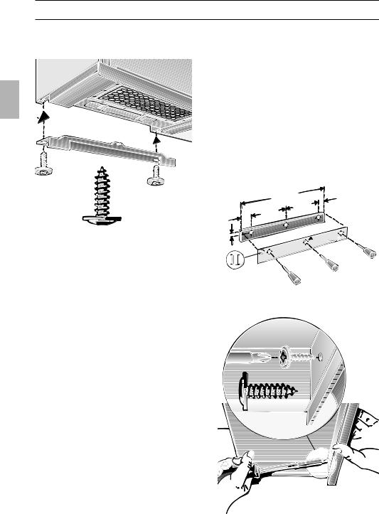
8.Cut the wall masking strip down to size if necessary and screw it onto the wall cupboard.
Attaching a handle to the vapour extractor:
A handle can be attached to the vapour extractor.
This handle can either be a wooden strip that matches the kitchen cupboards or a the handle that is available as an optional accessory (see section on optional accessories in the user instructions).
1.Use the enclosed template OIII to mark the 3 mounting points on the handle and start the hole with a gimlet. Details for drilling:
l 2 mm – max. 10 mm deep.
598 |
44 |
|
230 |
94 |
230 |
|
|
20 |
|
2.Align handle and attach it to the extractor with the 3 enclosed screws.
14
Installation inside the wall cupboard
Note: The extractor hood housing inside the wall cupboard can be boarded up (e.g. with chipboard).
Please observe the following:
–The shelf must not be rest upon the extractor hood housing.
–The board at the front should not be attached to the housing.
–Ensure that access is possible for replacing filters or by Customer Service.
Weight in kg:
|
|
|
|
|
|
|
|
|
|
Exhaust air |
|
|
|
Re-circulating air |
|
|
|
|
|
|
|
|
|
|
|
|
|
|
|
|
|
|
|
|
|
|
|||
|
7,0 |
|
|
8,0 |
|
||
|
|
|
|
|
|
|
|
|
|
|
|
|
|
|
|
The manufacturer reserves the right to make design alterations in the interests of technical development.
Electrical connection
WARNING: THIS APPLIANCE MUST BE EARTHED
IMPORTANT: Fitting a Different Plug:
The wires in the mains lead are coloured in accordance with the following code:
Green and Yellow |
– |
Earth |
Blue |
– |
Neutral |
Brown |
– |
Live |
If you fit your own plug, the colours of these wires may not correspond with the identifying marks on the plug terminals.
This is what you have to do:
1.Connect the green and yellow (Earth)
wire to the terminal in the plug marked ‘E’ or with the symbol (  ), or coloured green or green and yellow.
2.Connect the blue (Neutral) wire to the terminal in the plug marked ‘N’ or coloured black.
3.Connect the brown (Live) wire to the terminal marked ‘L’, or coloured red.
The extractor hood may only be connected to an earthed socket that has been installed according to the relevant regulations. If possible, site the earthed socket directly above the wall cupboard or in its immediate vicinity.
Electrical specifications:
Are to be found on the name plate inside the appliance after removal of the filter frame.
Before undertaking any repairs, always disconnect the extractor hood from the electricity supply.
Length of the connecting cable: 1,30 m.
If it is necessary to wire the extractor hood directly into the mains:
The extractor hood may only be connected up by a qualified electrician approved by the appropriate electricity company.
A separator must be installed in the household circuit. A suitable separator is a switch that has a contact gap of more than 3 mm and interrupts all poles. Such devices include circuit breakers and contactors.
This extractor hood complies with EC |
|
regulations relating to the suppression of |
|
RF interference. |
15 |
|
Käyttöohje:
Laitteen kuvaus
Suodatinkehys |
Tuuletustehon |
||
|
|
valitsimet |
|
Yläkaappi |
Höyrylippa |
Valaistuksen |
|
|
|
|
kytkin |
Toimintatavat |
|
|
|
Hormiliitäntäinen: |
|
|
|
Liesituuletin imee keittiöhöyryn ja johtaa sen rasvasuodattimen läpi ulkoilmaan.
Rasvasuodatin kerää keittiöhöyryn kiinteät aineet.
Keittiö pysyy puhtaana rasvasta ja hajusta.
DKun liesituuletin on hormiliitäntäinen ja samanaikaisesti käytössä on huoneilmaa tarvitseva tulisija (kuten esim. kaasu-, öljytai hiililämmitteinen lämmityslaite tai vedenlämmitin), on huolehdittava riittävästä tuloilman saannista, jotta tulisija saa tarpeeksi ilmaa palamista varten.
Vaaraton toiminta on mahdollista, jos tulisijan sijoitushuoneessa alipaine ei ole korkeampi kuin 4 Pa (0,04 mbar).
Toimintatavat
Tähän päästään, jos palamiseen tarvittava ilma voi aina virrata avoimien aukkojen kautta, joita on esim. ovissa, ikkunoissa, tuloja poistoilman liitännöissä, tai ilmanvirtaus on järjestetty muita teknisiä toimenpiteitä käyttäen, esim. keskinäisen lukituksen tms. avulla.
Jos tuloilman saanti ei ole riittävä, aiheuttavat takaisinimetyt palamiskaasut myrkytysvaaran.
Tuloilma-/poistoilmahormi ei yksistään takaa raja-arvojen pysymistä annetuissa rajoissa.
Huomautus: Tilannetta arvioitaessa on aina otettava huomioon asunnon ilmastoinnin kokonaisratkaisu. Tämä sääntö ei koske keittolaitteiden, esim. keittotason tai kaasulieden, käyttöä.
Jos liesituuletinta käytetään aktiivihiilisuodattimen kanssa, jolloin ilma palautetaan huonetilaan, on toiminta mahdollista ilman rajoitusta.
Huoneilmaan palauttava:
Tässä toimintatavassa on asennettava aktiivihiilisuodatin (katso: Suodatin ja
huolto).
Täydellisen asennussarjan ja varasuodattimia saat kodinkoneliikkeistä.
Lisävarusteiden numerot löydät tämän käyttöohjeen lopusta.
Tuuletin imee keittiöhöyryn ja johtaa sen rasvaja aktiivihiilisuodattimen puhdistamana takaisin keittiöön.
Rasvasuodatin kerää keittiöhöyryn kiinteät aineet.
Aktiivihiilisuodatin sitoo hajuaineet ja kosteuden.
16

Ennen ensimmäistä käyttöä
Tärkeitä ohjeita:
Tämä käyttöohje on tarkoitettu eri mallille. Tästä johtuen on mahdollista, että kaikki tässä kuvatut ominaisuudet ja varusteet eivät koske hankkimaasi laitetta.
Tämä liesituuletin vastaa sähkölaitteita koskevia turvallisuusohjeita.
Korjauksia saa suorittaa vain alan ammattimies.
Ammattitaidottomasti tehdyt korjaukset voivat aiheuttaa laitteen käyttäjälle suuria vaaroja.
Lue huolellisesti käyttöohjeet, ennen kuin käytät uutta laitetta.
Niissä on tärkeää turvallisuuteen ja käyttöön liittyvää tietoa sekä laitteen hoito-ohjeita.
Säilytä hyvin käyttöja asennusohjeet, jotta laitteen mahdollinen uusi omistaja voi tutustua niihin.
Jos laite on vaurioitunut, sitä ei saa ottaa käyttöön.
Liitännän ja käyttöönoton saa suorittaa vain alan ammattimies.
Jos liesituulettimen liitäntäjohto vioittuu, sen saa vaihtaa vain valmistaja tai valtuutettu huoltoliike tai huoltomies vahinkojen välttämiseksi.
Toimita pakkausmateriaali lajiteltuna asianmukaiseen keräyspisteeseen (katso Asennusohje).
Käytä liesituuletinta vain yhdessä paikoilleen asennettujen lamppujen kanssa.
Vaihda rikki menneiden lamppujen tilalle heti uudet jäljellä olevien lamppujen ylikuormittumisen välttämiseksi.
Liesituuletinta ei saa käyttää ilman rasvasuodatinta.
Ylikuumentuneet rasvat tai öljyt syttyvät helposti palamaan.
Käytä siksi öljyä tai rasvaa ruoan, esim. ranskan perunoiden, valmistukseen vain valvonnan alaisena.
Älä suorita liekitystä liesituulettimen alla.
! Nousevat liekit aiheuttavat palovaaran rasvasuodattimessa.
Liesituulettimen käyttö kiinteillä polttoaineilla (hiili, puu tai tms.) toimivien tulisijojen yläpuolella on sallittu vain varauksin (katso asennusohje).
Kaasulla toimivat keittotasot / liedet
Kaasulieden polttimia on aina käytettävä asianmukaisesti.
Tärkeää:
Kaasupolttimien liekkien on aina oltava peitettynä keittoastioilla.
Avoimien kaasuliekkien aiheuttama
!voimakas kuumuus saattaa vahingoittaa liesituuletinta.
17
Liesituulettimen käyttö
Näin keittiöhöyry poistuu tehokkaimmin:
Käynnistä tuuletin alkaessasi valmistaa ruokaa.
Kytke tuuletin toiminnasta vasta muutaman minuutin jälkeen lopetettuasi ruoanvalmistuksen.
Tuulettimen käynnistys:
1.Vedä ulos höyrylippa.
Liesituuletin on toiminnassa.
2.Valitse haluamasi tuuletusteho.
Eri mallien tuuletustehon valitsimet:
1 |
Tuuletusteho 1 |
2 |
Tuuletusteho 2 |
|
|
2 |
Tuuletusteho 1 |
|
Valaisin: |
|
0 |
Pois |
|
Päällä |
Huomautus: Valaisinta voi käyttää milloin tahansa, myös kun höyrylippa on työnnettty sisään.
|
2 |
|
Tuuletusteho 2 |
|
|
|
|
|
|
|
Tuuletusteho 3 |
|
|
|
|
|
2 |
|
|
|
3 |
|
|
|
|
|
|
|
|
|
|
|
|
|
|
|
|
|
|
|
|
|
|
|
3 |
|
Tuuletusteho 3 |
|
1 |
|
Tuuletusteho 1 |
|
2 |
|
Tuuletusteho 2 |
Tuulettimen kytkeminen toiminnasta:
Työnnä höyrylippa vasteeseen asti.
Huomautus: Kun vedät höyrylipan taas ulos, tuuletin toimii viimeksi valitulla teholla.
Häiriöt
Häiriön sattuessa tai jos sinulla on kysyttävää, soita asiakaspalveluun.
(Katso asiakaspalvelupisteluettelo).
Ilmoita soittaessasi:
E-n:o FD
Merkitse numerot ylläoleviin ruutuihin. Numerot löydät liesituulettimen sisäosan tyyppikilvestä, kun suodatinritilä on irrotettu.
18

Suodatin ja huolto
Keittiöhöyryn rasvaisten osasten keräämiseen voidaan käyttää erilaisia rasvasuodattimia.
Kun aiot vaihtaa uuden rasvasuodattimen, irrota ensin suodatinkehys.
Suodatinkehyksen irrotus ja kiinnitys:
Irrotus:
1.Avaa kaapin ovet.
2.Työnnä suodatinkehystä tarkistuslasissa olevista tartuntasyvennyksistä eteenpäin ja vedä kehys sitten ulos aivan eteen.
2. |
1. |
Kiinnitys: |
1.Aseta suodatinkehys paikoilleen tuulettimen runkoon ja työnnä sisään.
2.Sulje kaapin ovet.
Kuitukankainen rasvasuodatin:
Suodatin on vaikeasti syttyvää materiaalia.
Huom.!:
Syttymisvaara kasvaa, kun rasva kyllästää suodatinta; liesituulettimen toiminta saattaa tällöin heikentyä.
Tärkeää:
Kun vaihdat kuitukankaisen rasvasuodattimen ajoissa, vältyt palovaaralta, jonka friteeraamisen tai voimakkaan paistamisen yhteydessä syntyvä kuumuus voi aiheuttaa.
Kuitukankaisen rasvasuodattimen vaihto:
Vaihda suodatin normaalikäytössä (1 – 2 tuntia päivittäin) 8 – 10 viikon välein. Kun suodattimessa on painatus, vaihda
suodatin viimeistään silloin, kun värillinen painatus tulee selvästi näkyviin.
Käytä vain alkuperäisiä suodattimia.
Ne täyttävät turvallisuusmääräykset ja takaavat parhaan mahdollisen toiminnan.
Kuitukankaisen rasvasuodattimen irrotus ja kiinnitys:
1.Irrota lankasäleikkö.
2.Vaihda kuitukankainen rasvasuodatin.
3.Kiinnitä lankasäleikkö takaisin paikalleen.
Metallinen rasvasuodatin:
Suodattimet ovat palamatonta metallia.
Huom.!:
Syttymisvaara kasvaa, kun rasva kyllästää suodatinta; liesituulettimen toiminta saattaa tällöin heikentyä..
Tärkeää:
Kun vaihdat metallisen rasvasuodattimen ajoissa, vältyt palovaaralta, jonka friteeraamisen tai voimakkaan paistamisen yhteydessä syntyvä kuumuus voi aiheuttaa.
Metallisen rasvasuodattimen puhdistus:
Puhdista suodatin normaalikäytössä 1 – 2 tuntia päivittäin) 8 – 10 viikon välein.
19
Suodatin ja huolto
Voit pestä suodattimen astianpesukoneessa.
Suodattimen väri saattaa tällöin hieman muuttua.
Tärkeää:
Voimakkaasti kyllästynyttä metallista rasvasuodatinta ei saa pestä yhdessä astioiden kanssa.
Kun puhdistat suodattimen käsin, anna sen ensin liota kuumassa pesuliuoksessa useita tunteja.
Puhdista sitten suodatin harjaamalla, huuhtele hyvin ja anna valua kuivaksi.
Käytä vain alkuperäisiä suodattimia.
Ne täyttävät turvallisuusmääräykset ja takaavat parhaan mahdollisen toiminnan.
Metallisen rasvasuodattimen irrotus ja kiinnitys:
Katso kuitukankaisen suodattimen irrotus ja kiinnitys.
Aktiivihiilisuodatin:
Sitoo hajuaineet ja kosteuden kiertoilmatoiminnan yhteydessä.
Aktiivihiilisuodatin asennetaan liesituulettimeen rasvasuodattimen päälle.
Irrotus ja kiinnitys:
1.Irrota suodatinkehys. (katso Suodatin ja huolto).
2.Työnnä ruuvi siipimutterin ja hylsyn läpi ja kiinnitä runkoon (tarpeellista vain ensiasennuksen yhteydessä).
– Ruuvi ja siipimutteri ovat aktiivihiilisuodattimen mukana –.
3.Aseta aktiivihiilisuodatin liesituulettimeen vasemman puoleisen sivun yläosaan, käännä suodatin ylös ja lukitse paikoilleen siipimutterilla.
4.Kiinnitä suodatinkehys takaisin paikoilleen.
Irrota suodatin päinvastaisessa järjestyksessä.
Aktiivihiilisuodattimen vaihto:
Normaalikäytössä (1 – 2 tuntia päivittäin) aktiivihiilisuodatin on vaihdettava noin kerran vuodessa. Aktiivihiilisuodattimia saat
ALAN LIIKKEISTÄ (katso kohta Lisävarusteet).
Käytä vain alkuperäistä suodatinta.
Se takaa parhaan mahdollisen toiminnan.
Käytöstä poistetun aktiivihiilisuodattimen hävittäminen:
Aktiivihiilisuodattimissa ei ole haittaaineita. Ne voi hävittää esim. yhdessä muiden kotitalousjätteiden kanssa.
20
Puhdistus ja hoito
Irrota liesituuletin sähköverkosta joko vetämällä pistoke pistorasiasta tai katkaisemalla virta sulakkeesta.
Puhdista rasvasuodattimien puhdistuksen yhteydessä puhdistettavissa olevat rungon osat niihin kertyneestä liasta.
Näin ehkäistään syttymisvaara ja toiminta pysyy parhaana mahdollisena.
Pese liesituuletin kuumalla pesuaineliuoksella tai miedolla ikkunanpesuaineella.
Älä raaputa kuivaa likaa pois, vaan liota se irti kostealla liinalla.
Älä käytä hankaavia puhdistusaineita tai sieniä.
Huom.!: Älä puhdista muovipintoja alkoholilla (spriillä), niihin voi jäädä himmeitä läikkiä
Varo! Huolehdi keittiön riittävästä tuuletuksesta, ei avotulta.
Puhdista kytkimien painikkeet ainoastaan miedolla pesuaineliuoksella ja pehmeällä, kostealla liinalla.
Älä puhdista muovipintoja ruostumattoman teräksen puhdistusaineilla.
Teräspinnat:
Käytä mietoa ruostumattoman teräksen puhdistusainetta, joka ei hankaa.
Puhdista vain hiontasuunnassa.
Älä puhdista teräspintoja hankaavilla sienillä äläkä hiekka-, sooda, happotai klooripitoisilla pesuaineilla!
Alumiinija muovipinnat:
Käytä pehmeää ikkunatai mikrokuituliinaa, josta ei irtoa nukkaa.
Älä käytä kuivia pyyhinliinoja.
Käytä mietoa ikkunanpesuainetta
Älä käytä syövyttäviä, happotai emäspitoisia puhdistusaineita.
Älä käytä hankaavia puhdistusmenetelmiä.
Liesituulettimet, joiden höyrylipassa on lasilevy:
Lasilevyn voi irrottaa helposti ja sen voi pestä astianpesukoneessa.
Irrota lasilevy työntämällä kiinnittimet ulospäin.
Lampun vaihto
1.Kytke liesituuletin pois päältä ja irrota sähköverkosta vetämällä verkkopistoke pistorasiasta tai katkaisemalla virta sulakkeesta.
2.Vedä ulos höyrylippa ja irrota suodattimen kehys.
3.Vaihda lamppu.
(Tavallinen kynttilälamppu max. 40 W, kanta E 14).
4.Aseta suodatinkehys takaisin paikalleen.
5.Pane pistoke pistorasiaan tai kytke virta sulakkeesta.
21
Asennusohje:
Tärkeitä ohjeita
Käytöstä poistetut laitteet voidaan käyttää hyväksi toimittamalla ne kierrätykseen, jolloin niistä saadaan raaka-aineita uusiokäyttöön.
Tee käytöstä poistettu laite käyttökelvottomaksi ennen hävittämistä.
Kuljetussyistä uusi liesituulettimesi on pakattu sitä suojaavaan pakkaukseen. Kaikki pakkauksessa käytetyt materiaalit ovat ympäristöystävällisiä ja ne voidaan kierrättää. Suojele ympäristöä hävittämällä pakkausmateriaali ympäristöystävällisesti.
Myyntiliike tai kunnan tai kaupungin jätehuoltoasioista vastaavat henkilöt antavat neuvoja paikallisesta jätehuollosta.
Liesituuletinta voi käyttää hormiliitäntäisenä ja huoneilmaan palauttavana.
Asenna liesituuletin aina keittotason keskikohdan yläpuolelle.
Sähkölieden keittotason ja liesituulettimen välisen etäisyyden tulee olla vähintään:
430 mm, kuva 1.
Kaasulla toimivia keittotasoja ja liesiä koskevia lisäohjeita:
Noudata kaasulla toimivien keittotasojen asennuksessa maakohtaisia lakisääteisiä määräyksiä (esim. Saksassa: Tekniset määräykset kaasuasennuksista TRGI).
Noudata voimassaolevia asennusmääräyksiä ja kaasulaitteiden valmistajien asennusohjeita.
Asenna liesituuletin siten, että ainoastaan sen toisella puolella on korkea kaappi tai seinä. Vähimmäisetäisyyys 50 mm.
Liesituulettimien asennus on sallittu kaasulla toimivan keittotason yläpuolelle vain, kun vähimmäisetäisyys on 650 mm - kuva 1 - ja kun seuraavia nimellisläpökuormituksia (Hs) ei ylitetä:
Kaasuliedet |
|
Yhden keittoalueen |
|
kuormitus |
max. 03,0 kW |
Kaikkien keittoalueiden |
|
kuormitus |
max. 08,3 kW |
Uunin kuormitus |
max. 03,9 kW |
Kaasulla toimivat keittolevyt
Yhden keittoalueen
kuormitus |
max. 03,9 kW |
Kaikkien keittoalueiden |
|
kuormitus |
max. 11,3 kW |
Keraaminen kaasukeittotaso
Annetut tiedot nimellislämpökuormituksista eivät päde suljettujen keraamisten kaasukeittotasojen suhteen. Ehdottomasti noudatettava keittotason valmistajan ohjeita.
Kiinteillä polttoaineilla toimivat liedet
Tällöin pätevät samat maksimi nimellislämpökuormitukset ja vähimmäisetäisyys kuin kaasuliesien kohdalla.
Liesituulettimen asennus on sallittu esim. kipinöinnistä aiheutuvan palovaaran vuoksi kiinteillä polttoaineilla toimivien liesien yläpuolelle vain, jos liesi on varustettu suljetulla kiinteällä kannella ja jos noudatetaan maakohtaisia määräyksiä. Tämä rajoitus ei koske kaasuliesiä eikä kaasukeittotasoja.
Mitä pienempi liesituulettimen ja keittotason välinen etäisyys on, sitä suurempi on mahdollisuus, että ylös kohoava vesihöyry muodostaa pisaroita liesituulettimen alaosaan.
22
 Loading...