


INSTALLATION INSTRUCTIONS
ROOF OR WALL VENTILATOR
MODELDHG6003UC& DHG1003UC
PLEASE READ ENTIRE INSTRUCTIONS BEFORE PROCEEDING.
IMPORTANT: Save these instructions for the Local Electrical Inspector’s use. INSTALLER: Please leave these Installation Instructions with this unit for the owner. OWNER: Please retain these instructions for future reference.
 SAFETYWARNING:Before servicing or cleaning unit, switch power off at the service panel and lock service disconnecting means to prevent power from being switched on accidentally. When the service disconnecting means cannot be locked, attach a tag to the service panel to indicate power has been switched off for maintenance.
 WARNING-TOREDUCETHE RISKOFFIRE,ELECTRICSHOCK, ORINJURYTOPERSONS,OBSERVETHEFOLLOWING:
A.Installation work and electrical wiring must be done by qualified person(s) in accordance with all applicable codes & standards, including fire-rated construction.
B.Sufficient air is needed for proper combustion and exhausting of gases through the flue (chimney) of fuel burning equipment to prevent back drafting. Follow the heating equipment manufacturers guideline and safety standards such as those published by the National Fire Protection Association (NFPA), and the American Society for Heating, Refrigeration and Air Conditioning Engineers
(ASHRAE), and the local code authorities.
C.When cutting or drilling into wall or ceiling, do not damage electrical wiring and other hidden utilities.
D.To properly exhaust air, be sure to duct air out side. Do not vent exhaust air into spaces within walls, ceilings, attics, crawl spaces, or garages.
WARNING: To reduce the risk of fire, use only metal ductwork.
CAUTION - For General Ventilating
Use Only. Do Not Use To Exhaust
Hazardous Or Explosive Materials And
Vapors.
Recommended for use only over conventional domestic gas and electric ranges, and
use with an approved Bosch Hood.
INSTALLATION:
1.Remove and discard shipping bracket (attached to motor mounts and inlet collar). Check to see if blower wheel turns freely. Do not replace top until installation is complete.
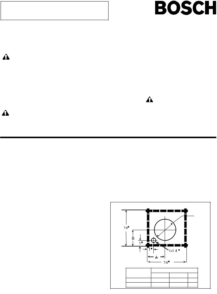
2.Provide a square cutout through the roof (or wall) as shown by the dashed lines, or cut a round hole to fit duct with a separate hole for electrical conduit as shown by solid lines in Fig. 1.
3.Install the remote ventilator with the discharge pointing down slope as shown in Figures 3 and 4. Follow standard roofing procedures. Install the ventilator so the discharge edge is on top of the shingles and the rear edge is underneath the shingles.
NOTE: The unit must be sealed between the roof (or wall) and the underside of the flange with roofing mastic to prevent leaks. For installation on a flat roof, or roofs with a pitch less than 1-1/2" in 12", install ventilator on the curb as shown in Fig. 2. Position the curb on flat roofs so that the discharge (low) end points away from prevailing wind.
4.Connect ventilator to the exhaust system with 8 inch diam. duct for DHG6003UC and 10" diam. duct for DHG1003UC and use adjustable elbow to adjust to roof angle. Tape all joints to prevent air leaks.
5.Connect ducting in the inlet to the ventilator with duct tape.
6.Clearance to combustible material is 0".
For wiring to all approved Bosch products, see Installation Instructions provided with that product.
ONCE INSTALLATION AND WIRING ARE COMPLETE:
1.Turn ventilator on High for 5 minutes to ensure proper installation.
2.Step to Medium & Low ensuring each speed setting.
3.Turn ventilator off.
Fig. 1 TOP VIEW Down Slope of Roof or Wall
|
|
|
|
|
|
|
|
|
|
|
|
|
|
|
|
|
|
|
|
|
|
|
|
|
|
|
|
|
|
|
|
|
|
|
|
|
|
|
|
|
|
|
|
|
|
|
|
|
|
|
|
|
|
|
|
|
|
|
|
|
|
|
|
|
|
|
|
|
|
|
|
|
|
|
|
|
|
|
|
|
|
|
|
|
|
|
|
|
|
|
|
|
|
|
|
|
|
|
|
|
|
|
|
|
|
|
|
|
|
|
|
|
|
|
|
|
|
|
|
|
|
|
|
|
|
|
|
|
|
|
|
|
|
|
|
|
|
|
|
|
|
|
|
|
|
|
|
|
|
|
|
|
|
|
|
|
|
|
|
|
|
|
|
|
|
|
|
|
|
|
|
|
|
|
|
|
|
|
|
|
|
|
|
|
|
|
|
|
|
|
|
|
|
|
|
|
|
|
|
|
|
|
|
|
|
|
|
|
|
|
|
|
|
|
|
|
|
|
|
|
|
|
|
|
|
|
|
|
|
|
|
|
|
|
|
|
|
|
|
|
|
|
|
|
|
|
|
|
|
|
|
|
|
|
|
|
|
|
|
|
|
|
|
|
|
|
|
|
|
|
|
|
|
|
|
|
|
|
|
|
|
|
|
|
|
|
|
|
|
|
|
|
|
|
|
|
|
|
|
|
|
|
|
|
|
|
|
|
|
|
|
|
|
|
|
|
|
|
|
|
|
|
|
|
|
|
|
|
|
|
|
|
|
|
|
|
|
|
|
|
|
|
|
|
|
|
|
|
|
|
|
|
|
|
|
|
|
|
|
|
|
|
|
|
|
|
|
|
|
|
|
|
|
|
|
|
|
|
|
|
|
|
|
|
|
|
|
|
|
|
|
|
|
|
|
|
|
|
|
|
|
|
|
|
|
|
|
|
|
|
|
|
|
|
|
|
|
|
|
|
|
|
|
|
|
|
|
|
|
|
|
|
|
|
|
|
|
|
|
|
|
|
|
|
|
|
|
|
|
|
|
|
|
|
|
|
|
|
|
|
|
|
|
|
|
|
|
|
|
|
|
|
|
|
|
|
|
|
|
|
|
|
|
|
|
|
|
|
|
|
|
|
|
|
|
|
|
|
|
|
|
|
|
|
|
|
|
|
|
|
|
|
|
|
|
|
|
|
|
|
|
|
|
|
|
|
|
|
|
|
|
|
|
|
|
|
|
|
|
|
|
|
|
|
|
|
|
|
|
|
|
|
|
|
|
|
|
|
|
|
|
|
|
|
|
|
|
|
|
|
|
|
|
|
|
|
|
|
|
|
|
|
|
|
|
|
|
|
|
|
|
|
|
|
|
|
|
|
|
|
|
|
|
|
|
|
|
|
|
|
|
|
|
|
|
|
|
|
|
|
|
|
|
|
|
|
|
|
|
|
|
|
|
|
|
|
|
|
|
|
|
|
|
|
|
|
|
|
|
|
|
|
|
|
|
|
|
|
|
|
|
|
|
|
|
|
|
|
|
|
|
|
|
|
|
|
|
|
|
|
|
|
|
|
|
|
|
|
|
|
|
|
|
|
|
|
|
|
|
|
|
|
|
|
|
|
|
|
|
|
|
|
|
|
|
|
|
|
|
|
|
|
|
|
|
|
|
|
|
|
|
|
|
|
|
|
|
|
|
|
|
|
|
|
|
|
|
|
|
|
|
|
|
|
|
|
|
|
|
|
|
|
|
|
|
|
|
|
|
|
|
|
|
|
|
|
|
|
|
|
|
|
|
|
|
|
|
|
|
|
|
|
|
|
|
|
|
|
|
|
|
|
|
|
|
|
|
|
|
|
|
|
|
|
|
|
|
|
|
|
|
|
|
|
|
|
|
|
|
|
|
|
|
|
|
|
|
|
|
|
|
|
|
|
|
|
|
|
|
|
|
|
|
|
|
|
|
|
|
|
|
|
|
|
|
|
|
|
|
|
|
|
|
|
|
|
|
|
|
|
|
|
|
|
|
|
|
Dimension |
|
|||||||||
|
|
|
Model |
A |
|
|
|
B |
C |
|||||||||||||||||||||
|
|
|
DHG6003UC |
5-11/16" |
6-1/8" |
|
|
9" |
||||||||||||||||||||||
|
|
|
DHG1003UC |
7-1/4" |
|
|
|
6-15/16" |
11" |
|||||||||||||||||||||
(Over)

Figure2 CURBFORROOF |
Figure3 |
Figure 4 |
|
|
|
|
||||||||||||||
|
|
|
|
|
|
|
|
|
|
|
|
|
|
|
|
|
|
|
|
|
|
|
|
|
|
|
|
|
|
|
|
|
|
|
|
|
|
|
|
|
|
|
|
|
|
|
|
|
|
|
|
|
|
|
|
|
|
|
|
|
|
|
|
|
|
|
|
|
|
|
|
|
|
|
|
|
|
|
|
|
|
|
|
|
|
|
|
|
|
|
|
|
|
|
|
|
|
|
|
|
|
|
|
|
|
|
|
|
|
|
|
|
|
|
|
|
|
|
|
|
|
|
|
|
|
|
|
|
|
|
|
|
|
|
|
|
|
|
|
|
|
|
|
|
|
|
|
|
|
|
|
|
|
|
|
|
|
|
|
|
|
|
|
|
|
|
|
|
|
|
|
|
|
|
|
|
|
|
|
|
|
|
|
|
|
|
|
|
|
|
|
|
|
|
|
|
|
|
|
|
|
|
|
|
|
|
|
|
|
|
|
|
|
|
|
|
|
|
|
|
|
|
|
|
|
|
|
|
|
|
|
|
|
|
|
|
|
|
|
|
|
|
|
|
|
|
|
|
|
|
|
|
|
|
|
|
|
|
|
|
|
|
|
|
|
|
|
|
|
|
|
|
|
|
|
|
|
|
|
|
|
|
|
|
|
|
|
|
|
|
|
|
|
|
|
|
|
|
|
|
|
|
|
|
|
|
|
|
|
|
|
|
|
|
|
|
|
|
|
|
|
|
|
|
|
|
|
|
|
|
|
|
|
|
|
|
|
|
|
|
|
|
|
|
|
|
|
|
|
|
|
|
|
|
|
|
|
|
|
|
|
|
|
|
|
|
|
|
|
|
|
|
|
|
|
|
|
|
|
|
|
|
|
|
|
|
|
|
|
|
|
|
|
|
|
|
|
|
|
|
|
|
|
|
|
|
|
|
|
|
|
|
|
|
|
|
|
|
|
|
|
|
|
|
|
|
|
|
|
|
|
|
|
|
|
|
|
|
|
|
|
|
|
|
|
|
|
|
|
|
|
|
|
|
|
|
|
|
|
|
|
Figure5 |
|
|
|
|
|
|
Figure6–RemoteBlowerDimensions |
|
|
|
|
|
|
|
|
|
|
|
|
|
|
|
|
|
|
|
|
|
|
|
|
|
|
|
|
|
|
|
|
|
|
|
|
|
|
|
|
|
|
|
|
|
|
|
|
|
|
|
|
|
|
|
|
|
|
|
|
|
|
|
|
|
|
|
|
|
|
|
|
TYPICALINSTALLATIONUSINGBOSCHHOODS
MODEL |
A |
B |
C |
D |
E |
F |
G |
H |
I |
J |
DHG6003UC |
8" Dia. |
8" Dia. |
10-3/8 |
11-1/2 |
4-5/8 |
14-7/8 |
8-3/4 |
8 |
24 |
3-1/2 |
DHG1003UG |
10" Dia. |
10" Dia. |
10-3/4 |
10-1/4 |
3-1/8 |
17-5/8 |
10-3/4 |
10 |
26-1/4 |
4 |
PAINTING THE BLOWER
This unit is finished with zinc galvanized coating per ASTM (American Society for Testing and Materials) A525 Coating Disintegration GT90. This coating provides a good level of corrosion protection and can be painted, if desired.
Before painting, the unit must be thoroughly cleaned with a solvent or with soap and water and dried. A metal primer such as Rust-Oleum® is needed for good paint adhesion. Almost any outdoor paint can be used over the primer.
If you have questions about painting galvanized metal, consult a local paint dealer.
KITCHEN VENTILATION TIPS
1.Cooking Appliances such as Ranges, Cooktops, Barbecue Units, Grills, etc., require adequate ventilation. Hood should be large enough and Cooking Appliances located so that the Hood overhangs the Cooking Surface as much as possible.
2.Consult a Competent Kitchen Designer or Ventilation Engineer for proper Hood size and C.F.M. requirements.
3.Provide make-up air input to the kitchen so exhausted air is not drawn through furnace unit or down fireplace chimney.
4.Locate the Cooking Area for minimum cross drafts, away from doors and windows, etc., when possible.
5.For best performance duct runs should be as short and as straight as possible. Where turns are necessary, keep turning radius as large and as smooth as possible.
WARNING – TO REDUCE THE RISK OF A RANGE TOP GREASE FIRE:
a)Never leave surface units unattended at high settings. Boilovers cause smoking and greasy spillovers that may ignite. Heat oils slowly on low or medium settings.
b)Always turn hood ON when cooking at high heat or when flambéing food (i.e. Crepes Suzette, Cherries Jubilee, Peppercorn Beef Flambé).
c)Clean ventilating fans frequently. Grease should not be allowed to accumulate on fan or filter.
d)Use proper pan size. Always use cookware appro priate for the size of the surface element.
Warning: In case of cooktop fire, do not operate blower.
Caution: Grease left on filters can remelt and move into the vent.
INSTRUCTIONS D'INSTALLATION
VENTILATEUR PAR LE TOIT OU LE MUR
MODÈLES DHG6003UC et DHG1003UC
LIRE TOUTES LES INSTRUCTIONS AVANT DE PROCÉDER.
IMPORTANT : Conserver ces instructions pour l’inspecteur en électricité local. INSTALLATEUR : Laisser ces instructions avec l’appareil pour l’utilisateur. PROPRIÉTAIRE : Conserver ces instructions à des fins de références.
|
|
A. |
L’installation et le câblage électrique |
C. Au moment de couper ou de percer |
|||||
AVERTISSEMENTDESÉCURITÉ: |
|||||||||
|
doivent être effectués par une (des) |
un mur ou un plafond, ne pas |
|||||||
Avant d’effectuer le service ou le |
|
p e r s o n n e ( s ) q u a l i f i é e ( s ) |
endommager le câblage électrique |
||||||
nettoyage de l’appareil, fermer |
|
conformément aux codes et normes |
ou autre. |
||||||
l’alimentation au panneau de service |
|
applicables, |
incluant les cotes |
D. Pour évacuer l’air adéquatement, |
|||||
et verrouiller. Ceci empêchera une |
|
d’incendie de construction. |
|
s’assurer d’acheminer l’air vers |
|||||
mise en |
circuit accidentelle. Si le |
B. |
Un débit d’air suffisant est nécessaire |
l’extérieur. Ne pas évacuer l’air |
|||||
panneau |
ne peut être verrouillé, |
|
pourunecombustionappropriéeetun |
dans des espaces des murs, |
|||||
apposer une affiche sur le panneau |
|
échappement des gaz par le tirage |
plafonds, greniers, espaces |
||||||
|
(cheminée) |
des |
appareils |
à |
restreints ou garages. |
||||
pour indiquer que l'alimetation est |
|
||||||||
|
combustion afin d’éviter un tirage |
|
|||||||
|
AVERTISSEMENT–Pourréduire |
||||||||
hors circuit pour l'entretien. |
|
||||||||
|
arrière. Suivre les directives du |
le risque d’incendie, utiliser |
|||||||
|
|
|
|||||||
|
|
|
fabricant |
d'appareils |
de chauffage |
seulement des conduits en |
|||
|
|
|
|||||||
|
|
|
ainsi que |
les |
normes de sécurité |
métal. |
|||
POURRÉDUIRELESRISQUES |
|
||||||||
|
comme le National Fire Protection |
ATTENTION - À des fins de venti- |
|||||||
D’INCENDIE,DECHOC |
|
||||||||
|
Association (NFPA), American Society |
||||||||
ÉLECTRIQUEOUDEBLESSURES, |
|
of Heating, |
Refrigeration et |
Air |
lation générale seulement. Ne pas |
||||
|
utiliser pour ventiler des vapeurs |
||||||||
OBSERVERCEQUISUIT: |
|
conditioningEngineers(AHRAE)etles |
|||||||
|
ou matériaux hasardeux ou |
||||||||
|
|
|
codes locaux ayant juridiction. |
|
|||||
|
|
|
|
explosifs. |
|||||
|
|
|
|
|
|
|
|
||
|
Recommandé seulement pour utilisation au-dessus de cuisinières électriques et à gaz |
|||||||
INSTALLATION: |
et avec une hotte approuvée Bosch. |
|
|
|
||||
|
Pour le câblage de tous les produits approuvés Bosch, voir |
|||||||
1. Retirer et jeter la fixation d’expédition (installée sur les |
||||||||
|
fixations du moteur et du collier d’entrée). Vérifier si la roue |
Instructions d’installation fournies avec ce produit. |
||||||
|
de la soufflerie tourne facilement. Ne pas replacer le |
|
|
|
|
|
||
|
couvercle tant que l’installation n’est pas complétée. |
UNEFOISL’INSTALLATIONETLECÂBLAGECOMPLÉTÉS: |
||||||
2. Faire une découpe carrée à travers le toit (ou le mur) |
||||||||
1. Pour s’assurer d’une installation adéquate, régler le |
||||||||
|
comme il est montré par les lignes pointillées ou couper un |
|
ventilateur à élevé (High) pendant 5 minutes. |
|||||
|
trou rond pour fixer le conduit avec un trou séparé pour les |
2. |
Passer à moyen et bas pour s’assurer de chaque |
|||||
|
conduits électriques, comme il est montré par les lignes |
|||||||
|
|
réglage de vitesse. |
|
|
|
|||
|
pleines à la figure 1. |
|
|
|
|
|
||
|
|
3. |
Fermer le ventilateur. |
|
|
|||
3. Installer le ventilateur télécommandé avec la décharge |
|
|
||||||
|
|
|
|
|
||||
|
positionnée vers le bas de la pente comme aux figures 3 et |
|
|
|
|
|
||
|
4. Observer la marche à suivre standard pour couverture. |
Fig. 1 VUE DE DESSUS pente du toit ou du mur |
||||||
|
Installer le ventilateur afin que le bord de la décharge soit |
|||||||
|
sur le dessus des bardeaux et que le bord arrière soit en |
|
|
|
|
|
||
|
dessous des bardeaux. |
|
|
|
|
|
C |
|
|
REMARQUE : l’appareil doit être scellé entre le toit (ou le |
|
|
|
|
Diamètre |
||
|
|
|
|
|
|
|||
|
mur) et le dessous du rebord avec du mastic pour toit pour |
|
|
|
|
|
||
|
prévenir les fuites. Pour une installation sur un toit plat, ou |
|
|
|
|
|
||
|
avec inclinaison de moins de 1 ½ po dans 12 po, installer |
|
|
|
|
|
||
|
le ventilateur sur la bordure comme à la figure 2. Placer la |
|
|
|
|
|
||
|
bordure sur des toits plats afin que la décharge (bas) pointe |
|
|
|
|
|
||
|
soit contraire au vent dominant. |
|
|
|
|
|
|
|
4. |
Brancher le ventilateur au système d’échappement avec un |
|
|
|
Trou |
|
||
|
tuyau de 8 po de diamètre pour le DHG6003UC et un tuyau |
|
|
|
|
|||
|
de 10 po de diamètre pour le DHG1003UC. Utiliser le coude |
|
|
|
|
|
||
|
réglable pour régler selon l’angle du toit. Mettre du ruban |
|
|
|
|
|
||
|
sur tous les joints pour éviter les fuites d’air. |
|
|
Dimension |
|
|||
5. Brancher le tuyau sur l’entrée au ventilateur avec du ruban |
|
|
|
|||||
|
Modèle |
A |
B |
C |
||||
|
à conduit. |
|
|
DHG6003UC 5 11/16po 6 1/8 po |
9po |
|||
|
|
|
|
|||||
6. Le dégagement pour les matériaux combustibles est de 0 po. |
|
DHG1003UC 7 1/4 po |
6 15/16 po11 po |
|||||
|
|
|
|
|
|
|
(Over) |
|
 Loading...