


550 Ultramark

Warranty
This warranty may vary outside of the continental United States. Contact your local Bio-
Rad office for the exact terms of your warranty.
Bio-Rad Laboratories warrants to the customer that the Model 550 Microplate Reader
(catalog number 170-6750) will be free from defects in material and workmanship, and will
meet all performance specifications for the period of 1 year from the date of shipment. This
warranty covers all parts and labor.
In the event that the instrument must be returned to the factory for repair under warranty, the instrument must be packed for return in the original packaging.
Bio-Rad shall not be liable for any incidental, special, or consequential loss, damage, or
expense directly or indirectly arising from the use of the Model 550 Microplate Reader. BioRad makes no warranty whatsoever in regard to products or parts furnished by third parties,
such being subject to the warranty of their respective manufacturers. Service under this warranty shall be requested by contacting your nearest Bio-Rad office.
The following items are considered Customer-installable consumables: thermal printer
paper and light bulbs. These parts are not covered by this warranty. All customer-installed
parts are warranted only to be free from defects in workmanship.
This warranty does not extend to any instruments or parts thereof that have been subject
to misuse, neglect, or accident, or that have been modified by anyone other than Bio-Rad or
that have been used in violation of Bio-Rad instructions.
The foregoing obligations are in lieu of all other obligations and liabilities including negligence and all warranties, of merchantability, fitness for a particular purpose or otherwise,
expressed or implied in fact or by law, and state Bio-Rad's entire and exclusive liability and
buyer's exclusive remedy for any claims or damages in connection with the furnishing of
goods or parts, their design, suitability for use, installation or operation. Bio-Rad will in no
event be liable for any special, incidental or consequential damages whatsoever, and BioRad's liability under no circumstances will exceed the contract price for the goods for which
liability is claimed.
Regulatory Notices
Important: This Bio-Rad instrument is designed and certified to meet EN55011 and
EN50082-1 requirements, which are internationally accepted electrical safety standards.
Certified products are safe to use when operated in accordance with the instruction manual.
This instrument should not be modified or altered in any way. Alteration of this instrument will
result in the following:
Void the manufacturer’s warranty.
Void the regulatory certifications.
Create a potential safety hazard.
This equipment is for laboratory application only.
This equipment has been tested and found to comply with the limits for a Class A digital device, pursuant to Part 15 of the FCC rules. These limits are designed to provide reasonable protection against harmful interference when the equipment is operated in a commercial
environment. This equipment generates, uses, and can radiate radio frequency energy and, if
not installed and used in accordance with the instruction manual, may cause harmful interference to radio communications. Operation of this equipment in a residential area is likely to
cause harmful interference in which case the user will be required to correct the interference
at his own expense.

Table of Contents
Section 1 Introduction..................................................................................................1
1.1 Accessories to the Model 550 Microplate Reader.....................................................1
Section 2 Product Description.....................................................................................2
2.1 Contents of Shipping Carton......................................................................................2
2.2 External Features........................................................................................................2
2.3 Membrane Keypad.....................................................................................................3
Section 3 Instrument Set-up........................................................................................4
3.1 Initial Start-up.............................................................................................................4
Section 4 Operation......................................................................................................4
4.1 Overview ....................................................................................................................4
4.2 Quick Guide–Reading a Plate..................................................................................13
4.3 Detailed Operation ...................................................................................................14
Section 5 Instrument Service by the User................................................................28
5.1 Installing Interference Filters...................................................................................28
5.2 Changing the Lamp..................................................................................................28
Section 6 Troubleshooting and Error Messages......................................................29
Section 7 Specifications..............................................................................................31
7.1 Instrument Specifications.........................................................................................31
7.2 RS-232 Interface Specifications ..............................................................................32
7.3 Command Language................................................................................................33

Section 1
Introduction
The Model 550 Microplate Reader is an eight-channel, vertical pathlength photometer
that measures the absorbance of the contents of the wells of 96-well microtitration plates. It
can perform single or dual wavelength measurements, and can report absorbance values to
three decimal places.
The Model 550 reader can be programmed by entering commands through the membrane
keypad to define assay blanks, select assay filter(s), set analysis parameters, and select report
types. Six different reports can be generated: Raw Data, Absorbance, Limit, Matrix, Cutoff,
and Concentration. Hard copy is produced by an on-board thermal printer.
The Model 550 reader features a built-in RS-232 serial interface device for convenient
computer interfacing. The Microplate Manager®software for the Apple Macintosh®, Power
Macintosh®, or IBM-compatible series of personal computers offers a complete analysis program (catalog numbers 170-6800 and 170-6617, respectively).
1.1 Accessories for the Model 550 Microplate Reader
Catalog
Number Product Description
170-6760 Replacement Lamp
170-6624 Printer Paper, Model 450/550, 4 rolls/package
170-6770 405 nm Interference Filter
170-6771 415 nm Interference Filter
170-6772 450 nm Interference Filter
170-6773 490 nm Interference Filter
170-6774 540 nm Interference Filter
170-6775 550 nm Interference Filter
170-6776 570 nm Interference Filter
170-6777 595 nm Interference Filter
170-6778 630 nm Interference Filter
170-6779 655 nm Interference Filter
Custom filters between 400 and 700 nm may be ordered. No special catalog number is
required; simply specify the wavelength and the model number of the reader when ordering,
e.g. 560 nm filter for the Model 550 Microplate Reader.
1
Section 2
Product Description
2.1 Contents of Shipping Carton
The shipping carton contains the following items:
1. Model 550 Microplate Reader, with 415 nm interference filter and 490 nm interference
filter installed on the filter wheel
2. Power cord
3. One roll of thermal printer paper
4. Spare fuses
5. Dust cover
6. Instruction manual
7. Warranty card
The two additional filters ordered with the instrument are packaged separately and are
easily installed by the customer. (See Section 5.1).
Inspect the exterior of the instrument for any signs of shipping damage. Contact your
local Bio-Rad representative if any of these items are damaged or missing. In the U.S.A., call
1-800-4BIORAD. Please complete the warranty registration card and return it to Bio-Rad.
2.2 External Features
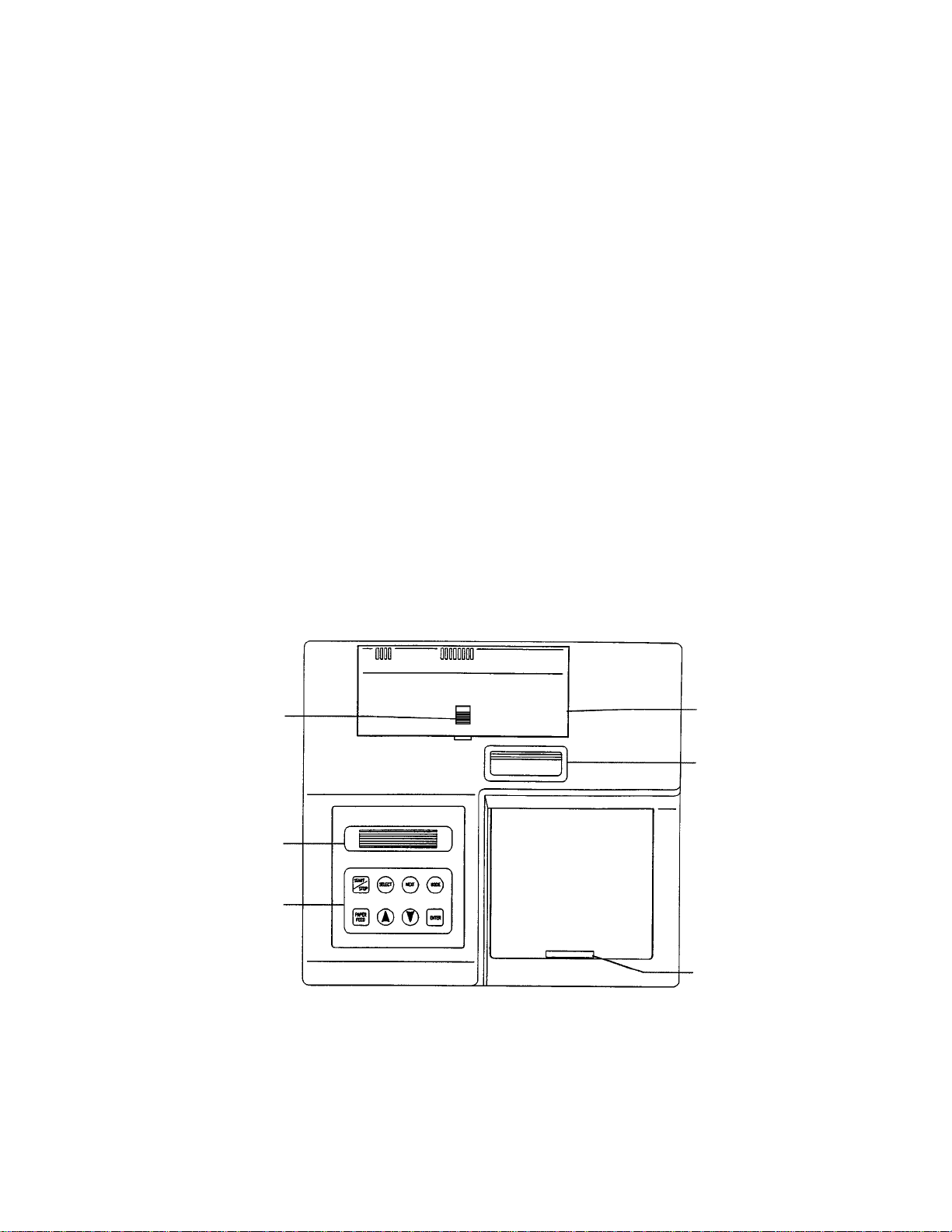
Fig. 1. Top View
2
1. Printer slot
2. Rear cover
3. Release latch for rear cover
4. Liquid crystal display (LCD)
5. Membrane keypad
6. Reading chamber door
3
4
2
1
6
5
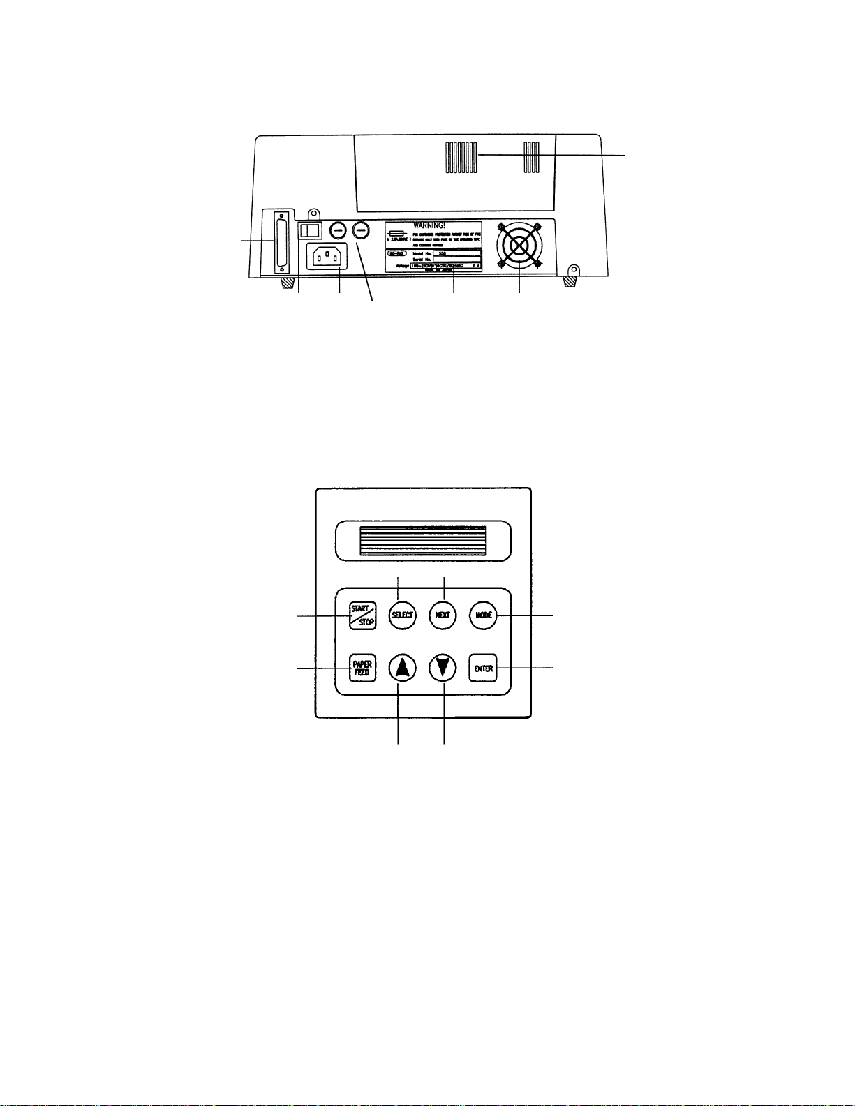
Fig. 2. Rear View
2.3 Membrane Keypad
Fig. 3. Keypad
1. START/STOP Initiates plate reading using current analysis mode. Stops plate reading.
2. PAPER FEED Advances paper strip in thermal printer.
3. UP ARROW Decreases by one the number on the cursor position or moves a cursor
to the preceding mode.
4. DOWN ARROW Increases by one the cursor position or moves a cursor to the next mode.
5. ENTER Completes or seals a field entry.
6. MODE Enables ARROW keys to change modes.
7. NEXT Moves the cursor to the next field.
8. SELECT Toggles a yes/no switch. If the check box is empty, the feature is turned
off. If the check box is black, the feature is turned on.
3
7. RS-232 serial interface
8. ON/OFF switch
9. Power cord receptacle
10. Fuses
11. Serial Number Label
12. Cooling Fan
13. Cooling Vents
13
1211
10
9
8
8
3
4
1
2
6
5
7
7

Section 3
Instrument Set-up
3.1 Initial Start-up
1. Place the instrument on a clean, sturdy table or bench. It is important to keep the instru-
ment in a clean, relatively dust free environment to ensure maximum performance.
2. Connect the power cord to the back of the instrument. Before connecting the instrument
to the main electrical supply, check that the AC voltage is appropriate for the instrument.
3. Turn on the power switch on the rear panel. The LCD will display the version number of
the on-board firmware. After about three seconds, the instrument will perform an initial
self diagnosis that requires about one minute. Allow three minutes for the instrument to
warm up (reach thermal equilibrium) before reading plates.
4. Install the printer paper. The thermal printer paper is treated on one side only, and must
be properly installed for the printer to function. The side of the paper that faces out from
the roll is the treated side.
a. Open the rear cover of the instrument.
b. Tear off a small piece of the beginning of the roll on a diagonal to form a point.
c. Place the roll of paper in the small pan-like holder positioned below the printer.
The roll should be positioned so that it will feed from the bottom.
d.While pressing the PAPER FEED key, feed the pointed end of the paper into the
paper feed slot in the underside of the printer until the printer grabs the paper and
feeds it through the slot in the top of the instrument.
e. Securely close the rear compartment.
Section 4
Operation
4.1 Overview
The Model 550 Microplate Reader has built-in software that allows the user to set the
locations of assay blanks, select assay filter(s), set the values of the analysis limits, and select
the report types to be printed. The software communicates through the two-line, 16-character LCD and is controlled through the instrument’s membrane keypad.
The display shows the current mode of the on-board software. The software has eight
different modes: the PLATE READING mode, in which data are collected, and seven modes
for setting the reading and reporting parameters. The user presses the MODE key to toggle
between collecting data in the PLATE READING mode and setting parameters in one of the
seven other modes. The modes used to set parameters are: PRINT REPORTS, SET ANALYSIS, SET REPORT TYPES, SET BLANKS, SET LIMITS, SET CUTOFF and SET CONCENTRATION. If the MODE key is pressed when the instrument is in the PLATE
READING mode, the instrument will switch into the PRINT REPORT mode. The user may
then step through the other six parameter-setting modes by pressing either ARROW key.
When the desired mode is displayed in the LCD, the user presses the ENTER key in order to
modify the mode parameters.
4

In general, the on-board software is operated by:
* Pressing MODE and the ARROW keys until the desired mode is displayed.
* Pressing the ARROW keys to choose the parameter to change.
* Pressing SELECT to toggle amoung choices.
* Pressing ENTER to seal the user’s selection.
Calculations
The Microplate Reader uses Beer’s Law to calculate the absorbance value of each well.
Beer’s Law states that absorbance is equal to the log10of the ratio of the baseline measurement
intensity (Io) to the sample measurement intensity (I).
Beer’s Law
Absorbance = Log10(Io/I)
Before measuring the plate, the reader takes a reading for all eight photodiode channels.
These values are recorded as the baseline measurement (Io) values for each channel, respectively. The reader then records the sample measurement (I) value for each well, and calculates
the absorbance using these values. Channel-to-channel error is significantly reduced because
the Io value for a given channel is used only in determining the absorbance of the wells of that
channel. (The Io values are not averaged.)
Memory Back-up
The battery back-up provides memory even after the plate reader is turned off. The following information will be saved in the memory until a new plate is read by the instrument.
Note that if reading a new plate is aborted before it is finished, all the previous data remain
in memory and none of the data from the new plate are retained.
1. Last plate reading data (absorbances for all 96 wells)
2. Reading mode
a. Single or dual wavelength
b.Measurement filter position
c. Reference filter position
d.Plate mixing Yes/No
3. Report types selected
4. Blank well locations
5. Limit values
6. Cutoff report parameters
a. Report type (Constant or Formula)
b.Cutoff constant value
c. Control well locations for formula cutoff
7. Concentration report parameters
a. Number of samples and sample replicates
b.Standard concentration values
c. Number of standards and standard replicates
5

The first time the instrument is turned on, or after a battery failure, the following default
information will be held in the memory.
1. 96 absorbance values of 0.000
2. Dual wavelength reading
3. Measurement filter position is #1 and Reference filter position is #2
4. Plate mixing is inactive (No)
5. Raw data report is selected, all other types are deselected
6. No blank wells are assigned
7. Upper limit is 3.500 and the Lower limit is 0.000
8. The constant type of cutoff report is selected
9. Constant cutoff value is 0.000
10. Concentration report parameters
a. # STDs = 0
b.# Samples = 0
c. Replicate STDs = 1
d.Replicate Samples = 1
e. All STD concentrations = 0.000
Limits
The microplate reader displays absorbance readings with absolute values as high as 3.500.
Out-of-range absorbance values, i.e. those with absolute values greater than 3.500, are displayed as either ‘*.***’ or ‘-*.***’. For example if the absorbance is 4.500, then the display
will read ‘*.***’, and if the absorbance is -4.500, the display will read ‘-*.***’.
Reports
Six types of reports can be generated by the Microplate Reader: Raw, Absorbance, Matrix,
Limit, Cutoff and Concentration.
A. The RAW DATA REPORT is the uncorrected absorbance values (without blank
subtraction). In single-wavelength mode, the reported value is the measured
absorbance. In dual-wavelength mode, the reported value is the difference between
the uncorrected readings taken with the measurement filter and with the reference filter.
B. The ABSORBANCE REPORT is the blank-corrected absorbance values. The mean
absorbance value of all of the wells designated as assay blanks is calculated and then
subtracted from all 96 values of the raw data set to produce the Absorbance Report.
Abs = Raw - mean
mean = ∑ X / n
S.D. = [ {∑ X2- n*(mean)2} / {n - 1} ]
1/2
where mean = Blank mean
S.D. = Standard deviation
∑ X = Sum total of the raw absorbances for each blank
∑ X2= Sum total of the squared raw absorbances for each blank
n = Number of blanks
6

Notes:
1. If an out-of-range absorbance is measured in one of the blank wells,
then the report will show:
Blank mean *.***
Std. Dev. *.***
If the out-of-range value is below -3.500, then the asterisks will be
preceded by a negative sign (-).
2. If the number of blanks is zero, then the report will show:
Blank mean 0.000
Std. Dev. 0.000
3. If the number of blanks is one, the report will show:
Blank mean Raw absorbance value of the one blank well
Std. Dev. 0.000
C. The MATRIX REPORT provides a qualitative report of the relative magnitude of
the absorbances on the plate. The absorbance range defined by the upper and lower
limits (set as described in Section 4.3, Set Limit Mode) is divided into 10 equal partitions, numbered 0 through 9. The blank-subtracted absorbance value of each well is
classified according to the partition of the matrix to which it corresponds, and is
reported as a single digit. Wells with absorbances greater then the upper limit are represented by plus signs (+), and wells with absorbances less then the lower limit by
minus signs (-).
D. The LIMIT REPORT provides a qualitative YES/NO report. Wells with blank-
subtracted absorbances between the upper and lower limits are represented with an
asterisk (*), wells with absorbances below the lower limit by minus signs (-), and
wells with absorbances greater then the upper limit by positive signs (+).
E. The CUTOFF REPORT provides a qualitative score for each well compared to a
cutoff value. If the absorbance of a well is within 10% (i.e., +/-10%) of the cutoff
value, the well is scored ‘+/-’. If the absorbance of a well is more than 10% greater
than the cutoff value, the well is scored ‘+’, and if the absorbance of a well is more
than 10% below the cutoff value, the well is scored ‘-’.
The cutoff value may be assigned by either the CONSTANT method or the FORMULA method. In the constant method, the user inputs an absorbance value to be used
as the cutoff, e.g. 1.000 O.D. By this example, all wells with absorbances between 0.9
and 1.1 will be scored ‘+/-’, all wells below 0.900 will be scored ‘-’ and all wells
above 1.100 will be scored ‘+’.
When the formula method is chosen, the user prepares both posititve and negative
controls. As many as eight sets of controls may be chosen. The mean absorbances
and standard deviations are calculated and reported for both sets of controls, and
then a cutoff value is calculated by the formula:
Cutoff value = Mean of negative controls + 0.10 * Mean of the positive controls
Consider an example in which the mean absorbance of the negative controls is 0.200
and the mean absorbance of the positive controls is 1.000. The calculated cutoff
value will be 0.300 (cutoff = 0.200 + 0.10 * 1.000) and wells with absorbances
between 0.270 and 0.330 will be scored ‘+/-’, wells with absorbances less than 0.270
or greater than 0.330 will be scored ‘-’ or ‘+’, respectively.
7

Notes:
1. If one of the positive or negative control wells has an out-of-range absorbance
value, the values reported for positive and negative mean and standard deviation will be asterisks. If the out-ot-range value is below -3.500, then the asterisks will be preceded by a minus sign (-). For example, the report may show
Pos. Mean *.***
Pos. Dev. *.***
Neg. Mean *.***
Neg. Dev. *.***
Cutoff 1.234
2. If the calculated cutoff value is greater than 3.500 or less than
-3.500,then the report will show
Cutoff *.***
or
Cutoff -*.***
3. If the number of standards is zero for the formula method, then the report
will show the positive and negative means and standard deviations as 0.000.
4. If the number of standards is one in the formula method, then the positive
control mean and the negative control mean will be the absorbance val
ues of the one positive control and the one negative control, respectively,
and the reported standard deviations will be 0.000.
5. If the calculated cutoff value is 0.000, then all readings greater than 0.000
are reported as ‘+’, all negative readings are reported as ‘-’, and all 0.000
readings reported as ‘+/-’.
F. The CONCENTRATION REPORT lists the absorbances of the samples and thencal-
culates concentrations of the samples based on the absorbances of a series of standards.
The on-board software calculates the best fit straight line between each set of two consecutive data points in the standard curve of absorbance vs. concen-tration. When there
is only one standard, a line is drawn between the data point and the origin to create a standard curve. When there is more than one standard, the ori-gin is not considered a data
point. Because of the way in which standard curves are calculated, standard data must be
input in either ascending or descending order (see Section 4.3, Set Concentration Mode).
Consider the case when there are four standards. The software makes a plot of
absorbance vs. concentration and then calculates the three equations (Eq1, Eq2 and
Eq3) which describe the straight lines that join (1) the first (Conc1, Abs1) and second
(Conc2, Abs2) standard data points, (2) the second and third (Conc3, Abs3) standard
data points, and (3) the third and fourth (Conc4, Abs4) standard data points. The
equation used by the software to calculate the sample concentration depends on the
absorbance of the sample. If the sample absorbance is less than Abs1, the software
extrapolates Eq1, the line determined by standard data points 1 and 2. The same
equation is used to determine the unknown concentration when the absorbance of
the unknown is between Abs1 and Abs2. However, Eq2 is used to determine the
concentration of unknowns with absorbances between Abs2 and Abs3, and Eq3 is
used to determine the concentration of all samples with absorbances greater than Abs3.
There are six pre-determined microplate formats associated with the concentration report.
The assignment of the template is made by the software based on (1) the maximum
number of samples, which may be set at 40, 44, 80 or 88; (2) the number of standards,
which range from zero to seven; (3) the number of sample replicates, one or two and (4)
the number of standard replicates, also one or two. The six different formats are shown
in the figures below. Format information is summarized in the following table.
8
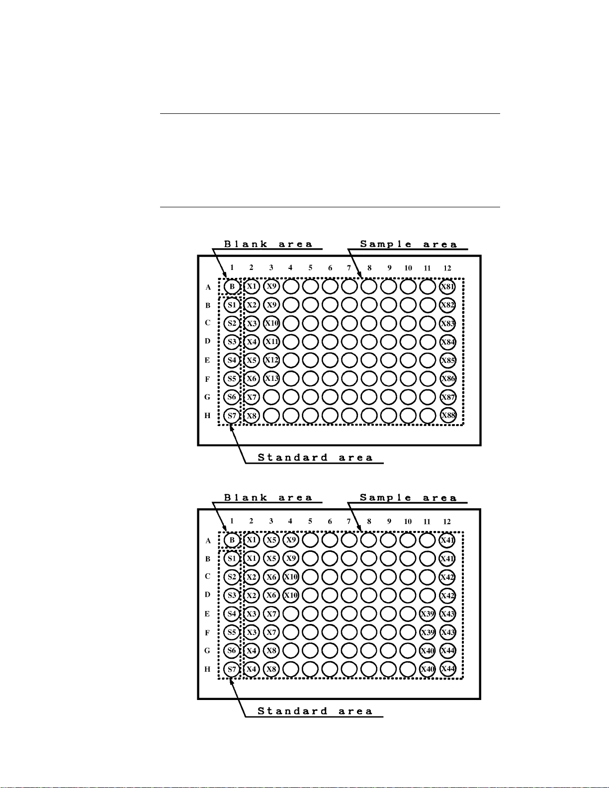
Format No. 1:
Format No. 2:
9
Stored No. of Standard Sample Max. No.
Plate Format Standards Replicates Replicates Samples
No. 1 0–7 1 1 88
No. 2 0–7 1 2 44
No. 3 0–3 2 1 88
No. 4 0–3 2 2 44
No. 5 0–7 2 1 80
No. 6 0–7 2 2 40
 Loading...