


ROG Strix Z370-F Gaming
Table of contents
 Loading...
ROG
STRIX Z370-F
GAMING
Motherboard

E13351
First Edition
August 2017
Copyright© 2017 ASUSTeK COMPUTER INC. All Rights Reserved.
No part of this manual, including the products and software described in it, may be reproduced,
transmitted, transcribed, stored in a retrieval system, or translated into any language in any form or by any
means, except documentation kept by the purchaser for backup purposes, without the express written
permission of ASUSTeK COMPUTER INC. (“ASUS”).
Product warranty or service will not be extended if: (1) the product is repaired, modied or altered, unless
such repair, modication of alteration is authorized in writing by ASUS; or (2) the serial number of the
product is defaced or missing.
ASUS PROVIDES THIS MANUAL “AS IS” WITHOUT WARRANTY OF ANY KIND, EITHER EXPRESS
OR IMPLIED, INCLUDING BUT NOT LIMITED TO THE IMPLIED WARRANTIES OR CONDITIONS OF
MERCHANTABILITY OR FITNESS FOR A PARTICULAR PURPOSE. IN NO EVENT SHALL ASUS, ITS
DIRECTORS, OFFICERS, EMPLOYEES OR AGENTS BE LIABLE FOR ANY INDIRECT, SPECIAL,
INCIDENTAL, OR CONSEQUENTIAL DAMAGES (INCLUDING DAMAGES FOR LOSS OF PROFITS,
LOSS OF BUSINESS, LOSS OF USE OR DATA, INTERRUPTION OF BUSINESS AND THE LIKE),
EVEN IF ASUS HAS BEEN ADVISED OF THE POSSIBILITY OF SUCH DAMAGES ARISING FROM ANY
DEFECT OR ERROR IN THIS MANUAL OR PRODUCT.
SPECIFICATIONS AND INFORMATION CONTAINED IN THIS MANUAL ARE FURNISHED FOR
INFORMATIONAL USE ONLY, AND ARE SUBJECT TO CHANGE AT ANY TIME WITHOUT NOTICE,
AND SHOULD NOT BE CONSTRUED AS A COMMITMENT BY ASUS. ASUS ASSUMES NO
RESPONSIBILITY OR LIABILITY FOR ANY ERRORS OR INACCURACIES THAT MAY APPEAR IN THIS
MANUAL, INCLUDING THE PRODUCTS AND SOFTWARE DESCRIBED IN IT.
Products and corporate names appearing in this manual may or may not be registered trademarks or
copyrights of their respective companies, and are used only for identication or explanation and to the
owners’ benet, without intent to infringe.
Offer to Provide Source Code of Certain Software
This product contains copyrighted software that is licensed under the General Public License (“GPL”),
under the Lesser General Public License Version (“LGPL”) and/or other Free Open Source Software
Licenses. Such software in this product is distributed without any warranty to the extent permitted by the
applicable law. Copies of these licenses are included in this product.
Where the applicable license entitles you to the source code of such software and/or other additional data,
you may obtain it for a period of three years after our last shipment of the product, either
(1) for free by downloading it from https://www.asus.com/support/
or
(2) for the cost of reproduction and shipment, which is dependent on the preferred carrier and the location
where you want to have it shipped to, by sending a request to:
ASUSTeK Computer Inc.
Legal Compliance Dept.
15 Li Te Rd.,
Beitou, Taipei 112
Taiwan
In your request please provide the name, model number and version, as stated in the About Box of the
product for which you wish to obtain the corresponding source code and your contact details so that we
can coordinate the terms and cost of shipment with you.
The source code will be distributed WITHOUT ANY WARRANTY and licensed under the same license as
the corresponding binary/object code.
This offer is valid to anyone in receipt of this information.
ASUSTeK is eager to duly provide complete source code as required under various Free Open Source
Software licenses. If however you encounter any problems in obtaining the full corresponding source
code we would be much obliged if you give us a notication to the email address gpl@asus.com, stating
the product and describing the problem (please DO NOT send large attachments such as source code
archives, etc. to this email address).
ii

Contents
Safety information ...................................................................................................... vi
About this guide ........................................................................................................ vii
ROG STRIX Z370-F GAMING specications summary ........................................... ix
Package contents ..................................................................................................... xiii
Installation tools and components ......................................................................... xiv
Chapter 1: Product Introduction
1.1 Motherboard overview ............................................................................... 1-1
1.1.1 Before you proceed .....................................................................1-1
1.1.2 Motherboard layout .....................................................................1-2
1.1.3 Central Processing Unit (CPU) ...................................................1-4
1.1.4 System memory ..........................................................................1-5
1.1.5 Expansion slots ...........................................................................1-7
1.1.6 Jumpers and holes ......................................................................1-9
1.1.7 Onboard LEDs ..........................................................................1-11
1.1.8 Internal connectors....................................................................1-12
Chapter 2: Basic Installation
2.1 Building your PC system...........................................................................2-1
2.1.1 Motherboard installation ..............................................................2-1
2.1.2 CPU installation...........................................................................2-3
2.1.3 CPU heatsink and fan assembly installation ............................... 2-5
2.1.4 DIMM installation.........................................................................2-7
2.1.5 ATX power connection ................................................................2-8
2.1.6 SATA device connection .............................................................2-9
2.1.7 Front I/O connector ...................................................................2-10
2.1.8 Expansion card installation .......................................................2-11
2.1.9 M.2 installation ..........................................................................2-13
2.1.10 Fan holder installation ............................................................... 2-15
2.2 Motherboard rear and audio connections ............................................. 2-16
2.2.1 Rear I/O connection ..................................................................2-16
2.2.2 Audio I/O connections ...............................................................2-18
2.3 Starting up for the rst time .................................................................... 2-20
2.4 Turning off the computer ........................................................................ 2-21
iii

Chapter 3: BIOS Setup
3.1 Knowing BIOS ............................................................................................ 3-1
3.2 BIOS setup program .................................................................................. 3-2
3.2.1 EZ Mode......................................................................................3-3
3.2.2 Advanced Mode ..........................................................................3-4
3.2.3 QFan Control...............................................................................3-7
3.2.4 EZ Tuning Wizard .......................................................................3-9
3.3 My Favorites ............................................................................................. 3-12
3.4 Main menu ................................................................................................ 3-14
3.5 Ai Tweaker menu......................................................................................3-14
3.6 Advanced menu ....................................................................................... 3-16
3.6.1 Platform Misc Conguration ......................................................3-16
3.6.2 CPU Conguration ....................................................................3-16
3.6.3 System Agent (SA) Conguration .............................................3-17
3.6.4 PCH Conguration ....................................................................3-17
3.6.5 PCH Storage Conguration.......................................................3-17
3.6.6 PCH-FW Conguration .............................................................3-18
3.6.7 Onboard Devices Conguration ................................................3-18
3.6.8 APM Conguration ....................................................................3-19
3.6.9 Network Stack Conguration.....................................................3-19
3.6.10 HDD/SSD SMART Information ................................................. 3-19
3.6.11 USB Conguration .................................................................... 3-19
3.7 Monitor menu ........................................................................................... 3-20
3.8 Boot menu ................................................................................................ 3-20
3.9 Tool menu ................................................................................................. 3-22
3.9.1 ASUS EZ Flash 3 Utility ............................................................3-22
3.9.2 Secure Erase ............................................................................3-22
3.9.3 ASUS Overclocking Prole .......................................................3-24
3.9.4 ASUS SPD Information .............................................................3-24
3.9.5 Graphics Card Information ........................................................3-24
3.10 Exit menu .................................................................................................. 3-25
3.11 Updating BIOS .......................................................................................... 3-25
3.11.1 EZ Update ................................................................................. 3-25
3.11.2 ASUS EZ Flash 3 ...................................................................... 3-26
3.11.3 ASUS CrashFree BIOS 3 .......................................................... 3-28
iv

Chapter 4: RAID Support
4.1 RAID congurations .................................................................................. 4-1
4.1.1 RAID denitions ..........................................................................4-1
4.1.2 Installing Serial ATA hard disks ..................................................4-2
4.1.3 Intel® Rapid Storage Technology in UEFI BIOS .......................... 4-2
4.1.4 Intel® Rapid Storage Technology Option ROM utility .................. 4-6
4.2 Creating a RAID driver disk.....................................................................4-10
4.2.1 Creating a RAID driver disk in Windows® ................................. 4-10
Appendix
Notices .................................................................................................................... A-1
ASUS contact information ...................................................................................... A-5
v

Safety information
Electrical safety
• To prevent electrical shock hazard, disconnect the power cable from the electrical outlet
before relocating the system.
• When adding or removing devices to or from the system, ensure that the power cables
for the devices are unplugged before the signal cables are connected. If possible,
disconnect all power cables from the existing system before you add a device.
• Before connecting or removing signal cables from the motherboard, ensure that all
power cables are unplugged.
• Seek professional assistance before using an adapter or extension cord. These devices
could interrupt the grounding circuit.
• Ensure that your power supply is set to the correct voltage in your area. If you are not
sure about the voltage of the electrical outlet you are using, contact your local power
company.
• If the power supply is broken, do not try to x it by yourself. Contact a qualied service
technician or your retailer.
Operation safety
• Before installing the motherboard and adding devices on it, carefully read all the manuals
that came with the package.
• Before using the product, ensure all cables are correctly connected and the power
cables are not damaged. If you detect any damage, contact your dealer immediately.
• To avoid short circuits, keep paper clips, screws, and staples away from connectors,
slots, sockets and circuitry.
• Avoid dust, humidity, and temperature extremes. Do not place the product in any area
where it may become wet.
• Place the product on a stable surface.
• If you encounter technical problems with the product, contact a qualied service
technician or your retailer.
vi

About this guide
This user guide contains the information you need when installing and conguring the
motherboard.
How this guide is organized
This guide contains the following parts:
1. Chapter 1: Product Introduction
This chapter describes the features of the motherboard and the new technology it
supports. It includes description of the switches, jumpers, and connectors on the
motherboard.
2. Chapter 2: Basic Installation
This chapter lists the hardware setup procedures that you have to perform when
installing system components.
3. Chapter 3: BIOS Setup
This chapter tells how to change system settings through the BIOS Setup menus.
Detailed descriptions of the BIOS parameters are also provided.
4. Chapter 4: RAID Support
This chapter describes the RAID congurations.
Where to nd more information
Refer to the following sources for additional information and for product and software
updates.
1. ASUS website
The ASUS website (www.asus.com) provides updated information on ASUS hardware
and software products.
2. Optional documentation
Your product package may include optional documentation, such as warranty yers,
that may have been added by your dealer. These documents are not part of the
standard package.
vii
Conventions used in this guide
To ensure that you perform certain tasks properly, take note of the following symbols used
throughout this manual.
DANGER/WARNING: Information to prevent injury to yourself when trying to
complete a task.
CAUTION: Information to prevent damage to the components when trying to
complete a task.
IMPORTANT: Instructions that you MUST follow to complete a task.
NOTE: Tips and additional information to help you complete a task.
Typography
Bold text
Italics
<Key>
<Key1> + <Key2> + <Key3>
Indicates a menu or an item to select.
Used to emphasize a word or a phrase.
Keys enclosed in the less-than and greater-than sign
means that you must press the enclosed key.
Example: <Enter> means that you must press the Enter or
Return key.
If you must press two or more keys simultaneously, the key
names are linked with a plus sign (+).
viii

ROG STRIX Z370-F GAMING specications summary
Intel® Socket 1151 for 8th Generation Core™ Processors
Supports 14nm CPU
CPU
Chipset
Memory
Expansion slots
VGA
Multi-GPU
support
Rear Panel I/O
Ports
Supports Intel® Turbo Boost Technology 2.0*
* The support of these features depends on the CPU types.
** Refer to www.asus.com for Intel® CPU support list.
Intel® Z370 Chipset
4 x DIMM, max. 64GB DDR4 4000(OC)* / 3866(OC)* / 3733(OC)* /
3600(OC)* / 3466(OC)* / 3400(OC)* / 3333(OC)* / 3300(OC)* /
3200(OC)* / 3000(OC)* / 2800(OC)* / 2666 / 2400 / 2133 MHz non-ECC,
un-buffered memory
Dual channel memory architecture
Supports Intel® Extreme Memory Prole (XMP)*
* Hyper DIMM support is subject to the physical characteristics of individual CPUs.
Please refer to Memory QVL(Qualied Vendors List) for details.
2 x PCIe 3.0/2.0 x16 slots (supports x16, x8/x8, x8/x4+x4*, x8+x4+x4/x0**)
1 x PCIe 3.0/2.0 x16 slot (max. at x4 mode)
4 x PCIe 3.0/2.0 x1 slots
* For 2 Intel® SSDs on CPU support, install a Hyper M.2 X16 card (sold separately)
into the PCIeX8_2 slot, and enable this card under BIOS settings.
** For 3 Intel® SSDs on CPU support, install a Hyper M.2 X16 card (sold separately)
into the PCIeX16/x8_1 slot, and enable this card under BIOS settings.
Integrated Graphics Processor- Intel® HD Graphics support
Multi-VGA output support: DisplayPort/HDMI/DVI-D ports
Supports DisplayPort 1.2* with max. resolution 4096 x 2304@60Hz
Supports HDMI 1.4b with max. resolution 4096 x 2160@24Hz
Supports DVI-D with max. resolution 1920 x 1200@60Hz
Supports Intel® InTru™ 3D/Quick Sync Video/Clear Video HD Technology/
Insider™
Supports up to 3 displays simultaneously
Maximum shared memory of 1024MB
* DP 1.2 Multi-Stream Transport compliant, supports DP 1.2 monitor daisy chain
up to 3 displays
Supports NVIDIA® 2-Way SLI™ Technology
Supports AMD® 3-Way CrossFireX™ Technology
2 x USB3.1 Gen2 ports (1 x Type-A [red] and 1 x Type-C ports at back
panel)
1 x DVI port
1 x HDMI port
1 x DP port
2 x USB 3.1 Gen1 ports [blue]
2 x USB 2.0 ports
1 x Anti-surge LAN (RJ45) port
5 x Audio jacks
1 x Optical S/PDIF out
(continued on the next page)
ix

ROG STRIX Z370-F GAMING specications summary
Intel® Z370 Chipset with RAID 0, 1, 5, 10 and Intel Rapid Storage
Technology support
- 6 x SATA 6Gb/s ports
- 1 x M.2_1 Socket 3 with M key, type 2242/2260/2280 storage devices
support (both SATA & PCIE 3.0 x 4 modes)*
- 1 x M.2_2 Socket 3 with M key, type 2242/2260/2280 storage devices
support (PCIE 3.0 x 4 mode)**
Storage
Audio
USB
LAN
- Ready for Intel® Optane Memory***
* The M.2_1 socket shares SATA_1 port when use M.2 SATA mode device. Adjust
BIOS settings to use a SATA device.
** The M.2_2 socket shares SATA_56 ports when use M.2 PCIE mode device in X4
mode. Adjust BIOS settings to use SATA devices.
*** Intel® Optane Technology only supported when using 8th Generation Intel®
Processors. Before using Intel® Optane memory modules, ensure that you have
updated your motherboard drivers and BIOS to the latest version from ASUS
support website.
ROG SupremeFX S1220A 8-Channel High Denition Audio CODEC
- Supports up to 32-Bit/192kHz playback*
- Impedance sense for front and rear headphone outputs
- High quality 120dB SNR stereo playback output and 113 dB SNR
recording input
- SupremeFX Shielding Technology
- Dual Headphone Ampliers
- Jack-detection, Multi-streaming, and Front Panel Jack-retasking
- Optical S/PDIF out port at back panel
Audio Features:
- Sonic Radar III
- Sonic Studio III + Sonic Studio Link
* Due to limitations in HDA bandwidth, 32-Bit/192kHz is not supported for
8-Channel audio.
Intel® Z370 Chipset:
- 6 x USB 3.1 Gen1 ports ( 2 ports at back panel [blue], 4 ports at midboard)
- 6 x USB 2.0 ports ( 2 ports at back panel, 4 ports at mid-board)
ASMedia® USB 3.1 controllers*:
- 2 x USB 3.1 Gen2 ports (1 x Type-A [red] and 1 x Type-C at back panel)
* Supports 3A power output
Intel® I219-V Gigabit LAN- Dual interconnect between the integrated Media
Access Controller (MAC) and physical layer (PHY)
Anti-surge LANGuard
ROG GameFirst Technology
(continued on the next page)
x

ROG STRIX Z370-F GAMING specications summary
ROG RAMCache II
ROG Exclusive
Features
ASUS Special
Features
ROG GameFirst IV
ROG CPU-Z
ROG Overwolf
ROG CloneDrive
Performance Optimization
5-Way Optimization
- Whole system optimization with a single click! Perfectly consolidates
better CPU performance, power saving, digital power control, system
cooling and app usages.
Digi+VRM
EPU
- EPU
TPU
- Auto Tuning, TPU, GPU Boost
Fan Xpert 4 featuring Fan Auto Tuning function and multiple
thermistors selection for optimized system cooling control
ASUS EZ DIY
- ASUS CrashFree BIOS 3
- ASUS EZ Flash 3
ASUS Q-Design
- Q-Shield
- Q-LED (CPU, DRAM, VGA, Boot Device LED)
- Q-Slot
- Q-DIMM
Gamer’s Guardian
- SafeSlot
- DIGI+ VRM
- DRAM Overcurrent Protection
- ESD Guards on LAN, Audio, and USB ports
- Highly Durable Components
- Stainless Steel Back I/O
ASUS Exclusive Features
- AURA Lighting Control
- 3D Printing Friendly Design
- AI Suite 3
- AI Charger
(continued on the next page)
xi
ROG STRIX Z370-F GAMING specications summary
2 x USB 3.1 Gen1 connectors support additional 4 x USB 3.1 Gen1 ports
2 x USB 2.0 connectors support additional 4 x USB 2.0 ports
6 x SATA 6Gb/s connectors
1 x 4-Pin M.2_FAN connector
1 x 4-Pin AIO_PUMP fan connector
1 x 4-Pin CPU fan connector
1 x 4-Pin CPU_OPT fan connector
2 x 4-Pin Chassis fan connectors
1 x 5-Pin Extension fan connector
1 x 24-pin EATX power connector
Internal I/O
connectors
BIOS Features
Manageability
Support DVD
contents
Operating
system support
Form factor
1 x 8-pin EATX 12V power connector
1 x M.2_1 Socket 3 for M Key, type 2242/2260/2280 storage devices support
( Supports PCIE and SATA modes)
1 x M.2_2 Socket 3 for M Key, type 2242/2260/2280 storage devices support
(Supports PCIE mode only)
1 x Front panel audio connector (AAFP)
1 x COM connector
2 x RGB headers
1 x Addressable header
1 x TPM connector
1 x System panel connector
1 x Thermal sensor connector
1 x CPU_OV
1 x Clear CMOS jumper (2-pin)
128 Mb Flash ROM, UEFI AMI BIOS, PnP, WfM2.0, SM BIOS 3.0, ACPI
6.0, Multi-language BIOS, ASUS EZ Flash 3, CrashFree BIOS 3, F11 EZ
Tuning Wizard, F6 Qfan Control, F3 My Favorites, Last Modied log, F12
PrintScreen and ASUS DRAM SPD (Serial Presence Detect) memory
information
WfM2.0, DMI3.0, WOL by PME, PXE
Drivers
ASUS Utilities
EZ Update
Anti-virus software (OEM version)
Windows® 10 64-bit
ATX Form Factor, 12”x 9.6” (30.5cm x 24.4cm)
Specications are subject to change without notice. Please refer to the ASUS website for
the latest specications.
xii

Package contents
Check your motherboard package for the following items.
Motherboard ROG STRIX Z370-F GAMING
4 x SATA 6Gb/s cables
1 x SLI HB BRIDGE (2-WAY-M)
Cables
Accessories
Application drive ROG motherboard support DVD
Documentation User guide
If any of the above items is damaged or missing, contact your retailer.
1 x RGB LED extension cable
1 x Addressable LED extension cable
1 x Thermal sensor cable
1 x I/O shield
1 x CPU Installation tool
1 x STRIX series sticker
1 x 3D Printing Mount
1 x M.2 screw package
1 x CPU fan holder
1 x Pack of cable ties
1 x ROG STRIX Door hanger
xiii
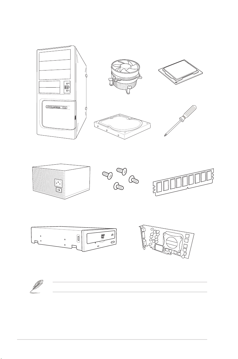
Installation tools and components
Intel® 1151 compatible CPU Fan
Intel® 1151 CPU
PC chassis
Power supply unit
SATA optical disc drive (optional)
SATA hard disk drive
1 bag of screws
Phillips (cross) screwdriver
DIMM
Graphics card
The tools and components listed above are not included in the motherboard package.
xiv

Chapter 1: Product Introduction
Product Introduction
1
1.1 Motherboard overview
1.1.1 Before you proceed
Take note of the following precautions before you install motherboard components or change
any motherboard settings.
• Unplug the power cord from the wall socket before touching any component.
• Before handling components, use a grounded wrist strap or touch a safely grounded
object or a metal object, such as the power supply case, to avoid damaging them due
to static electricity.
• Hold components by the edges to avoid touching the ICs on them.
• Whenever you uninstall any component, place it on a grounded antistatic pad or in the
bag that came with the component.
• Before you install or remove any component, ensure that the ATX power supply is
switched off or the power cord is detached from the power supply. Failure to do so
may cause severe damage to the motherboard, peripherals, or components.
Chapter 1
ASUS ROG STRIX Z370-F GAMING
1-1
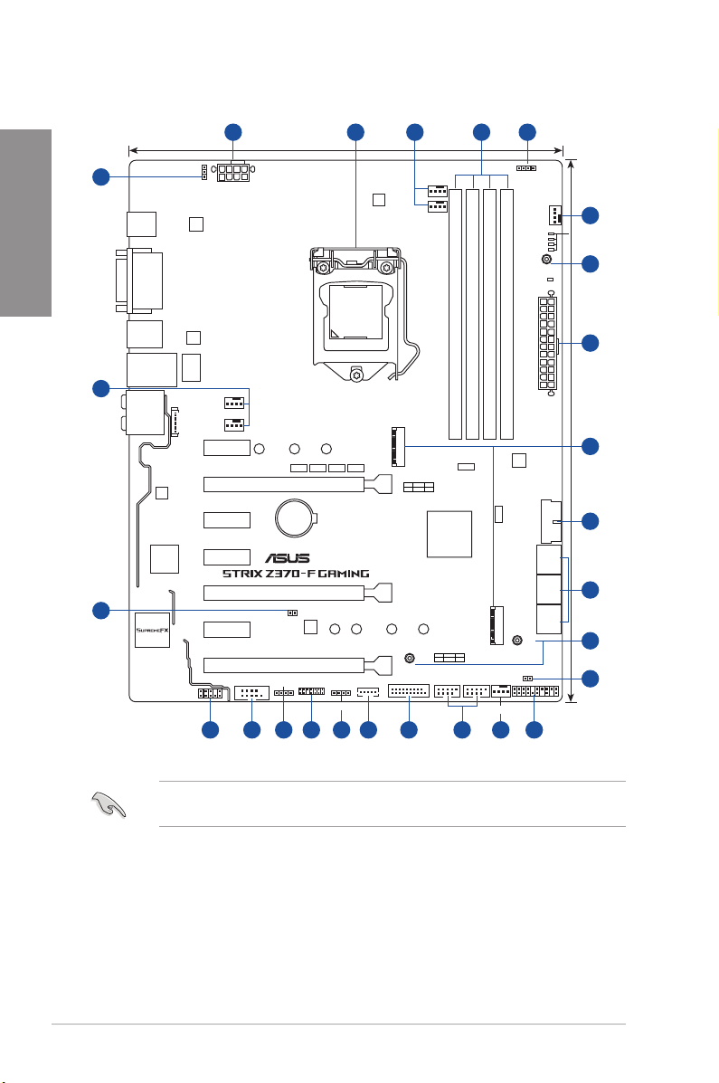
1.1.2 Motherboard layout
Chapter 1
18
3
17
USB31G2_EC1
USB31G2_E2
DP
DVI
HDMI
USB1314
LAN1_U31G1_56
AUDIO
WGI
219V
Super
1 42 53
CPU_OV
EATX12V
ASM
3142
24.4cm(9.6in)
CPU_FAN
DIGI+
EPU
CPU_OPT
RGB_HEADER2
PWR_LED
CHA_FAN1
3D
MOUNT
3
BOOT_DEVICE_LED
VGA_LED
DRAM_LED
CPU_LED
6
LGA1151
ASM
1442K
DDR4 DIMM_B1 (64bit, 288-pin module)
DDR4 DIMM_B2 (64bit, 288-pin module)
DDR4 DIMM_A1 (64bit, 288-pin module)
LANGuard
CHA_FAN2
AIO_PUMP
CON_BACKIO
PCIE_X1_1
2280 2260 2242
ASM1480 ASM1480 ASM1480 ASM1480
PCIE_X16/X8_1
Lithium Cell
PCIE_X1_2
PCIE_X1_3
I/O
CMOS Power
®
M.2_2(SOCKET3)
M.2_2(SOCKET3)
PCIE SATA IRST
X4XV
Intel
Z370
DDR4 DIMM_A2 (64bit, 288-pin module)
ASM
ASM1480
®
3142
ASM1480
PCIE_X8_2
3D
MOUNT
U31G1_34
M.2_1(SOCKET3)
M.2_1(SOCKET3)
PCIE SATA IRST
X4VV
USB910 USB1112
M.2_FAN
PANEL
MOUNT
CLRTC
3D
1131451516
T_SENSOR1
PCIE_X1_4
TPU
2280 2260 2242
PCIE_X4
COM
AAFP
RGB_HEADER1
TPM
EXT_FAN
ADD_HEADER
313 8 12
EATXPWR
SATA6G_1
SATA6G_3
SATA6G_5
U31G1_12
SATA6G_2
SATA6G_4
SATA6G_6
1
30.5cm(12in)
7
8
9
6
10
1-2
Refer to 1.1.8 Internal connectors and 2.2.1 Rear I/O connection for more information
about rear panel connectors and internal connectors.
Chapter 1: Product Introduction

Layout contents
Connectors/Jumpers/Buttons and switches/Slots Page
1. ATX power connectors (24-pin EATXPWR; 8-pin EATX12V) 1-16
2. LGA1151 CPU socket 1-4
3. CPU, CPU optional, AIO pump, M.2, extension, and chassis fan
connectors (4-pin CPU_FAN; 4-pin CPU_OPT; 4-pin AIO_PUMP; 4-pin
M.2_FAN; 5-pin EXT_FAN; 4-pin CHA_FAN1-2)
4. DDR4 DIMM slots 1-5
5. RGB headers (4-pin RGB_HEADER1-2) 1-19
6. 3D Mount 1-10
7. M.2 sockets (M.2_1; M.2_2) 1-20
8. USB 3.1 Gen1 connectors (20-1 pin U31G1_12,U31G1_34) 1-13
9. Intel® Serial ATA 6 Gb/s connectors (7-pin SATA6G_12, SATA 6G_34,
SATA 6G_56)
10. Clear RTC RAM jumper (2-pin CLRTC) 1-9
11. System panel connector (20-3 pin PANEL) 1-17
12. USB 2.0 connectors (10-1 pin USB910, USB1112) 1-14
13. Addressable RGB header (4-1 pin ADD_HEADER)
14. TPM connector (14-1 pin TPM) 1-18
15. Serial port connector (10-1 pin COM) 1-14
16. Front panel audio connector (10-1 pin AAFP) 1-13
17. Thermal sensor cable connector (2-pin T_SENSOR) 1-18
18. CPU over voltage jumper (3-pin CPU_OV) 1-10
1-15
Chapter 1
1-12
1-21
ASUS ROG STRIX Z370-F GAMING
1-3
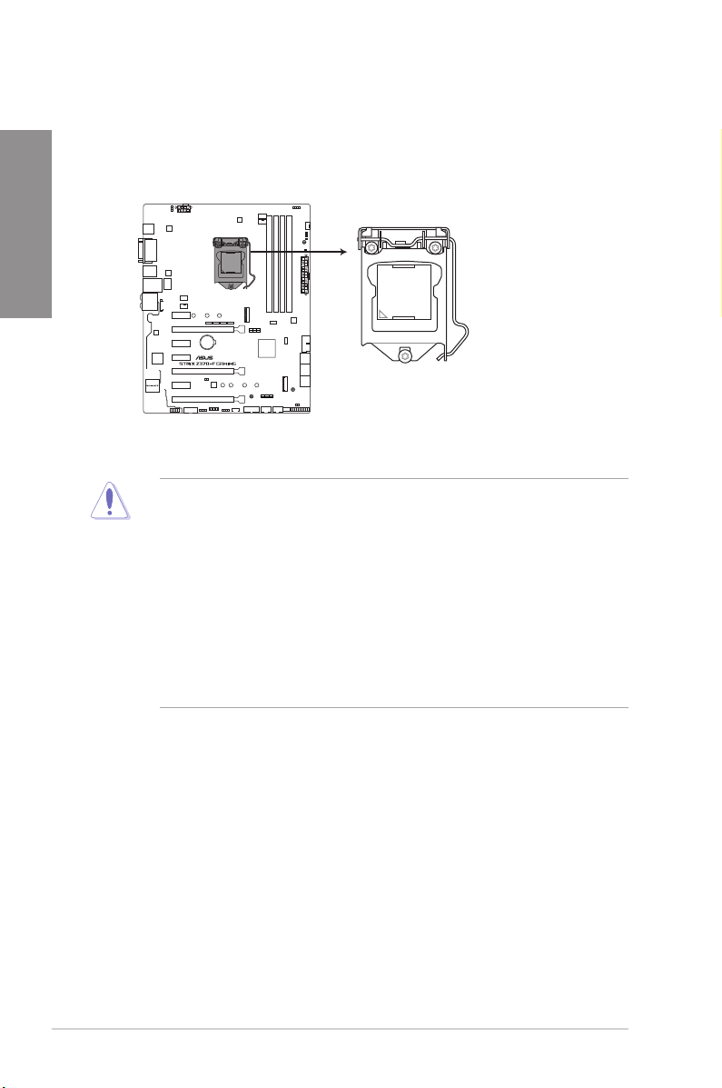
1.1.3 Central Processing Unit (CPU)
ROG STRIX Z370-F GAMING CPU LGA1151
The motherboard comes with a surface mount LGA1151 socket designed for the 8th
Generation Intel® Core™ processors.
Chapter 1
®
• Ensure that all power cables are unplugged before installing the CPU.
• Upon purchase of the motherboard, ensure that the PnP cap is on the socket and
the socket contacts are not bent. Contact your retailer immediately if the PnP cap
is missing, or if you see any damage to the PnP cap/socket contacts/motherboard
components. ASUS will shoulder the cost of repair only if the damage is shipment/
transit-related.
• Keep the cap after installing the motherboard. ASUS will process Return Merchandise
Authorization (RMA) requests only if the motherboard comes with the cap on the
LGA1151 socket.
• The product warranty does not cover damage to the socket contacts resulting from
incorrect CPU installation/removal, or misplacement/loss/incorrect removal of the PnP
cap.
1-4
Chapter 1: Product Introduction
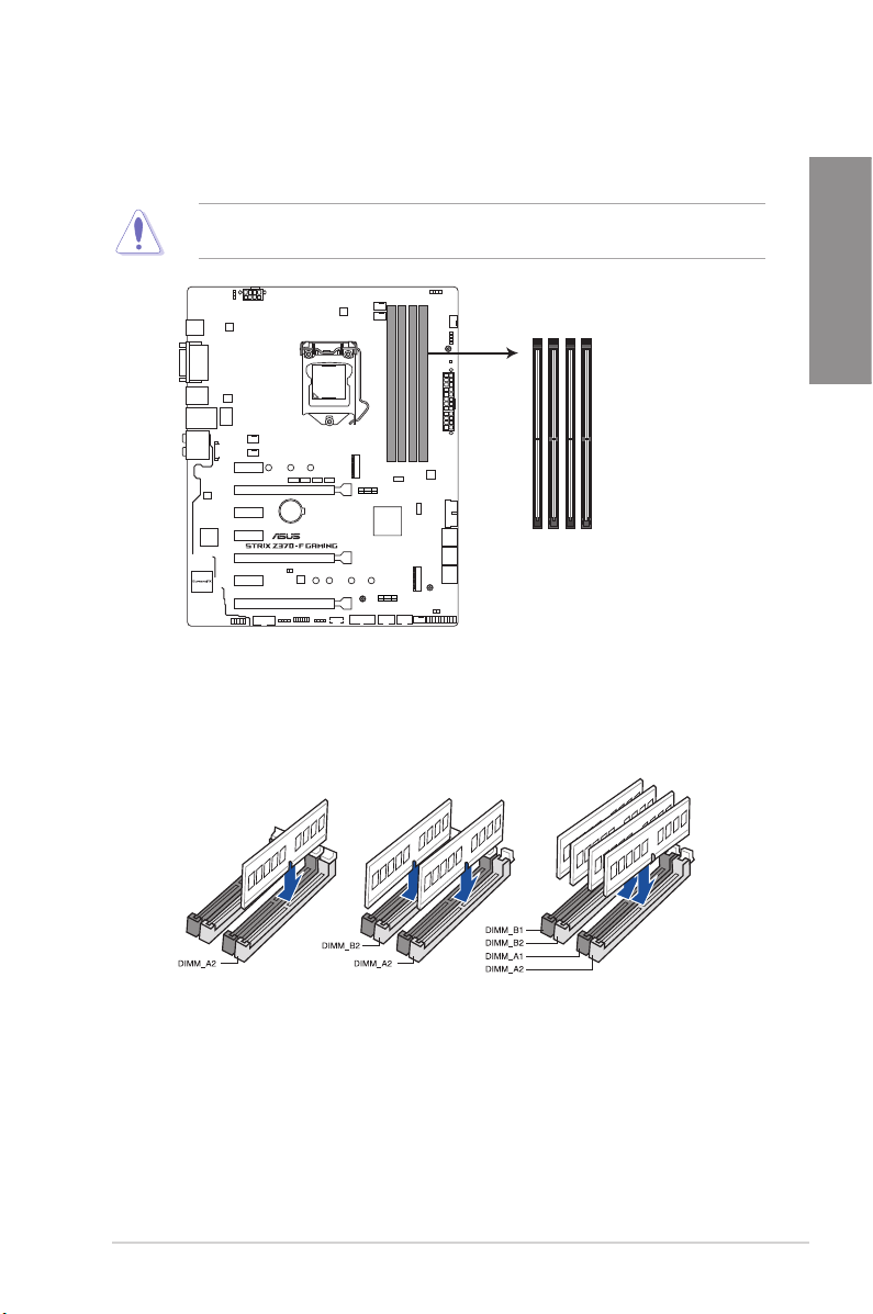
1.1.4 System memory
The motherboard comes with four DDR4 (Double Data Rate 4) Quad Inline Memory Modules
(DIMM) slots.
A DDR4 module is notched differently from a DDR, DDR2, or DDR3 module. DO NOT
install a DDR, DDR2, or DDR3 memory module to the DDR4 slot.
DIMM_B1
DIMM_B2
DIMM_A1
DIMM_A2
®
ROG STRIX Z370-F GAMING
288-pin DDR4 DIMM sockets
Recommended memory congurations
Chapter 1
ASUS ROG STRIX Z370-F GAMING
1-5

Memory congurations
You may install 1 GB, 2 GB, 4 GB, 8 GB and 16 GB unbuffered and non-ECC DDR4 DIMMs
into the DIMM sockets.
Chapter 1
• You may install varying memory sizes in Channel A, and Channel B. The system
maps the total size of the lower-sized channel for the dual-channel conguration. Any
excess memory from the higher-sized channel is then mapped for single-channel
operation.
• Due to the memory address limitation on 32-bit Windows® OS, when you install 4GB
or more memory on the motherboard, the actual usable memory for the OS can be
about 3GB or less. For effective use of memory, we recommend that you do any of the
following:
a) Use a maximum of 3GB system memory if you are using a 32-bit Windows® OS.
b) Install a 64-bit Windows® OS when you want to install 4 GB or more on the
motherboard.
c) For more details, refer to the Microsoft® support site at http://support.microsoft.
com/kb/929605/en-us.
• The design of the DIMM fan may vary. Ensure that the DIMM fan ts to the
motherboard
• The default memory operation frequency is dependent on its Serial Presence Detect
(SPD), which is the standard way of accessing information from a memory module.
Under the default state, some memory modules for overclocking may operate at a
lower frequency than the vendor-marked value.
• For system stability, use a more efcient memory cooling system to support a full
memory load (4 DIMMs) or overclocking condition.
• Memory modules with memory frequency higher than 2133MHz and their
corresponding timing or the loaded XMP prole is not the JEDEC memory standard.
The stability and compatibility of the memory modules depend on the CPU’s
capabilities and other installed devices.
• Always install the DIMMS with the same CAS Latency. For an optimum compatibility,
we recommend that you install memory modules of the same version or data code
(D/C) from the same vendor. Check with the vendor to get the correct memory
modules.
• ASUS exclusively provides hyper DIMM support function.
• Hyper DIMM support is subject to the physical characteristics of individual CPUs. Load
the X.M.P. or D.O.C.P. settings in the BIOS for the hyper DIMM support.
• Visit the ASUS website for the latest QVL.
1-6
Chapter 1: Product Introduction
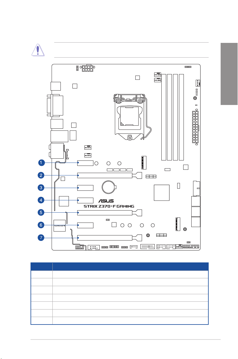
1.1.5 Expansion slots
Unplug the power cord before adding or removing expansion cards. Failure to do so may
cause you physical injury and damage motherboard components.
PCIE_X1_1
PCIE_X16/X8_1
PCIE_X1_2
Chapter 1
PCIE_X1_3
PCIE_X8_2
PCIE_X1_4
PCIE_X4
Slot No. Slot Description
1 PCIE_x1_1 slot
2 PCIE_x16/x8_1 slot
3 PCIE_x1_2 slot
4 PCIE_x1_3 slot
5 PCIE_x8_2 slot
6 PCIE_x1_4 slot
7 PCIE_x4 slot
ASUS ROG STRIX Z370-F GAMING
®
1-7
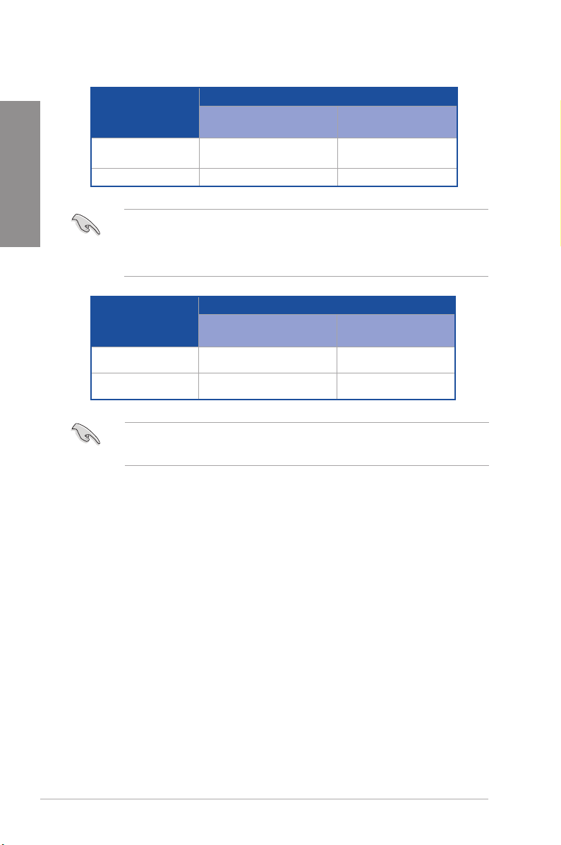
Chapter 1
Single VGA/PCIe card
Dual VGA/PCIe cards x8 x8
PCI Express 3.0 operating mode
VGA conguration
• We recommend that you provide sufcient power when running CrossFireX™ or SLI™
mode.
• Connect a chassis fan to the motherboard connector labeled CHA_FAN1-2 when
using multiple graphics cards for better thermal environment.
PCIe_x16/x8_1 PCIe_x8_2
x16 (single VGA
recommended)
N/A
Hyper M.2 X16 card
conguration
2 Intel® SSDs on CPU
support
3 Intel® SSDs on CPU
support
• Hyper M.2 X16 card is purchased separately.
• Enable the Hyper M.2 X16 card under BIOS settings.
PCI Express 3.0 operating mode
PCIe_x16/x8_1 PCIe_x8_2
x8 x4+x4
x8+x4+x4 N/A
1-8
Chapter 1: Product Introduction
1.1.6 Jumpers and holes
1. Clear RTC RAM jumper (2-pin CLRTC)
This jumper allows you to clear the Real Time Clock (RTC) RAM in CMOS. You can
clear the CMOS memory of date, time, and system setup parameters by erasing the
CMOS RTC RAM data. The onboard button cell battery powers the RAM data in
CMOS, which include system setup information such as system passwords.
Chapter 1
®
ROG STRIX Z370-F GAMING Clear RTC RAM
CLRTC
PIN 1
+3V_BAT
GND
To erase the RTC RAM:
1. Turn OFF the computer and unplug the power cord.
2. Short-circuit pin 1-2 with a metal object or jumper cap for about 5-10 seconds.
3. Plug the power cord and turn ON the computer.
4. Hold down the <Delete> key during the boot process and enter BIOS setup to re-enter
data.
Except when clearing the RTC RAM, never remove the cap on CLRTC jumper default
position. Removing the cap will cause system boot failure!
• If the steps above do not help, remove the onboard battery and move the jumper
again to clear the CMOS RTC RAM data. After the CMOS clearance, reinstall the
battery.
• You do not need to clear the RTC when the system hangs due to overclocking. For
system failure due to overclocking, use the C.P.R. (CPU Parameter Recall) feature.
Shut down and reboot the system so the BIOS can automatically reset parameter
settings to default values.
• Due to the chipset behavior, AC power off is required to enable C.P.R. function. You
must turn off and on the power supply or unplug and plug the power cord before
rebooting the system.
ASUS ROG STRIX Z370-F GAMING
1-9
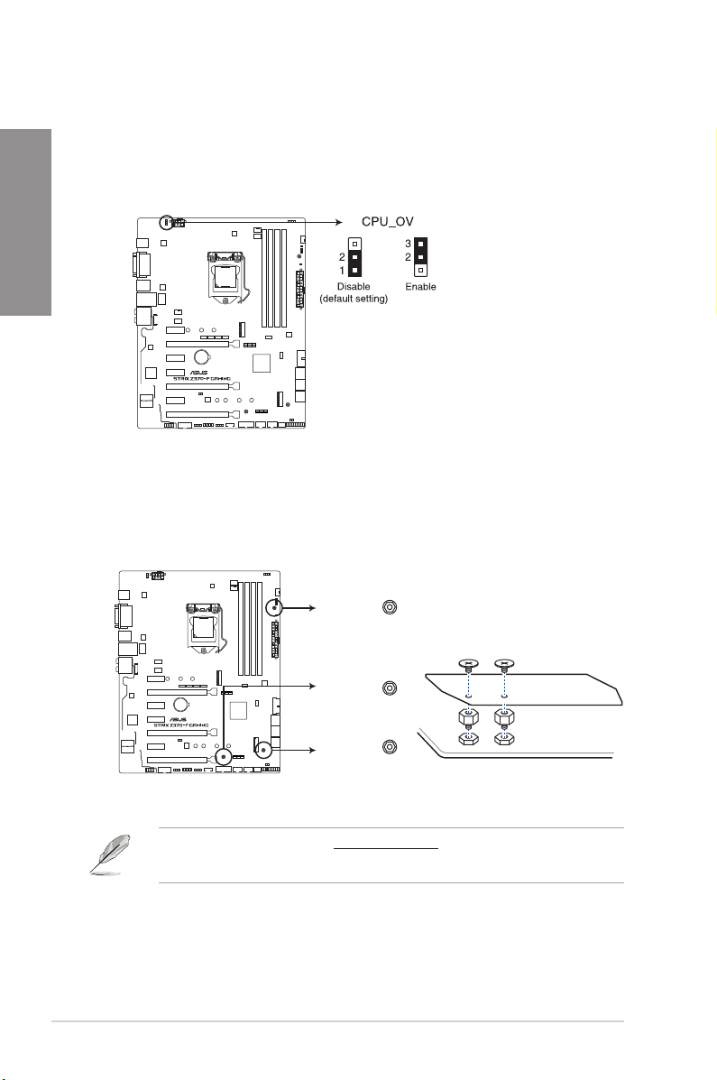
2. CPU over voltage jumper (3-pin CPU_OV)
The CPU over voltage jumper allows you to set a higher CPU voltage for a exible
overclocking system, depending on the type of the installed CPU. To gain more CPU
Chapter 1
voltage setting, insert the jumper to pins 2-3. To go back to its default CPU voltage
setting, insert the jumper to pins 1-2.
3. 3D Mount
Secure 3D printed parts to these 3D Mount holes for a personalized motherboard.
®
ROG STRIX Z370-F GAMING CPU_OV setting
3D Mount
1-10
3D Mount
®
3D Mount
ROG STRIX Z370-F GAMING 3D Printing Mount
• Download 3D source les at http://www.asus.com.
• Use the bundled 3D Mount screws to install the 3D printed parts.
Chapter 1: Product Introduction
1.1.7 Onboard LEDs
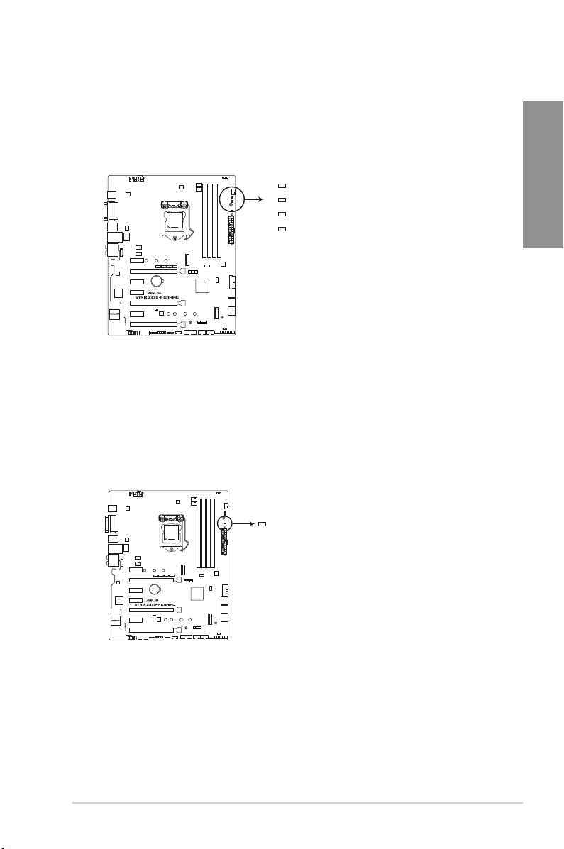
1. POST State LEDs
The POST State LEDs provide the status of these key components during POST
(Power-On Self-Test): CPU, memory modules, VGA card, and hard disk drives. If an
error is found, the critical component’s LED stays lit up until the problem is solved.
BOOT (YELLOW GREEN)
VGA (WHITE)
DRAM (YELLOW)
CPU (RED)
®
ROG STRIX Z370-F GAMING
CPU/DRAM/BOOT_DEVICE/VGA LED
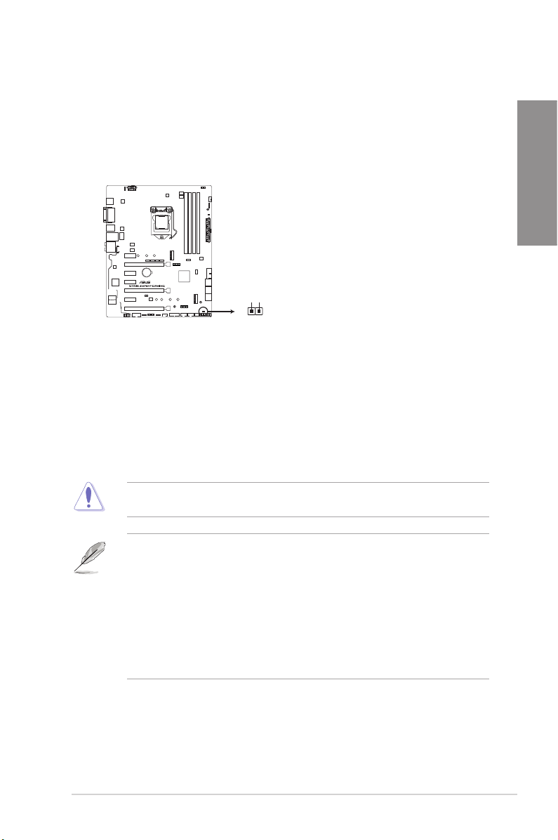
2. Standby Power LED
The motherboard comes with a standby power LED. The LED lights up to indicate that
the system is ON, in sleep mode, or in soft-off mode. This is a reminder that you should
shut down the system and unplug the power cable before removing or plugging in any
motherboard component. The illustration below shows the location of the onboard LED.
Chapter 1
®
ROG STRIX Z370-F GAMING PWR_LED
ASUS ROG STRIX Z370-F GAMING
PWR_LED
1-11

1.1.8 Internal connectors
1. Intel® Serial ATA 6 Gb/s connectors (7-pin SATA6G_12, SATA 6G_34, SATA
Chapter 1
6G_56)
These connectors connect to Serial ATA 6 Gb/s hard disk drives via Serial ATA 6 Gb/s
signal cables.
If you installed Serial ATA hard disk drives, you can create a RAID 0, 1, 5, and 10
conguration with the Intel® Rapid Storage Technology through the onboard Intel®
Z370 chipset.
SATA6G_1
GND
RSATA_TXP1
RSATA_TXN1
GND
RSATA_RXN1
RSATA_RXP1
GND
SATA6G_3
GND
RSATA_TXP3
RSATA_TXN3
GND
RSATA_RXN3
RSATA_RXP3
GND
®
SATA6G_5
RSATA_TXP5
RSATA_TXN5
RSATA_RXN5
RSATA_RXP5
GND
GND
GND
SATA6G_2
RSATA_TXP2
RSATA_TXN2
RSATA_RXN2
RSATA_RXP2
SATA6G_4
RSATA_TXP4
RSATA_TXN4
RSATA_RXN4
RSATA_RXP4
SATA6G_6
RSATA_TXP6
RSATA_TXN6
RSATA_RXN6
RSATA_RXP6
GND
GND
GND
GND
GND
GND
GND
GND
GND
ROG STRIX Z370-F GAMING Intel® SATA 6 Gb/s connectors
• These connectors are set to [AHCI] by default. If you intend to create a Serial ATA
RAID set using these connectors, set the SATA Mode item in the BIOS to [Intel RST
Premium With Intel Optane System Acceleration (RAID)].
• Before creating a RAID set, refer to the manual bundled in the motherboard support
DVD.
1-12
Chapter 1: Product Introduction
2. Front panel audio connector (10-1 pin AAFP)
This connector is for a chassis-mounted front panel audio I/O module that supports HD
Audio. Connect one end of the front panel audio I/O module cable to this connector.
AGNDNCSENSE1_RETUR
SENSE2_RETUR
AAFP
Chapter 1
®
PORT1 L
PORT1 R
PORT2 R
SENSE_SEND
HD-audio-compliant
pin definition
PORT2 L
ROG STRIX Z370-F GAMING Analog front panel connector
We recommend that you connect a high-denition front panel audio module to this
connector to avail of the motherboard’s high-denition audio capability.
4. USB 3.1 Gen1 connectors (20-1 pin U31G1_12, U31G1_34)
These connectors allow you to connect a USB 3.1 Gen1 module for additional USB 3.1
Gen1 front or rear panel ports. With an installed USB 3.1 Gen1 module, you can enjoy
all the benets of USB 3.1 Gen1 including faster data transfer speeds of up to 5 Gb/s,
faster charging time for USB-chargeable devices, optimized power efciency, and
backward compatibility with USB 2.0.
A
U31G1_12
Vbus
IntA_P1_SSRX-
IntA_P1_SSRX+
GND
IntA_P1_SSTX-
IntA_P1_SSTX+
Vbus
IntA_P2_SSRX-
IntA_P2_SSRX+
GND
GND
IntA_P2_SSTX-
IntA_P2_SSTX+
PIN 1
A
®
B
IntA_P1_D-
IntA_P1_D+
GND
GND
IntA_P2_D-
IntA_P2_D+
B
U31G1_34
IntA_P2_D+
IntA_P2_D-
GND
IntA_P2_SSTX+
GND
GND
IntA_P1_D-
IntA_P1_D+
IntA_P2_SSTX-
GND
IntA_P2_SSRX+
IntA_P2_SSRX-
Vbus
GND
IntA_P1_SSTX-
IntA_P1_SSRX-
IntA_P1_SSTX+
IntA_P1_SSRX+
PIN 1
Vbus
ROG STRIX Z370-F GAMING USB 3.1 Gen1 connectors
The USB 3.1 Gen1 module is purchased separately.
ASUS ROG STRIX Z370-F GAMING
1-13
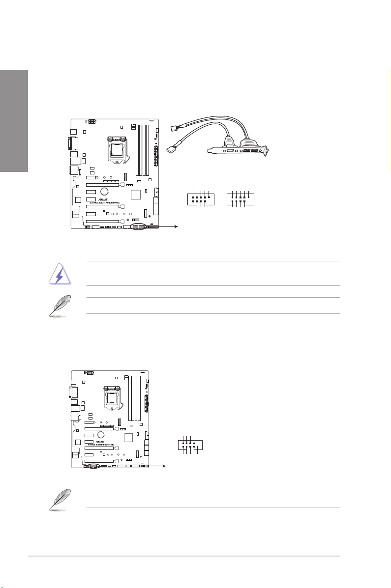
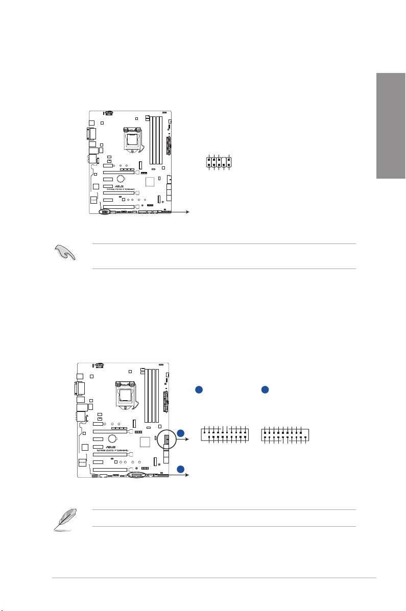
5. USB 2.0 connectors (10-1 pin USB910, USB1112)
These connectors are for USB 2.0 ports. Connect the USB module cable to these
connectors, then install the module to a slot opening at the back of the system chassis.
Chapter 1
This USB connector complies with USB 2.0 specication that supports up to 480 Mb/s
connection speed.
USB910
USB+5V
®
USB_P10-
PIN 1
USB+5V
USB_P9-
USB_P10+
GND
NC
GND
USB_P9+
USB1112
PIN 1
USB+5V
USB_P12-
USB+5V
USB_P11-
USB_P12+
GND
NC
GND
USB_P11+
ROG STRIX Z370-F GAMING USB2.0 connector
DO NOT connect a 1394 cable to the USB connectors. Doing so will damage the
motherboard!
The USB 2.0 module is purchased separately.
6. Serial port connector (10-1 pin COM)
This connector is for a serial (COM) port. Connect the serial port module cable to this
connector, then install the module to a slot opening at the back of the system chassis.
RXD1
DTR1
DSR1
®
COM
ROG STRIX Z370-F GAMING Serial port connector
CTS1
PIN 1
PI1#
GND
TXD1
DCD1
RTS1#
1-14
The COM module is purchased separately.
Chapter 1: Product Introduction
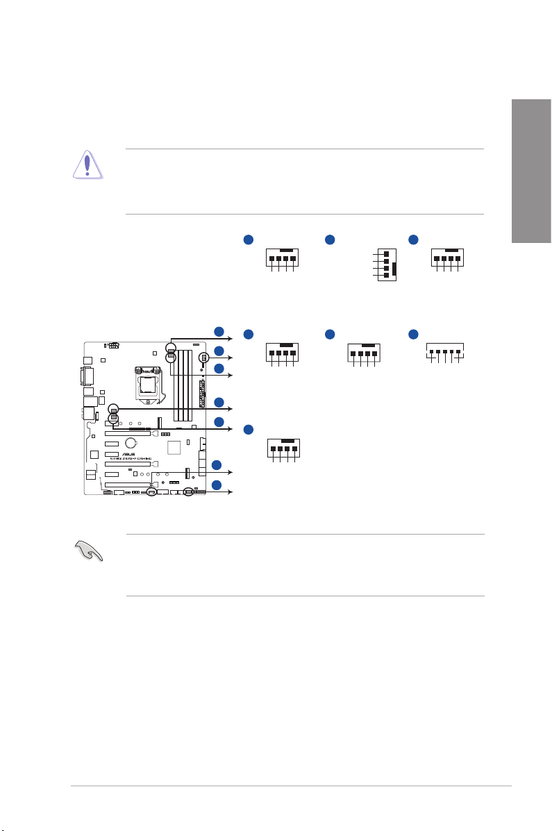
7. CPU, CPU optional, AIO pump, M.2, extension, and chassis fan connectors (4-pin
CPU_FAN; 4-pin CPU_OPT; 4-pin AIO_PUMP; 4-pin M.2_FAN; 5-pin EXT_FAN;
4-pin CHA_FAN1-2)
Connect the fan cables to the fan connectors on the motherboard, ensuring that the
black wire of each cable matches the ground pin of the connector.
• DO NOT forget to connect the fan cables to the fan connectors. Insufcient air ow
inside the system may damage the motherboard components. These are not jumpers!
Do not place jumper caps on the fan connectors!
• Ensure that the CPU fan cable is securely installed to the CPU fan connector.
Chapter 1
A
CPU_FAN
CPU FAN IN
CPU FAN PWR
A
B
C
D
E
®
F
G
CPU FAN PWM
D
CHA_FAN2
CHA FAN PWM
G
M.2_FAN
M.2 PWM
CHA FAN IN
CHA FAN PWR
M.2 IN
M.2 PWR
ROG STRIX Z370-F GAMING Fan connectors
• The CPU_FAN connector supports the CPU fan of maximum 1A (12 W) fan power.
• The EXT_FAN connector supports 2 of 5 thermal sensor sources.
• Connect the fan of your water cooling kit to the AIO_PUMP connector.
GND
GND
GND
B
CHA_FAN1
CHA FAN PWM
CHA FAN IN
CHA FAN PWR
GND
E
AIO_PUMP
AIO PUMP PWM
C
CPU_OPT
GND
CPU FAN IN
CPU FAN PWR
CPU FAN PWM
F
EXT_FAN
GND
AIO PUMP IN
AIO PUMP PWR
GND
Control2
Control1
Sense2
Sense1
ASUS ROG STRIX Z370-F GAMING
1-15
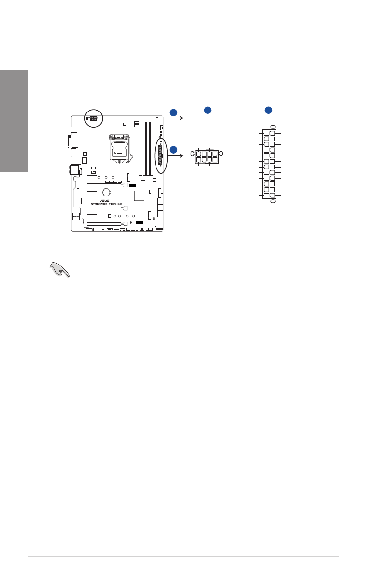
8. ATX power connectors (24-pin EATXPWR; 8-pin EATX12V)
These connectors are for ATX power supply plugs. The power supply plugs are
designed to t these connectors in only one orientation. Find the proper orientation and
Chapter 1
push down rmly until the connectors completely t.
A
B
®
A B
EATX12V
+12 Volts
+12 Volts
+12V DC
+12V DC
+12V DC
+12V DC
GND
GND
GND
PIN 1
GND
+5V Standby
Power OK
EATXPWR
+3 Volts
GND
+5 Volts
GND
+5 Volts
GND
+3 Volts
+3 Volts
GND
+5 Volts
+5 Volts
+5 Volts
-5 Volts
GND
GND
GND
PSON#
GND
-12 Volts
+3 Volts
PIN 1
ROG STRIX Z370-F GAMING ATX power connectors
• For a fully congured system, we recommend that you use a power supply unit
(PSU) that complies with ATX 12 V Specication 2.0 (or later version) and provides a
minimum power of 350 W.
• DO NOT forget to connect the 8-pin EATX12V power plug. Otherwise, the system will
not boot.
• We recommend that you use a PSU with a higher power output when conguring a
system with more power-consuming devices. The system may become unstable or
may not boot up if the power is inadequate.
• If you want to use two or more high-end PCI Express x16 cards, use a PSU with
1000W power or above to ensure the system stability.
1-16
Chapter 1: Product Introduction
Loading...