

Page 1

K
Service Source
Apple Scanners
Page 2

K
Service Source
Specifications
Apple Scanners
Page 3

Specifications Characteristics - 1
Characteristics
Scanner T ype
Maximum Document Size
Speed
Grayscale
Dropout Color
Interface
Flatbed
8.5 by 14 in.
20.4 sec. for a 300-dpi scan measuring 8.5 by 11 in.
16 levels (4 bits per pixel)
Green
SCSI
Page 4

Specifications Settings - 2
Settings
Contrast
Brightness
Threshold Values
Gray-Map
Scan Selections
Halftone Techniques
Up to 8 (specified by user)
Up to 16 (specified by user)
Up to 16 (specified by user)
More light detail, normal detail, more dark detail
Line art, halftone, grayscale
Spiral, bayer, 2 by 2, line, user-definable patterns, and adaptive
dithering to grayscale data that has been scanned.
Page 5

Specifications Electrical - 3
Electrical
Line V oltage
Frequency
120 VAC ±10%
58–62 Hz
Page 6

Specifications Physical - 4
Physical
Size
Weight
Height: 4.4 in. (11.2 cm)
Width: 13.6 in. (34.5 cm)
Depth: 21.8 in. (55.4 cm)
20 lb. (9.1 kg)
Page 7

Specifications Environmental - 5
Environmental
Operating Temperature
Storage Temperature
Relative Humidity
32–104°F (0-40°C)
–40 to 149°F (–40 to 65°C)
5–95% noncondensing
Page 8

K
Service Source
Troubleshooting
Apple Scanners
Page 9

Troubleshooting General/ - 1
General
The Symptom Charts included in this chapter will help you
diagnose specific symptoms related to your product. Because cures
are listed on the charts in the order of most likely solution, try
the first cure first. Verify whether or not the product continues to
exhibit the symptom. If the symptom persists, try the next cure.
(Note: If you have replaced a module, reinstall the original module
before you proceed to the next cure.)
If you are not sure what the problem is, or if the Symptom Charts
do not resolve the problem, refer to the Flowchart for the product
family.
For additional assistance, contact Apple Technical Support.
Page 10

Troubleshooting Symptom Charts /Miscellaneous - 2
Symptom Charts
Miscellaneous
Power lamp not on; machine dead
1 Plug in power cord.
2 Close lamp cover and turn button clockwise.
3 Check for correct setting of voltage selector (on universal
models).
4 Check interlock switch with multimeter; replace if switch is
not opening and closing.
5 Check fuses FU1, FU2, and FU3 on power supply board.
6 Check fuse 1 on logic board (4-bit only).
7 Replace logic board.
8 Replace power supply.
9 Replace transformer.
Page 11

Troubleshooting Symptom Charts /Miscellaneous - 3
Optical assembly does not move
Optical assembly moves once, then does not move
System does not boot
or locks up during
transfer of data over
SCSI bus
1 Check and clean or replace belt.
2 Check belt tension. Belt should be tight with no slack.
3 Check for damage to gears or buildup of foreign material;
clean or replace gears.
Check limit switch for continuity.
Perform “Logic Board Modification” (see Additional
Procedures).
Page 12

Troubleshooting Symptom Charts /Miscellaneous - 4
AppleScan program
crashes during
middle of scanning
operation, or
computer hangs
Fluorescent lamp won’t light or is dim
1 Verify version of AppleScan.
2 Replace power supply board.
3 Replace logic board.
1 Check lamp holder connector.
2 Check that label of fluorescent lamp faces down (into lamp
holder).
3 Replace lamp.
4 Check flexible cable.
5 Replace inverter (or optical assembly).
Page 13

Troubleshooting Symptom Charts /Miscellaneous - 5
Scan command not executed
Image not clean; dark or light spots
Scanning performed,
but image doesn’t
reach host computer
1 Check external cable connections.
2 Reset SCSI select switch on scanner to an unused device
number (factory preset at 2). Do not use 7 or 8.
3 Check that SCSI cable terminates correctly.
4 Check fuse on logic board.
5 Replace logic board.
1 Clean glass with water and soft, lint-free cloth.
2 Adjust contrast or threshold settings on application.
3 Replace lamp.
4 Replace logic board.
5 Replace optical assembly.
1 Check interface connector.
2 Replace optical assembly.
3 Check fuse on logic board.
4 Replace logic board.
Page 14

Troubleshooting Symptom Charts /Miscellaneous - 6
Incorrect image on host screen
1 Clean glass with water and soft, lint-free cloth.
2 Replace optical assembly.
Page 15

Troubleshooting Symptom Charts /Apple OneScanner for Windows - 7
Apple OneScanner for Windows
Scanner does not operate in Windows environment
1 Check connections of SCSI cable.
2 Check that SCSI terminator is installed.
3 Replace AT-to-SCSI Host Adapter card.
4 If you determine that there is a software problem, contact
the Apple Assistance Center.
Page 16

K
Service Source
T ak e Apart
Apple Scanners
Page 17
Take Apart Top Cover - 1
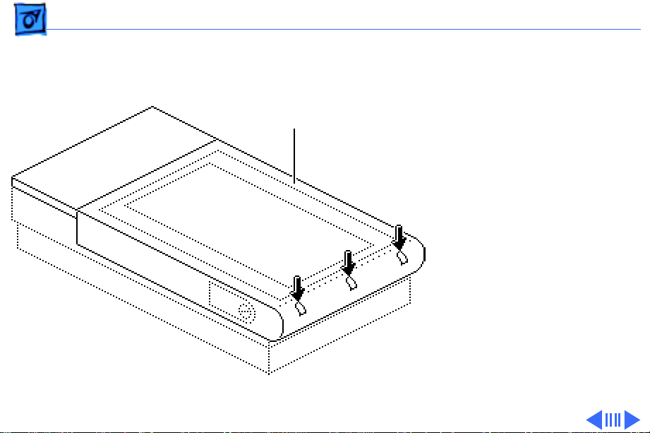
Top Cover
Top Cover
No preliminary steps are
required before you begin
this procedure.
1 Press the clips and lift
the top cover.
Page 18
Take Apart Glass Cover Assembly - 2
Glass Cover
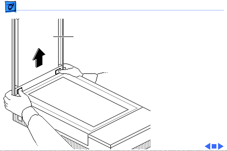
Glass Cover
Assembly
Assembly
Before you begin, remove
the top cover.
Caution:
precautions in Bulletins/
Safety.
1 Loosen the three captive
Review the ESD
screws.
Page 19
Take Apart Glass Cover Assembly - 3
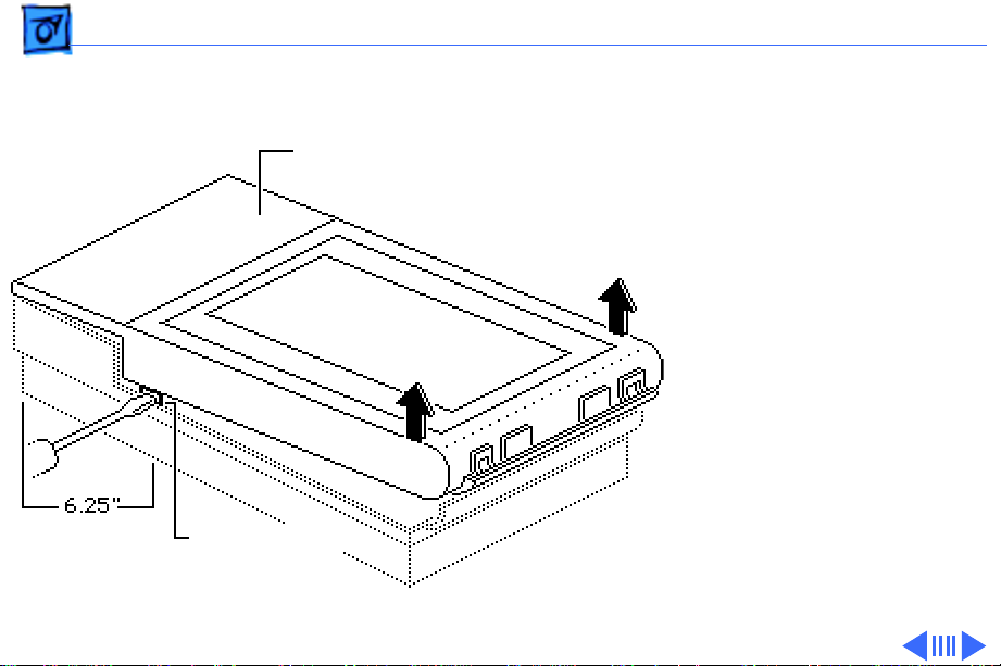
2 While lifting the glass
cover assembly from
Glass Cover Assembly
the rear, use a flatblade screwdriver to
press in and release the
two retaining clips.
Retaining Clips
(both sides)
Page 20
Take Apart Glass Cover Assembly - 4
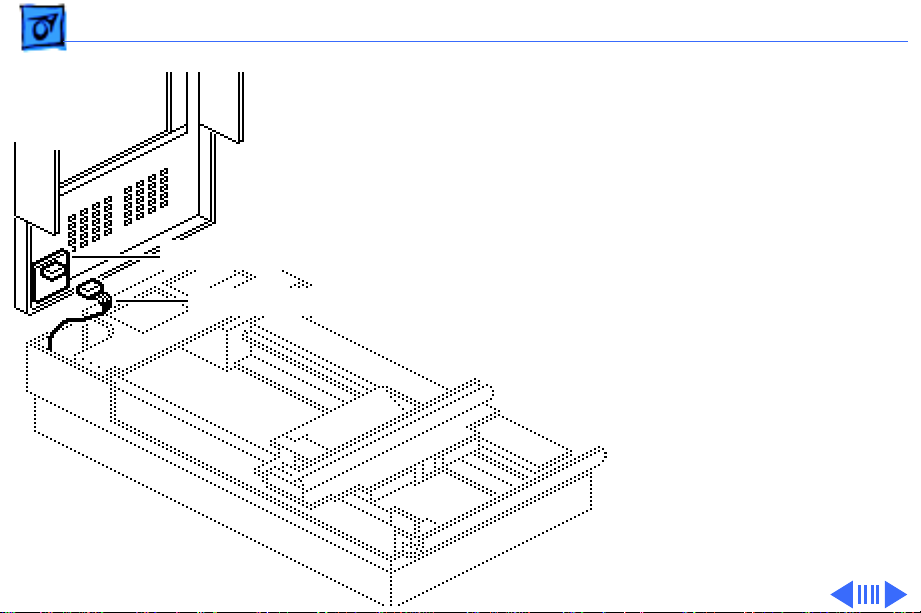
Start Scan Board
Scan Switch Cable
Caution:
Make sure that
you don’t damage the
protruding components
on the start scan board
while performing this
procedure.
3 Raise the glass cover
assembly to 90°,
disconnect the scan
switch cable from the
start scan board, and
remove the glass cover
assembly.
Page 21
Take Apart Glass Cover Assembly - 5
4
Replacement Note:
When you replace a
damaged glass cover
assembly, remove the
start scan board and
install the board on the
Start Scan Board
new glass cover
assembly.
Page 22
Take Apart Optical Assembly - 6
Optical Assembly
Before you begin, remove
Optical Assembly
the following:
• Top cover
• Glass cover assembly
Caution:
precautions in Bulletins/
Safety.
Review the ESD
Page 23
Take Apart Optical Assembly - 7
1 While pulling the wire
Retaining Screw
handle, loosen the
retaining screw and
Lamp
Assembly
remove the lamp
assembly.
Replacement Note:
Make
sure the left side of the
lamp assembly engages
the left retaining
flanges properly.
Page 24

Take Apart Optical Assembly - 8
2 Remove the two
Front Plate
retaining screws and
lift out the front plate.
Page 25

Take Apart Optical Assembly - 9
3 Push the optical
assembly to the center of
Left Guide Rail
travel and over the
cutout in the left guide
rail.
Page 26

Take Apart Optical Assembly - 10
4 Remove the two
retaining screws (and
ground strap, for 8-bit
scanner only) and slide
Ground Strap
(8-bit scanner only)
Limit Switch Assembly
the limit switch
assembly to the side.
Page 27

Take Apart Optical Assembly - 11
5 Loosen the tension lock
screw.
Pulley Lever
6 Slide the pulley lever
forward to relieve belt
tension and remove the
belt from the rear
pulley gear.
Tension Lock Screw
7 Remove the belt from the
front pulley gear.
Page 28

Take Apart Optical Assembly - 12
8 Remove the two
retaining screws and the
carrier shaft front
Front Retaining Bracket
retaining bracket.
Page 29

Take Apart Optical Assembly - 13
Optical Assembly
Caution:
Do not lift the
optical assembly too
high, or you may damage
the flex cable.
9 Lift the shaft until it
clears both support
brackets; then pull the
shaft slightly to the
right. Free the left side
of the optical assembly
from the left guide rail.
Page 30

Take Apart Optical Assembly - 14
10 Disconnect the flex
cable and remove the
cable (and ferrite bead
on the 8-bit scanner
only) from the optical
assembly.
Ferrite Bead
Flex Cable
Page 31

Take Apart Optical Assembly - 15
11 Lift the optical block
Carrier Shaft
Optical Block
from the scanner.
12 Slide the shaft out of the
optical block.
Note: Keep the carrier
stopper sleeve with the
shaft.
Page 32

Take Apart Optical Assembly - 16
13 Using a small
Retaining Clip
screwdriver, pry off
the retaining clip and
remove the belt from the
optical assembly.
Page 33

Take Apart Inverter Assembly - 17
Inverter Assembly
Before you begin, remove
the following:
• Top cover
• Glass cover assembly
Inverter Assembly
• Optical assembly
Caution:
precautions in Bulletins/
Safety.
Caution:
set screw. Loosening the
screw damages the factory
optical settings, and you
must replace the optical
assembly.
Review the ESD
Do not loosen the
Page 34

Take Apart Inverter Assembly - 18
Note:
You do not have to
remove the drive belt
from the optical block.
Drive Belt
Page 35

Take Apart Inverter Assembly - 19
1 Insert a flat-blade
screwdriver under one
side of the optical block
cover, and gently pry up
Optical Block Cover
until you hear a snap.
Perform the same
procedure on the other
side, and remove the
optical block cover.
Page 36

Take Apart Inverter Assembly - 20
Connector
Mounting
Plate
CN1
CCD Board
Inverter
Caution:
Do not loosen
the two CCD retaining
screws. Loosening the
screws damages the
optical alignment, and
you must replace the
optical assembly.
2 Disconnect connector
CN1 from the CCD board.
3 Remove the two
mounting screws and let
the inverter drop.
4 Slide the connector
mounting plate to the
left, toward the
inverter, and lift the
right side of the plate.
Page 37

Take Apart Carrier Motor - 21
Carrier Motor
Before you begin, remove
the following:
• Top cover
• Glass cover assembly
Carrier Motor
• Optical assembly
Caution:
precautions in Bulletins/
Safety.
Replacement Note:
the drive belt tensioning
spring and drive gear
pulleys now.
Review the ESD
Replace
Page 38

Take Apart Carrier Motor - 22
1 Remove the two
retaining screws and the
front inside cover.
2 Remove the three
mounting screws and the
Left Guide Rail
left guide rail.
Page 39

Take Apart Carrier Motor - 23
3 Disconnect the cable
Ground Straps
Cable Connector
connector from the
power supply Board.
4 Remove the retaining
screw and move the
ground straps out of the
way.
5 Remove the four
mounting screws and
lift out the carrier
block.
Carrier Block
Page 40

Take Apart Carrier Motor - 24
6 Remove the E-clip and
E-Clip
washer, and slide the
front gear pulley up and
off the pulley spindle.
Front Gear Pulley
7 Remove the remaining
three motor mounting
screws and the motor.
Replacement Note:
Install the motor onto
the carrier assembly
with the motor cable
facing forward.
Carrier Motor
Page 41

Take Apart Transformer - 25
Transformer
Transformer
Before you begin, remove
the following:
• Top cover
• Glass cover assembly
• Optical assembly
• Carrier block
Caution:
precautions in Bulletins/
Safety.
Review the ESD
Page 42

Take Apart Transformer - 26
AC Inlet Cover
CN5
Limit Switch Assembly
AC Switch
Cover
CN2
1 Remove the retaining
screw and slide the AC
inlet cover to the right
and out of the scanner.
2 Remove the AC switch
cover.
3 Using a small flat-blade
screwdriver, push the
retaining tab toward the
connector and disconnect
the two cable connectors,
CN2 and CN5, from the
power supply board.
4 Disconnect the cable
connector from the
limit switch assembly.
Page 43

Take Apart Transformer - 27
5 Remove the screws and
Ground Straps
ground straps.
Page 44

Take Apart Transformer - 28
6 Remove the two
remaining screws and
lift out the transformer.
Page 45

Take Apart Transformer - 29
Power Select Switch
Transformer Bracket
Transformer
7 Remove the two
mounting screws and
separate the
transformer from the
transformer bracket.
8 Remove the two
mounting screws and the
power select switch
from the transformer
bracket (on universal
transformers only).
Page 46

Take Apart Power Supply Board - 30
Power Supply Board
Power Supply Board
Before you begin, remove
the following:
• Top cover
• Glass cover assembly
• Optical assembly
Caution:
precautions in Bulletins/
Safety.
Review the ESD
Page 47

Take Apart Power Supply Board - 31
1 Remove the retaining
AC Inlet Cover
screw and slide the AC
inlet cover to the right
and out of the scanner.
AC Switch
Cover
2 Remove the AC switch
cover.
Page 48

Take Apart Power Supply Board - 32
3 Remove the three
mounting screws and the
left guide rail.
Left Guide Rail
Ground
Strap
Bracket
4 Remove the two
mounting screws and the
ground strap bracket.
Page 49

Take Apart Power Supply Board - 33
Note:
On the 8-bit
Power Supply Board
scanner, remove the
logic board (with metal
case) to allow removal of
the power cable
connector.
CN4
CN3
CN5
Ground Wire
CN2
CN1
5 Disconnect the five
cable connectors from
the power supply board:
• CN1
• CN2
• CN3
• CN4
• CN5
6 Remove the retaining
screw and detach the
ground wire.
Page 50

Take Apart Power Supply Board - 34
7 Remove the three self-
tapping screws, the two
machine screws, and the
Power Supply Board
power supply board.
Page 51

Take Apart On/Off Switch Assembly - 35
On/Off Switch
On/Off Switch Assembly
Assembly
Before you begin, remove
the following:
• Top cover
• Glass cover assembly
• Optical assembly
• Power supply board
Caution:
precautions in Bulletins/
Safety.
Review the ESD
Page 52

Take Apart On/Off Switch Assembly - 36
Remove the remaining screw
and the AC switch plate.
AC Switch Plate
Page 53

Take Apart Logic Board - 37
Logic Board
No preliminary steps are
required before you begin
this procedure.
Logic Board
Caution:
precautions in Bulletins/
Safety.
Review the ESD
Page 54

Take Apart Logic Board - 38
1 Loosen the three captive
Bottom Cover
screws and remove the
bottom cover.
Page 55

Take Apart Logic Board - 39
2 Remove the four
mounting screws, and
Logic Board
remove the logic board.
Page 56

Take Apart Logic Board - 40
3 Lift the logic board to
gain access and
disconnect the four
cables.
Logic Board
4 Remove the logic board.
Caution:
Do not remove
the metal case from the
8-bit logic board. You
could cause ESD damage
to the circuitry.
Page 57

K
Service Source
Additional Procedures
Apple Scanners
Page 58

Additional Procedures Selecting Voltage - 1
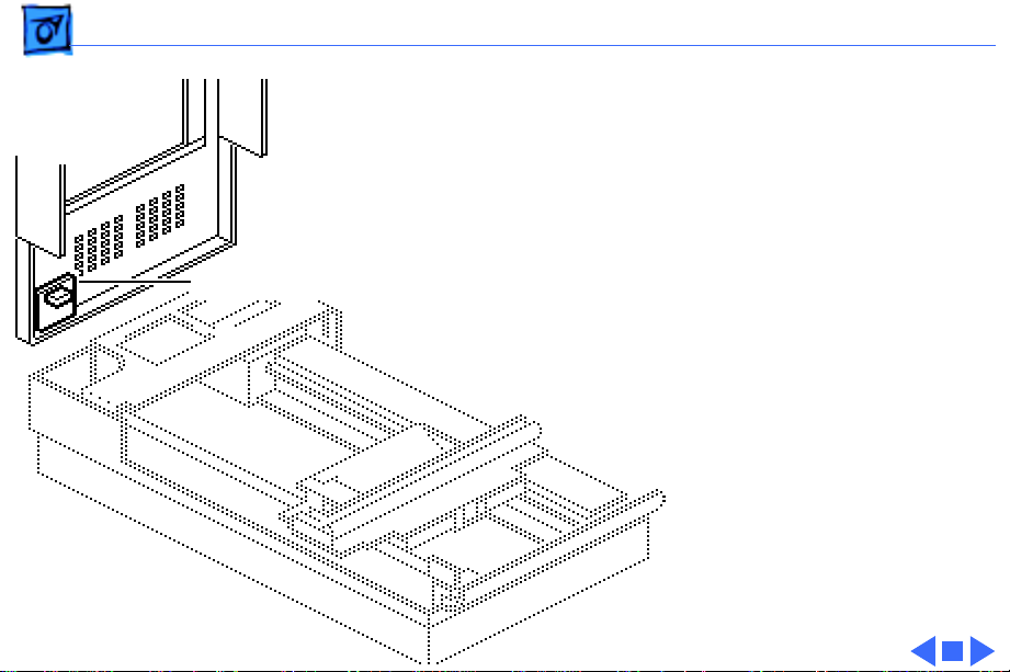
Selecting Voltage
Screw
Switch Cover
No preliminary steps are
required before you begin
this procedure.
1 Remove the screw and
the switch cover.
Page 59

Additional Procedures Selecting Voltage - 2
2 Using a coin or a flat-
blade screwdriver,
rotate the voltage
selector to match the
Voltage Selector
incoming voltage.
Page 60

Additional Procedures Logic Board Fuse - 3
Logic Board Fuse
Before you begin, remove
the logic board.
Logic Board Fuse
(1A)
Caution:
precautions in Bulletins/
Safety.
Note:
procedure on the 4-bit
scanner only. Return the 8bit logic board (in its
shielded case) to Apple for
repairs.
Review the ESD
Perform this
Page 61

Additional Procedures Logic Board Fuse - 4
Pry up one end of the fuse at
a time and remove the fuse.
Replacement Caution:
Use a replacement fuse
with the correct rating.
Logic Board Fuse
(1A)
Page 62

Additional Procedures Power Supply Fuses - 5
Power Supply Fuses
No preliminary steps are
required before you begin
this procedure.
Caution
precautions in Bulletins/
Safety.
: Review the ESD
Page 63

Additional Procedures Power Supply Fuses - 6
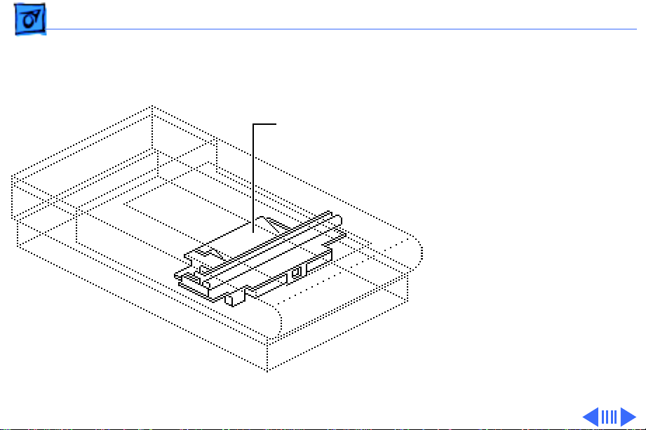
1 Lift the center of the left
guide rail housing and
remove it from the left
guide rail.
Left Guide Rail Housing
AC Switch Cover
Page 64

Additional Procedures Power Supply Fuses - 7
2 Remove fuses 1A and 3A.
3 Push in the tabs and
remove the AC switch
cover.
4 Remove fuse 2A.
(3A)
(1A)
AC Switch
Cover
(2A)
Replacement Caution:
Use a replacement fuse
with the correct rating.
Page 65

Additional Procedures Lamp Replacement - 8
Lamp Replacement
No preliminary steps are
required before you begin
this procedure.
1 Lift the cover to the
vertical position.
Note:
To move the optical
assembly to the home
position, switch the
scanner on and then off.
2 Using a coin or flat-
blade screwdriver,
unscrew the lamp lock
Lamp Lock Button
button.
Page 66

Additional Procedures Lamp Replacement - 9
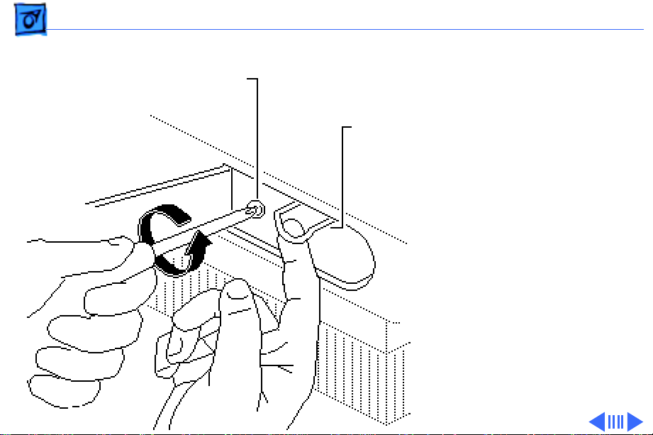
3 To remove the lamp
Retaining Screw
assembly, pull on the
wire handle and
Wire Handle
unscrew the retaining
screw.
Page 67

Additional Procedures Lamp Replacement - 10
Metal End
of Lamp
Warning:
Do not pry the
glass area of the lamp.
The lamp could shatter.
4 Carefully pry one metal
end of the lamp to
disengage the lamp from
the socket.
5 Pull the lamp from the
other socket.
Page 68

Additional Procedures Lamp Replacement - 11
Replacement Note:
When replacing the lamp
and lamp assembly,
make sure that
• The lamp is free of
Lamp
fingerprints. Wipe it
with a soft cloth prior
to inserting it into the
lamp assembly.
Lamp Assembly
• The printing on the
lamp faces the lamp
assembly.
• The lamp assembly
seats securely in the
left retaining flanges.
Page 69

Additional Procedures Lamp Replacement - 12
• The wire handle is in
the down position
before you close the
lamp cover.
• The lamp lock button
Lamp
is tight. The button
activates interlock
switches.
Lamp Assembly
Page 70

Additional Procedures Voltage Conversion - 13
Voltage
Transformer
Conversion
Before you begin, remove
the transformer.
Note:
Do not remove the
transformer bracket from
the transformer.
Page 71

Additional Procedures Voltage Conversion - 14
To convert a 110 V
scanner (without the
Transformer
universal voltage
selector) to a universal
model, remove the
transformer and
bracket plate assembly
and install the universal
model transformer and
bracket plate assembly.
Replacement Note:
Before switching on
scanner power, refer to
“Selecting Voltage.”
Page 72

Additional Procedures Logic Board Modification - 15
Logic Board Modification
Before you begin, remove
the logic board.
4-Bit Logic Board
Caution
precautions in Bulletins/
Safety.
Note:
procedure on the 4-bit
scanner only. Return the 8bit logic board (in its metal
shield) to Apple for
modifications.
: Review the ESD
Perform this
Page 73

Additional Procedures Logic Board Modification - 16
CA4
CA5
CA6
Caution:
Do not touch
other components on the
logic board.
Using diagonal cutters, cut
each lead of capacitors CA4,
CA5, and CA6 just above the
board surface and remove
the capacitors.
Page 74

K
Service Source
Exploded V ie w
Apple Scanners
Page 75

Exploded View 1
Logic Board
Carrier
Motor
Transformer
Top Cover
Power Supply Board
Glass Cover
Assembly
On/Off
Switch
Assembly
Optical
Assembly
Inverter
Assembly
 Loading...