


KH 26 XE, KH 28 Super XE
Original instructions Originalbetriebsanleitung Notice originale Istruzioni originali Manual original
Manual original
Oorspronkelijke gebruiksaanwijzing
Original brugsanvisning Original bruksanvisning Bruksanvisning i original Alkuperäiset ohjeet Πρωτότυπο οδηγιών χρήσης Orijinal işletme talimatı Původním návodem k používání Pôvodný návod na použitie
Instrukcją oryginalną Eredeti használati utasítás Izvirna navodila Originalne pogonske upute Instrukcijām oriģinālvalodā Originali instrukcija Algupärane kasutusjuhend
Оригинальное руководство по эксплуатации
Оригинално ръководство за експлоатация
Instrucţiuni de folosire originale
Оригинален прирачник за работа Оригінал інструкції з експлуатації
ﺔﯾﻠﺻﻷا تﺎﻣﯾﻠﻌﺗﻟا

ENGLISH |
1 |
2 |
3 |
Picture section |
|
|
|
with operating description and functional description |
|
DEUTSCH |
1 |
2 |
3 |
Bildteil |
|
|
|
mit Anwendungsund Funktionsbeschreibungen |
|
FRANÇAIS |
1 |
2 |
3 |
Partie imagée |
|
|
|
avec description des applications et des fonctions |
|
ITALIANO |
1 |
2 |
3 |
Sezione illustrata |
|
|
|
con descrizione dell'applicazione e delle funzioni |
|
ESPAÑOL |
1 |
2 |
3 |
Sección de ilustraciones |
|
|
|
con descripción de aplicación y descripción funcional |
|
PORTUGUES |
1 |
2 |
3 |
Parte com imagens |
|
|
|
explicativas contendo descrição operacional e funcional |
|
NEDERLANDS |
1 |
2 |
3 |
Beeldgedeelte |
|
|
|
met toepassingsen functiebeschrijvingen |
|
DANSK |
1 |
2 |
3 |
Billeddel |
|
|
|
med anvendelsesog funktionsbeskrivelser |
|
NORSK |
1 |
2 |
3 |
Bildedel |
|
|
|
med bruksog funksjonsbeskrivelse |
|
SVENSKA |
1 |
2 |
3 |
Bilddel |
|
|
|
med användningsoch funktionsbeskrivning |
|
SUOMI |
1 |
2 |
3 |
Kuvasivut |
|
|
|
käyttöja toimintakuvaukset |
|
ΕΛΛΗΝΙΚΑ |
1 |
2 |
3 |
Τμήμα εικόνων |
|
|
|
με περιγραφές χρήσης και λειτουργίας |
|
TÜRKÇE |
1 |
2 |
3 |
Resim bölümü |
|
|
|
Uygulama ve fonksiyon açıklamaları ile birlikte |
|
ČESKY |
1 |
2 |
3 |
Obrazová část |
|
|
|
s popisem aplikací a funkcí |
|
SLOVENSKY |
1 |
2 |
3 |
Obrazová časťs popisom aplikácií a funkcií |
|
|
|
|
|
POLSKI |
1 |
2 |
3 |
Część rysunkowa z opisami zastosowania i działania |
|
|
|
|
|
MAGYAR |
1 |
2 |
3 |
Képes részalkalmazásiés működési leírásokkal |
|
|
|
|
|
SLOVENSKO |
1 |
2 |
3 |
Del slikez opisom uporabe in funkcij |
|
|
|
|
|
HRVATSKI |
1 |
2 |
3 |
Dio sa slikamasa opisima primjene i funkcija |
|
|
|
|
|
LATVISKI |
1 |
2 |
3 |
Attēla daļa ar lietošanas un funkciju aprakstiem |
|
|
|
|
|
LIETUVIŠKAI |
1 |
2 |
3 |
Paveikslėlio dalissu vartojimo instrukcija ir funkcijų aprašymais |
|
|
|
|
|
EESTI |
1 |
2 |
3 |
Pildiosa kasutusjuhendi ja funktsioonide kirjeldusega |
|
|
|
|
|
РУССКИЙ |
1 |
2 |
3 |
Раздел иллюстрацийс описанием эксплуатации и функций |
|
|
|
|
|
БЪЛГАРСКИ |
1 |
2 |
3 |
Част със снимки с описания за приложение и функции |
|
|
|
|
|
ROMÂNIA |
1 |
2 |
3 |
Secvenţa de imagine cu descrierea utilizării şi a funcţionării |
|
|
|
|
|
МАКЕДОНСКИ |
1 |
2 |
3 |
Дел со сликисо описи за употреба и функционирање |
|
|
|
|
|
УКРАЇНСЬКА |
1 |
2 |
3 |
Частина з зображеннями з описом робіт та функцій |
|
|
|
|
|
ﻲﺑرﻋ |
1 |
2 |
3 |
ﻲﻔﯾظوﻟاو ﻲﻠﯾﻐﺷﺗﻟا فﺻوﻟا ﮫﺑ دﺟوﯾ روﺻﻟا مﺳﻗ |
|
|
|
|
4
4
4
4
4
4
4
4
4
4
4
4
4
4
4
4
4
4
4
4
4
4
4
4
4
4
4
4
Text section with Technical Data, important Safety and Working Hints |
18 |
and description of Symbols |
|
Textteil mit Technischen Daten, wichtigen Sicherheitsund Arbeitshinweisen |
20 |
und Erklärung der Symbole. |
|
Partie textuelle avec les données techniques, les consignes importantes de sécurité et de travail ainsi que |
22 |
l’explication des pictogrammes. |
|
Sezione testo con dati tecnici, importanti informazioni sulla sicurezza e sull‘utilizzo, |
24 |
spiegazione dei simboli. |
|
Sección de texto con datos técnicos, indicaciones importantes de seguridad y trabajo y explicación de los símbolos. |
26 |
Parte com texto explicativo contendo Especifi cações técnicas, Avisos de segurança e de operação e a Descrição |
28 |
dos símbolos. |
|
Tekstgedeelte met technische gegevens, belangrijke veiligheidsen arbeidsinstructies en verklaring van de |
30 |
symbolen. |
|
Tekstdel med tekniske data, vigtige sikkerhedsog arbejdsanvisninger |
32 |
og symbolforklaring. |
|
Tekstdel med tekniske data, viktige sikkerhetsog arbeidsinstruksjoner |
34 |
og forklaring av symbolene. |
|
Textdel med tekniska informationer, viktiga säkerhetsoch användningsinstruktioner |
36 |
samt symbolförklaringar. |
|
Tekstisivut: tekniset tiedot, tärkeät turvallisuusja työskentelyohjeet |
38 |
sekä merkkien selitykset. |
|
Τμήμα κειμένου με τεχνικά χαρακτηριστικά, σημαντικές υποδείξεις ασφαλείας |
40 |
και εργασίας και εξήγηση των συμβόλων. |
|
Teknik bilgileri, önemli güvenlik ve çalışma açıklamalarını ve de sembollerin açıklamalarını |
42 |
içeren metin bölümü. |
|
Textová část s technickými daty, důležitými bezpečnostními a pracovními pokyny |
44 |
a s vysvětlivkami symbolů |
|
Textová časť s technickými dátami, dôležitými bezpečnostnými a pracovnými pokynmi |
46 |
a s vysvetlivkami symbolov |
|
Część opisowa z danymi technicznymi, ważnymi wskazówkami dotyczącymi bezpieczeństwa i pracy oraz |
48 |
objaśnieniami symboli. |
|
Szöveges rész műszaki adatokkal, fontos biztonságiés munkavégzési útmutatásokkal, valamint a szimbólumok |
50 |
magyarázata. |
|
|
52 |
Del besedila s tehničnimi podatki, pomembnimi varnostnimi opozorili in delovnimi navodili |
|
in pojasnili simbolov. |
|
Dio štiva sa tehničkim podacima, važnim sigurnosnim i radnim uputama |
54 |
i objašnjenjem simbola. |
|
Teksta daļa ar tehniskajiem parametriem, svarīgiem drošības un darbības norādījumiem, |
56 |
simbolu atšifrējumiem. |
|
Teksto dalis su techniniais duomenimis, svarbiomis saugumo ir darbo instrukcijomis |
58 |
bei simbolių paaiškinimais. |
|
Tekstiosa tehniliste näitajate, oluliste ohutusja tööjuhenditega |
60 |
ning sümbolite kirjeldustega. |
|
Текстовый раздел, включающий технические данные, важные рекомендации по безопасности и |
62 |
эксплуатации, а также описание используемых символов. |
|
Част с текст с технически данни, важни указания за безопасност и работа |
64 |
и разяснение на символите. |
|
Porţiune de text cu date tehnice, indicaţii importante privind siguranţa şi modul de lucru |
66 |
şi descrierea simbolurilor. |
|
Текстуален дел со Технички карактеристики, важни безбедносни и работни упатства |
68 |
и објаснување на симболите. |
|
Текстова частина з технічними даними, важливими вказівками з техніки безпеки та експлуатації |
70 |
і поясненням символів. |
|
زوﻣرﻟا فﺻوو لﻣﻌﻟاو ﺔﻣﻼﺳﻠﻟ ﺔﻣﺎﮭﻟا ﺢﺋﺎﺻﻧﻟاو ﺔﯾﻧﻔﻟا تﺎﻧﺎﯾﺑﻟﺎﺑ دوزﻣﻟا ﻲﺻﻧﻟا مﺳﻘﻟا |
75 |
2 
 3
3
|
|
|
|
|
6 |
12 |
|||
|
|
|
|
|
|
|
|
|
|
14
7
 15 10
15 10
KH 28 Super XE
8 |
9 |
11 |
|
|
|
|
|
16
STOP START
4 |
|
|
|
5 |
|
|

 1
1
1 |
2 |
3
2
4
3
TEST
click
click
6 
 7
7
 1
1
 1
1
2 |
2 |
3
8 
 9
9
START
1
STOP
2
1
START/LOCK
2
1 2
STOP
1
2
10 |
|
|
|
11 |
|
|

 1
1
1 2
1 2
2
KH 28 Super XE
1 |
2 |
|
KH 28 Super XE |
1 2
KH 28 Super XE
12 
 13
13

KH 28 Super XE
14 
 15
15

16 
 17
17
TECHNICAL DATA |
ROTARY HAMMER |
KH 26 XE |
|
KH 28 SUPER XE |
Production code....................................................................... |
..................... |
4289 11 04... |
.............4281 91 04... |
|
Rated input |
|
...000001-999999 |
...000001-999999 |
|
......................... |
800W......................... |
|
1010W |
|
Output...................................................................................... |
......................... |
400W........................... |
|
505W |
No-load speed......................................................................... |
.................... |
0-1500min-1.................. |
|
0-1500min-1 |
Speed under load max. ........................................................... |
....................... |
1300min-1..................... |
|
1500min-1 |
Rate of percussion under load max......................................... |
....................... |
4500min-1..................... |
|
5000min-1 |
Impact energy per stroke according to EPTA-Procedure 05/2009............................... |
2,5J.............................. |
|
2,8J |
|
Impact energy per stroke (pre 2009)....................................... |
.......................... |
2,9J.............................. |
|
3,1J |
Drilling capacity in concrete..................................................... |
........................... |
26mm .......................... |
|
28mm |
Drilling capacity in steel........................................................... |
........................... |
13mm .......................... |
|
13mm |
Drilling capacity in wood.......................................................... |
........................... |
30mm .......................... |
|
30mm |
Light core cutter in bricks and limestone................................. |
........................... |
50mm .......................... |
|
50mm |
Chuck neck diameter............................................................... |
........................... |
43mm .......................... |
|
43mm |
Weight according EPTA-Procedure 01/2003..................................................... |
2,8kg............................ |
|
2,8kg |
|
Noise Information |
|
|
|
|
Measured values determined according to EN 60745. |
|
|
|
|
Typically, the A-weighted noise levels of the tool are: |
89dB (A) |
|
92dB (A) |
|
Sound pressure level (K=3dB(A)) ....................................... |
........................... |
|
||
Sound power level (K=3dB(A))............................................ |
......................... |
100dB (A).................... |
|
103dB (A) |
Wear ear protectors! |
|
|
|
|
Vibration Information |
|
|
|
|
Total vibration values (vector sum in the three axes) |
|
|
|
|
determined according to EN 60745. |
|
|
|
|
Vibration emission value ah: |
|
13,3m/s2 |
|
15,4m/s2 |
Hammer-drilling in concrete: vibration emission value ah ............................... |
|
|||
Uncertainty K = ....................................................................... |
.......................... |
1,5m/s2......................... |
|
1,5m/s2 |
Chiselling: vibration emission value ah .................................... |
........................ |
11,6m/s2....................... |
|
13,5m/s2 |
Uncertainty K = ....................................................................... |
.......................... |
1,5m/s2......................... |
|
1,5m/s2 |
WARNING
The vibration emission level given in this information sheet has been measured in accordance with a standardised test given in EN 60745 and may be used to compare one tool with another. It may be used for a preliminary assessment of exposure.
The declared vibration emission level represents the main applications of the tool. However if the tool is used for di erent applications, with di erent accessories or poorly maintained, the vibration emission may di er. This may signifi cantly increase the exposure level over the total working period.
An estimation of the level of exposure to vibration should also take into account the times when the tool is switched o or when it is running but not actually doing the job. This may signifi cantly reduce the exposure level over the total working period.
Identify additional safety measures to protect the operator from the e ects of vibration such as: maintain the tool and the accessories, keep the hands warm, organisation of work patterns.
 WARNING! Read all safety warnings and all instructions. Failure to follow the warnings and instructions may result in electric shock, fi re and/or serious injury.
Save all warnings and instructions for future reference. 
 ROTARY HAMMER SAFETY WARNINGS
Wear ear protectors when impact drilling. Exposure to noise can cause hearing loss.
Use auxiliary handle(s), if supplied with the tool. Loss of control can cause personal injury.
Hold the power tool by insulated gripping surfaces only, when performing an operation where the cutting accessory may contact hidden wiring or its own cord.
Cutting accessory contacting a "live" wire may make exposed metal parts of the power tool "live" and could give the operator an electric shock.
ADDITIONAL SAFETY AND WORKING INSTRUCTIONS
Use protective equipment. Always wear safety glasses when working with the machine. The use of protective clothing is recommended, such as dust mask, protective gloves, sturdy non-slip footwear, helmet and ear defenders.
The dust produced when using this tool may be harmful to health. Do not inhale the dust. Wear a suitable dust protection mask.
Do not machine any materials that present a danger to health (e.g. asbestos).
Switch the device o immediately if the insertion tool stalls! Do not switch the device on again while the insertion tool is stalled, as doing so could trigger a sudden recoil with a high reactive force. Determine why the insertion tool stalled and rectify this, paying heed to the safety instructions.
The possible causes may be:
•it is tilted in the workpiece to be machined
•it has pierced through the material to be machined
•the power tool is overloaded
Do not reach into the machine while it is running.
The insertion tool may become hot during use. WARNING! Danger of burns
•when changing tools
•when setting the device down
Chips and splinters must not be removed while the machine is running.
Keep mains lead clear from working range of the machine. Always lead the cable away behind you.
When working in walls ceiling, or fl oor, take care to avoid electric cables and gas or waterpipes.
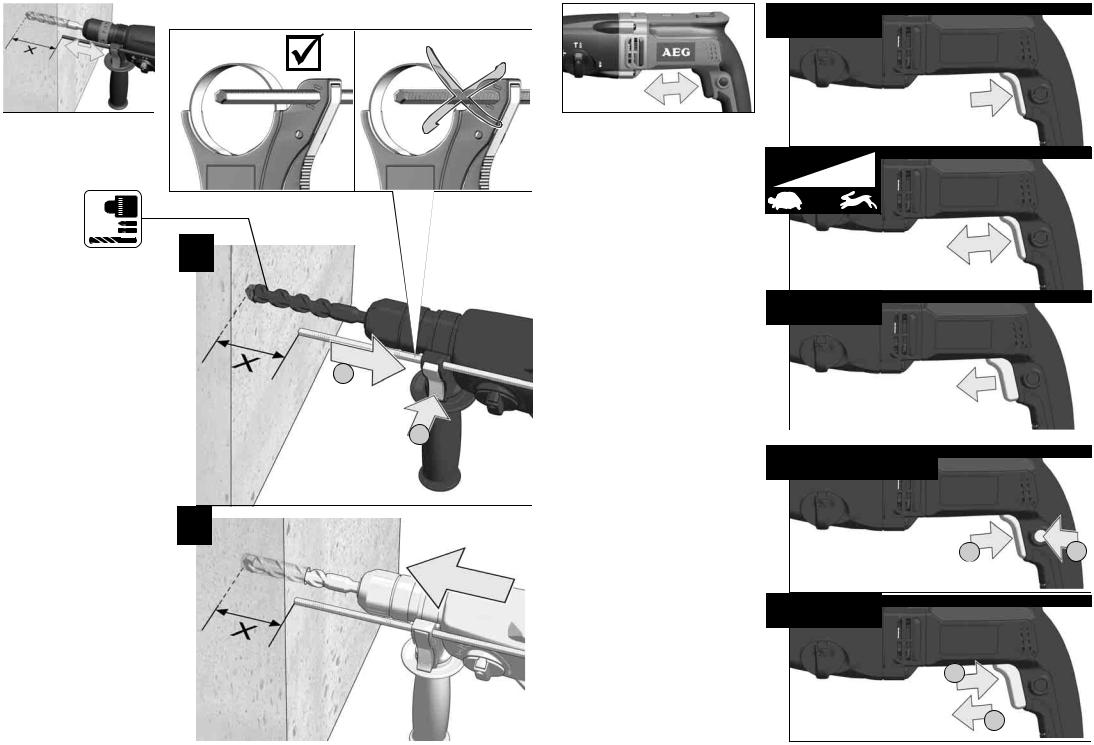
Clamp your workpiece with a clamping device. Unclamped workpieces can cause severe injury and damage.
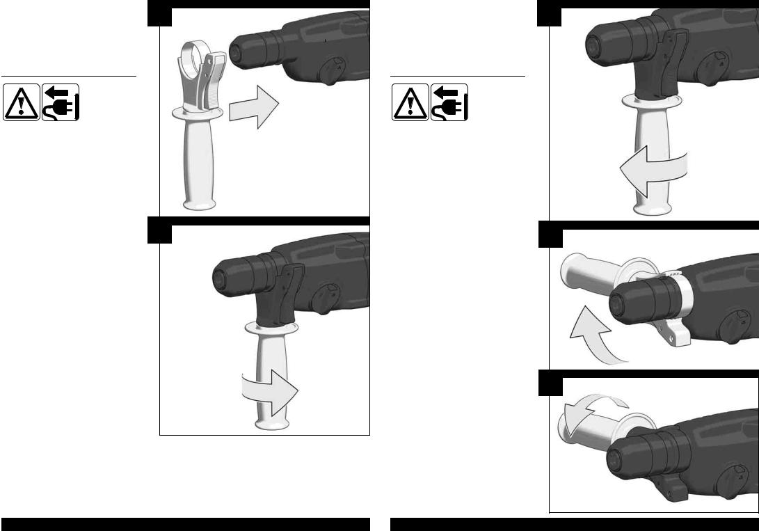
Always disconnect the plug from the socket before carrying out any work on the machine.
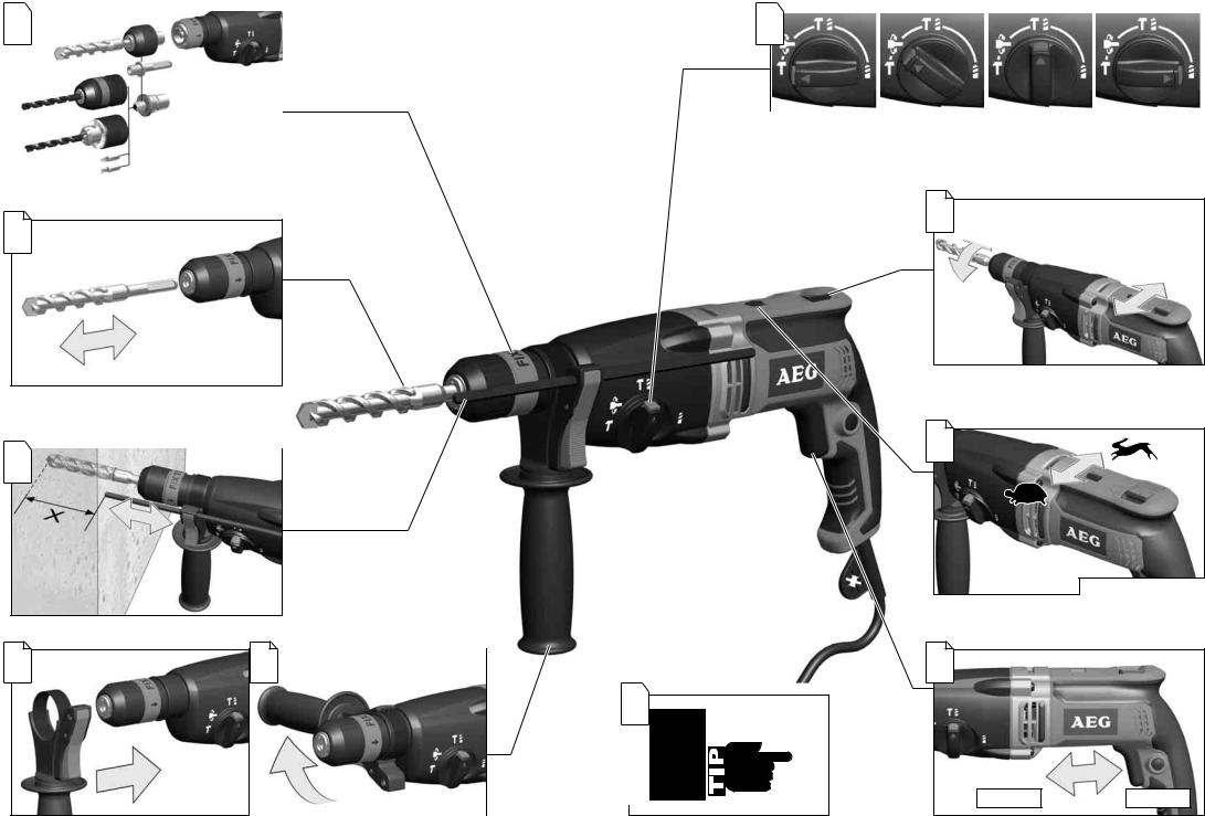
When working with large drill diameters, the auxiliary handle must be fastened in a right angle with the main handle (see illustrations, section "Twisting the handle").
SPECIFIED CONDITIONS OF USE
The rotary pneumatic hammer can be used for hammer drilling, chiselling in stone and concrete and drilling in wood, metal as well as plastic.
Do not use this product in any other way as stated for normal use.
EC-DECLARATION OF CONFORMITY
We declare under our sole responsibility that the product described under “Technical Data” fulfi lls all the relevant provisions of the directives 2011/65/EU (RoHs), 2014/30/ EU, 2006/42/EC and the following harmonized standards have been used:
EN 60745-1:2009 + A11:2010 EN 60745-2-6:2010
EN 55014-1:2006+A1:2009+A2:2011 EN 55014-2:2015
EN 61000-3-2:2014
EN 61000-3-3:2013
EN 50581:2012
Winnenden, 2017-08-10
Alexander Krug
Managing Director
Authorized to compile the technical fi le
Techtronic Industries GmbH Max-Eyth-Straße 10 71364 Winnenden Germany
MAINS CONNECTION
Appliances used at many di erent locations including wet room and open air must be connected via a residual current device (FI, RCD, PRCD) of 30mA or less.
Connect only to single-phase AC current and only to the system voltage indicated on the rating plate. It is also possible to connect to sockets without an earthing contact as the design conforms to safety class II.
Make sure the machine is switched o before plugging in.
This is a device for professional use which may slightly exceed the guide values for current harmonics when it is connected to the public low voltage mains supply. You should therefore contact your energy supply company before you connect the device to the public low voltage mains supply.
MAINTENANCE
The ventilation slots of the machine must be kept clear at all times.
Important note! If the carbon brushes are worn, in addition to exchanging the brushes the tool should be sent to after-sales service. This will ensure long service life and top performance.
If the supply cord of this appliance is damaged, it must only be replaced by a repair shop appointed by the manufacturer, to avoid hazardous situations.
Use only AEG accessories and spare parts. Should components need to be replaced which have not been described, please contact one of our AEG service agents (see our list of guarantee/service addresses).
If needed, an exploded view of the tool can be ordered. Please state the Article No. as well as the machine type printed on the label and order the drawing at your local
service agents or directly at: Techtronic Industries GmbH, Max-Eyth-Straße 10, 71364 Winnenden, Germany.
SYMBOLS
CAUTION! WARNING! DANGER!
Always disconnect the plug from the socket before carrying out any work on the machine.
Please read the instructions carefully before starting the machine.
Accessory - Not included in standard equipment, available as an accessory.
Do not dispose of electric tools together with household waste material.
Electric tools and electronic equipment that have reached the end of their life must be collected separately and returned to an environmentally compatible recycling facility. Check with your local authority or retailer for recycling advice and collection point.
Class II tool, tool in which protection against electric shock does not rely on basic insulation only, but in which additional safety precautions, such as double insulation or reinforced insulation, are provided.
There being no provision for protective earthing or reliance upon installation conditions.
European Conformity Mark
National mark of conformity Ukraine
EurAsian Conformity Mark.
18 |
ENGLISH |
|
ENGLISH |
19 |
TECHNISCHE DATEN |
BOHRHAMMER |
KH 26 XE |
|
KH 28 SUPER XE |
Produktionsnummer ................................................................ |
..................... |
4289 11 04... |
.............4281 91 04... |
|
Nennaufnahmeleistung |
|
...000001-999999 |
...000001-999999 |
|
......................... |
800W......................... |
|
1010W |
|
Abgabeleistung........................................................................ |
......................... |
400W........................... |
|
505W |
Leerlaufdrehzahl...................................................................... |
.................... |
0-1500min-1.................. |
|
0-1500min-1 |
Lastdrehzahl max.................................................................... |
....................... |
1300min-1..................... |
|
1500min-1 |
Lastschlagzahl max................................................................. |
....................... |
4500min-1..................... |
|
5000min-1 |
Einzelschlagstärke entsprechend EPTA-Procedure 05/2009....................................... |
2,5J.............................. |
|
2,8J |
|
Einzelschlagstärke (pre 2009)................................................. |
.......................... |
2,9J.............................. |
|
3,1J |
Bohr-ø in Beton ....................................................................... |
........................... |
26mm .......................... |
|
28mm |
Bohr-ø in Stahl......................................................................... |
........................... |
13mm .......................... |
|
13mm |
Bohr-ø in Holz.......................................................................... |
........................... |
30mm .......................... |
|
30mm |
Leichtbohrkrone in Ziegel und Kalksandstein..................................................... |
50mm .......................... |
|
50mm |
|
Spannhals-ø............................................................................ |
........................... |
43mm .......................... |
|
43mm |
Gewicht nach EPTA-Prozedur 01/2003................................... |
.......................... |
2,8kg............................ |
|
2,8kg |
Geräuschinformationen |
|
|
|
|
Messwerte ermittelt entsprechend EN 60745. |
|
|
|
|
Der A-bewertete Geräuschpegel des Gerätes beträgt |
|
|
|
|
typischerweise: |
|
89dB (A) |
|
92dB (A) |
Schalldruckpegel (K=3dB(A)).............................................. |
........................... |
|
||
Schalleistungspegel (K=3dB(A))......................................... |
......................... |
100dB (A).................... |
|
103dB (A) |
Gehörschutz tragen! |
|
|
|
|
Vibrationsinformationen |
|
|
|
|
Schwingungsgesamtwerte (Vektorsumme dreier Richtungen) |
|
|
|
|
ermittelt entsprechend EN 60745: |
|
|
|
|
Schwingungsemissionswert ah: |
|
13,3m/s2 |
|
15,4m/s2 |
Hammerbohren in Beton:Schwingungsemissionswert ah ............................. |
|
|||
Unsicherheit K = .................................................................. |
.......................... |
1,5m/s2......................... |
|
1,5m/s2 |
Meißeln: Schwingungsemissionswert ah: ............................. |
........................ |
11,6m/s2....................... |
|
13,5m/s2 |
Unsicherheit K = .................................................................. |
.......................... |
1,5m/s2......................... |
|
1,5m/s2 |
WARNUNG
Der in diesen Anweisungen angegebene Schwingungspegel ist entsprechend einem in EN 60745 genormten Messverfahren gemessen worden und kann für den Vergleich von Elektrowerkzeugen miteinander verwendet werden. Er eignet sich auch für eine vorläufi ge Einschätzung der Schwingungsbelastung.
Der angegebene Schwingungspegel repräsentiert die hauptsächlichen Anwendungen des Elektrowerkzeugs. Wenn allerdings das Elektrowerkzeug für andere Anwendungen, mit abweichenden Einsatzwerkzeugen oder ungenügender Wartung eingesetzt wird, kann der Schwingungspegel abweichen. Dies kann die Schwingungsbelastung über den gesamten Arbeitszeitraum deutlich erhöhen.
Für eine genaue Abschätzung der Schwingungsbelastung sollten auch die Zeiten berücksichtigt werden, in denen das Gerät abgeschaltet ist oder zwar läuft, aber nicht tatsächlich im Einsatz ist. Dies kann die Schwingungsbelastung über den gesamten Arbeitszeitraum deutlich reduzieren.
Legen Sie zusätzliche Sicherheitsmaßnahmen zum Schutz des Bedieners vor der Wirkung von Schwingungen fest wie zum Beispiel: Wartung von Elektrowerkzeug und Einsatzwerkzeugen, Warmhalten der Hände, Organisation der Arbeitsabläufe.
 WARNUNG! Lesen Sie alle Sicherheitshinweise und Anweisungen. Versäumnisse bei der Einhaltung der Sicherheitshinweise und Anweisungen können elektrischen Schlag, Brand und/oder schwere Verletzungen verursachen.
Bewahren Sie alle Sicherheitshinweise und Anweisungen für die Zukunft auf.

 SICHERHEITSHINWEISE FÜR BOHRHAMMER
Tragen Sie Gehörschutz beim Schlagbohren. Die Einwirkung von Lärm kann Gehörverlust bewirken.
Benutzen Sie die mit dem Gerät gelieferten Zusatzhandgrie, wenn diese mitgeliefert werden. Der Verlust der Kontrolle kann zu Verletzungen führen.
Halten Sie das Elektrowerkzeug nur an den isolierten Griflächen, wenn Sie Arbeiten ausführen, bei denen das Einsatzwerkzeug verborgene Stromleitungen oder das eigene Netzkabel treen kann. Der Kontakt mit einer spannungsführenden Leitung kann auch metallene Geräteteile unter Spannung setzen und zu einem elektrischen Schlag führen.
WEITERE SICHERHEITSUND ARBEITSHINWEISE
Schutzausrüstung verwenden. Beim Arbeiten mit der Maschine stets Schutzbrille tragen. Schutzkleidung wie Staubschutzmaske, Schutzhandschuhe, festes und
rutschsicheres Schuhwerk, Helm und Gehörschutz werden empfohlen.
Beim Arbeiten entstehender Staub ist oft gesundheitsschädlich und sollte nicht in den Körper gelangen. Geeignete Staubschutzmaske tragen.
Es dürfen keine Materialien bearbeitet werden, von denen eine Gesundheitsgefährdung ausgeht (z.B. Asbest).
Beim Blockieren des Einsatzwerkzeuges bitte das Gerät sofort ausschalten! Schalten Sie das Gerät nicht wieder ein, solange das Einsatzwerkzeug blockiert ist; hierbei könnte ein Rückschlag mit hohem Reaktionsmoment entstehen. Ermitteln und beheben Sie die Ursache für die Blockierung des Einsatzwerkzeuges unter Berücksichtigung der Sicherheitshinweise.
Mögliche Ursachen dafür können sein:
•Verkanten im zu bearbeitenden Werkstück
•Durchbrechen des zu bearbeitenden Materials
•Überlasten das Elektrowerkzeuges
Greifen Sie nicht in die laufende Maschine.
Das Einsatzwerkzeug kann während der Anwendung heiß werden.
WARNUNG! Verbrennungsgefahr
•bei Werkzeugwechsel
•bei Ablegen des Gerätes
Späne oder Splitter dürfen bei laufender Maschine nicht entfernt werden.
Anschlusskabel stets vom Wirkungsbereich der Maschine fernhalten. Kabel immer nach hinten von der Maschine wegführen.
Beim Arbeiten in Wand, Decke oder Fußboden auf elektrische Kabel, Gasund Wasserleitungen achten.
Sichern Sie Ihr Werkstück mit einer Spannvorrichtung. Nicht gesicherte Werkstücke können schwere Verletzungen und Beschädigungen verursachen.
Vor allen Arbeiten an der Maschine Stecker aus der Steckdose ziehen.
Bei großen Bohrdurchmessern muss der Zusatzhandgri rechtwinklig zum Haupthandgri befestigt werden (siehe auch im Bildteil, Abschnitt "Handgri verdrehen").
BESTIMMUNGSGEMÄSSE VERWENDUNG
Der Bohrhammer ist universell einsetzbar zum Hammerbohren und Meißeln in Gestein und Beton und zum Bohren in Holz, Metall und Kunststo .
Dieses Gerät darf nur wie angegeben bestimmungsgemäß verwendet werden.
CE-KONFORMITÄTSERKLÄRUNG
Wir erklären in alleiniger Verantwortung, dass das unter „Technische Daten“ beschriebene Produkt mit alle relevanten Vorschriften der Richtline 2011/65/EU (RoHs), 2014/30/EU, 2006/42/EG und den folgenden harmonisierten normativen Dokumenten übereinstimmt:
EN 60745-1:2009 + A11:2010 EN 60745-2-6:2010
EN 55014-1:2006+A1:2009+A2:2011 EN 55014-2:2015
EN 61000-3-2:2014
EN 61000-3-3:2013
EN 50581:2012
Winnenden, 2017-08-10
Alexander Krug
Managing Director
Bevollmächtigt die technischen Unterlagen zusammenzustellen.
Techtronic Industries GmbH Max-Eyth-Straße 10 71364 Winnenden Germany
NETZANSCHLUSS
Steckdosen in Feuchträumen und Außenbereichen müssen mit Fehlerstrom-Schutzschaltern (FI, RCD, PRCD) ausgerüstet sein. Das verlangt die Installationsvorschrift für Ihre Elektroanlage. Bitte beachten Sie das bei der Verwendung unseres Gerätes.
Nur an Einphasen-Wechselstrom und nur an die auf dem Leistungsschild angegebene Netzspannung anschließen. Anschluss ist auch an Steckdosen ohne Schutzkontakt möglich, da ein Aufbau der Schutzklasse II vorliegt.
Gerät nur ausgeschaltet an die Steckdose anschließen.
Dies ist ein Gerät zur professionellen Nutzung, das die Richtwerte für Stromoberwellen beim Anschluss an das ö entliche Niederspannungsnetz geringfügig überschreiten kann. Kontaktieren Sie daher vor dem Anschluss des Gerätes an das ö entliche Niederspannungsnetz gegebenenfalls Ihr zuständiges Energieversorgungsunternehmen.
WARTUNG
Stets die Lüftungsschlitze der Maschine sauber halten.
Bei abgenutzten Kohlebürsten sollte zusätzlich zum Kohlebürstenwechsel ein Kundendienst in einer Servicewerkstatt durchgeführt werden. Dies erhöht die Lebensdauer der Maschine und garantiert eine ständige Betriebsbereitschaft.
Wenn die Netzanschlussleitung beschädigt ist, muss diese durch eine Kundendienststelle ausgewechselt werden, um Gefährdungen zu vermeiden.
Nur AEG Zubehör und Ersatzteile verwenden. Bauteile, deren Austausch nicht beschrieben wurde, bei einer AEG Kundendienststelle auswechseln lassen (Broschüre Garantie/Kundendienstadressen beachten).
Bei Bedarf kann eine Explosionszeichnung des Gerätes unter Angabe der Maschinen Type und der sechsstelligen Nummer auf dem Leistungsschild bei Ihrer Kundendienststelle oder direkt bei Techtronic Industries GmbH, Max-Eyth-Straße 10, 71364 Winnenden, Germany angefordert werden.
SYMBOLE
ACHTUNG! WARNUNG! GEFAHR!
Vor allen Arbeiten an der Maschine Stecker aus der Steckdose ziehen.
Bitte lesen Sie die Gebrauchsanweisung vor Inbetriebnahme sorgfältig durch.
Zubehör - Im Lieferumfang nicht enthalten, empfohlene Ergänzung aus dem Zubehörprogramm.
Elektrogeräte dürfen nicht zusammen mit dem Hausmüll entsorgt werden. Elektrische und elektronische Geräte sind getrennt zu sammeln und zur umweltgerechten Entsorgung bei einem Verwertungsbetrieb abzugeben. Erkundigen Sie sich bei den örtlichen Behörden oder bei Ihrem Fachhändler nach Recyclinghöfen und Sammelstellen.
Elektrowerkzeug der Schutzklasse II. Elektrowerkzeug, bei dem der Schutz vor einem elektrischen Schlag nicht nur von der Basisisolierung abhängt, sondern auch davon, dass zusätzliche Schutzmaßnahmen, wie doppelte Isolierung oder verstärkte Isolierung, angewendet werden.
Es gibt keine Vorrichtung zum Anschluss eines Schutzleiters.
CE-Zeichen
Nationales Konformitätszeichen Ukraine
EurAsian Konformitätszeichen.
20 |
DEUTSCH |
|
DEUTSCH |
21 |
CARACTÉRISTIQUES TECHNIQUES MARTEAU PERFORATEUR |
KH 26 XE |
|
KH 28 SUPER XE |
Numéro de série........................................................................................... |
4289 11 04... |
.............4281 91 04... |
|
Puissance nominale de réception |
...000001-999999 |
...000001-999999 |
|
800W......................... |
|
1010W |
|
Puissance utile ................................................................................................. |
400W........................... |
|
505W |
Vitesse de rotation à vide............................................................................ |
0-1500min-1.................. |
|
0-1500min-1 |
Vitesse de rotation en charge......................................................................... |
1300min-1..................... |
|
1500min-1 |
Perçage à percussionen charge max............................................................. |
4500min-1..................... |
|
5000min-1 |
Puissance de frappe individuelle suivant EPTA-Procedure 05/2009............................ |
2,5J.............................. |
|
2,8J |
Puissance de frappe individuelle (pre 2009) ..................................................... |
2,9J.............................. |
|
3,1J |
ø de perçage dans le béton................................................................................ |
26mm .......................... |
|
28mm |
ø de perçage dans acier..................................................................................... |
13mm .......................... |
|
13mm |
ø de perçage dans bois...................................................................................... |
30mm .......................... |
|
30mm |
Couronne dentée à percussion pour briques et briques silico-calcaires............................. |
50mm .......................... |
|
50mm |
ø du collier de serrage........................................................................................ |
43mm .......................... |
|
43mm |
Poids suivant EPTA-Procedure 01/2003........................................................... |
2,8kg............................ |
|
2,8kg |
Informations sur le bruit |
|
|
|
Valeurs de mesure obtenues conformément à la EN 60745... |
|
|
|
Les mesures réelles (A) des niveaux acoustiques de l’appareil sont : |
89dB (A) |
|
92dB (A) |
Niveau de pression acoustique (K=3dB(A))................................................... |
|
||
Niveau d’intensité acoustique (K=3dB(A)) ................................................... |
100dB (A).................... |
|
103dB (A) |
Toujours porter une protection acoustique! |
|
|
|
Informations sur les vibrations |
|
|
|
Valeurs totales des vibrations (somme vectorielle de trois |
|
|
|
sens) établies conformément à EN 60745. |
|
|
|
Valeur d’émission vibratoire ah: |
13,3m/s2 |
|
15,4m/s2 |
Perçage à percussion le béton: valeur d’émission d’oscillations ah ................................ |
|
||
Incertitude K = .................................................................................................. |
1,5m/s2......................... |
|
1,5m/s2 |
Burinage: valeur d’émission d’oscillations ah .................................................. |
11,6m/s2....................... |
|
13,5m/s2 |
Incertitude K = .................................................................................................. |
1,5m/s2......................... |
|
1,5m/s2 |
AVERTISSEMENT
Le niveau vibratoire indiqué dans ces instructions a été mesuré selon un procédé de mesure normalisé dans la norme
EN 60745 et peut être utilisé pour comparer des outils électriques entre eux. Il convient aussi à une estimation provisoire de la sollicitation par les vibrations.
Le niveau vibratoire indiqué représente les applications principales de l’outil électrique. Toutefois, si l’outil électrique est utilisé pour d’autres applications, avec des outils rapportés qui di èrent ou une maintenance insu sante, il se peut que le niveau vibratoire diverge. Cela peut augmenter nettement la sollicitation par les vibrations sur tout l’intervalle de temps du travail.
Pour une estimation précise de la sollicitation par les vibrations, on devrait également tenir compte des temps pendant lesquels l’appareil n’est pas en marche ou tourne sans être réellement en service. Cela peut réduire nettement la sollicitation par les vibrations sur tout l’intervalle de temps du travail.
Défi nissez des mesures de sécurité supplémentaires pour protéger l’utilisateur contre l’infl uence des vibrations, comme par exemple : la maintenance de l’outil électrique et des outils rapportés, le maintien au chaud des mains, l’organisation des déroulements de travail.
 AVIS! Lire complètement les instructions et les indications de sécurité. Le non-respect des avertissements et instructions indiqués ci après peut entraîner un choc électrique, un incendie et/ ou de graves blessures sur les personnes.
Bien garder tous les avertissements et instructions.
 INDICATIONS DE SÉCURITÉ POUR MARTEAU PERFORATEUR
Porter un casque de protection au cours du perçage à percussion. L'exposition au bruit pourrait provoquer une diminution de l'ouïe.
Utilisez les poignées supplémentaires livrées en même temps que l'appareil. La perte de contrôle peut mener à des blessures.
Maintenez l’appareil par les surfaces de poignée isolées lorsque vous exécutez des travaux pendant lesquels l’outil de coupe peut toucher des lignes électriques dissimulées ou le propre câble. Le contact de l’outil de coupe avec un câble qui conduit la tension peut mettre les pièces métalliques de l’appareil sous tension et mener à une décharge électrique.
AVIS COMPLÉMENTAIRES DE SÉCURITÉ ET DE TRAVAIL
Utiliser l’équipement de protection. Toujours porter des lunettes de protection pendant le travail avec la machine. Il est recommandé de porter des articles de protection, tels que masque
antipoussière, gants de protection, chaussures tenant bien aux pieds et antidérapantes, casque et protection acoustique.
Les poussières qui sont dégagées pendant les travaux sont souvent nocives pour la santé et ne devraient pas pénétrer dans le corps. Porter un masque de protection approprié contre les poussières.
Il est interdit de travailler des matériaux dangereux pour la santé (par ex. amiante).
Désactiver immédiatement le dispositif en cas de blocage ! Ne pas réactiver le dispositif avec l'outil bloqué; il y a le risque de provoquer un contrecoup avec moment de réaction élevé. Établir et éliminer la cause du blocage de l'outil en prêtant attention aux consignes de sécurité.
Les causes possibles sont :
•Encastrement dans la pièce à travailler.
•Le dispositif a traversé le matériau à travailler en le cassant.
•Le dispositif électrique a été surchargé.
Ne pas approcher les mais de la partie en mouvement de la machine.
Durant l'utilisation, l'outil peut se surchau er. AVERTISSEMENT! Danger de brûlures
•durant le remplacement de l‘outil
•durant la dépose de l‘outil
Ne jamais enlever les copeaux ni les éclats lorsque la machine est en marche.
Le câble d'alimentation doit toujours se trouver en dehors du champ d'action de la machine. Toujours maintenir le câble d'alimentation à l'arrière de la machine.
Lors du perçage dans les murs, les plafonds ou les planchers, toujours faire attention aux câbles électriques et aux conduites de gaz et d'eau.
Fixer fermement la pièce en exécution à l'aide d'un dispositif de serrage. Des pièce en exécution non fermement fixées peuvent provoquer des dommages et des lésions graves.
Avant tous travaux sur la machine extraire la fiche de la prise de courant.
Pour e ectuer de grands diamètres de perçage, la poignée supplémentaire doit être montée perpendiculairement à la poignée principale. Voir aussi les figures se trouvant dans le chapitre « Ajustement de la poignée ».
UTILISATION CONFORME AUX PRESCRIPTIONS
Le marteau-perforateur est conçu pour un travail universel de perçage à percussion et de burinage dans la maçonnerie et de béton, ainsi que pour le perçage du bois, du métal et des matières plastiques.
Comme déjà indiqué, cette machine n’est conçue que pour être utilisée conformément aux prescriptions.
DÉCLARATION CE DE CONFORMITÉ
Nous déclarons sous notre propre responsabilité que le produit décrit aux „Données techniques“ est conforme à toutes les dispositions des directives 2011/65/EU (RoHs), 2014/30/UE, 2006/42/CE et des documents normatifs harmonisés suivants:
EN 60745-1:2009 +A11:2010 EN 60745-2-6:2010
EN 55014-1:2006+A1:2009+A2:2011 EN 55014-2:2015
EN 61000-3-2:2014
EN 61000-3-3:2013
EN 50581:2012
Winnenden, 2017-08-10
Alexander Krug
Managing Director
Autorisé à compiler la documentation technique.
Techtronic Industries GmbH Max-Eyth-Straße 10 71364 Winnenden Germany
BRANCHEMENT SECTEUR
Les prises de courant se trouvant à l'extérieur doivent être équipées de disjoncteurs di érentiel (FI, RCD, PRCD) conformément aux prescriptions de mise en place de votre installation électrique. Veuillez en tenir compte lors de l'utilisation de notre appareil.
Raccorder uniquement à un courant électrique monophasé et uniquement à la tension secteur indiquée sur la plaque signalétique. Le raccordement à des prises de courant sans contact de protection est également possible car la classe de protection II est donnée.
Ne relier l'appareil à la prise de courant que lorsqu'il est débranché.
Il s'agit ici d'un appareil pour l'utilisation professionnelle qui peut dépasser légèrement les valeurs de référence pour les ondes harmoniques du courant lors du branchement au réseau public de basse tension. C'est pourquoi vous devriez contacter le cas échéant votre entreprise compétente en matière d'approvisionnement en énergie avant de brancher l'appareil au réseau public de basse tension.
ENTRETIEN
Tenir toujours propres les orifices de ventilation de la machine.
Attention! Lorsque les balais (charbons) sont usés, il est recommandé de faire e ectuer, outre le changement des balais (charbons), une inspection dans une station de service après-vente. Ceci augmente la durée de vie de la machine et garantit un fonctionnement permanent de la machine.
Si le câble de raccordement au réseau secteur est endommagé, celui-ci doit être remplacé par un centre de service après-vente, pour éviter les risques.
N'utiliser que des pièces et accessoiresAEG. Pour des pièces dont l'échange n'est pas décrit, s'adresser de préférence aux stations de service après-venteAEG (voir brochure Garantie/ Adresses des stations de service après-vente).
Si besoin est, une vue éclatée de l'appareil peut être fournie. S'adresser, en indiquant bien le numéro porté sur la plaque signalétique, à votre station de service après-vente (voir liste jointe) ou directement à Techtronic Industries GmbH, Max-Eyth-Straße 10, 71364 Winnenden, Germany.
SYMBOLES
ATTENTION! AVERTISSEMENT! DANGER!
Avant tous travaux sur la machine extraire la fi che de la prise de courant.
Veuillez lire avec soin le mode d'emploi avant la mise en service
Accessoires - Ces pièces ne font pas partie de la livraison. Il s'agit là de compléments recommandés pour votre machine et énumérés dans le catalogue des accessoires.
Les dispositifs électriques ne sont pas à éliminer dans les déchets ménagers. Les dispositifs électriques et électroniques
sont à collecter séparément et à remettre à un centre de recyclage en vue de leur élimination dans le respect de l'environnement.
S'adresser aux autorités locales ou au détaillant spécialisé en vue de connaître l'emplacement des centres de recyclage et des points de collecte.
Outil électrique en classe de protection II. Outil électrique équipé d'une protection contre la fulguration électrique qui ne dépend seulement de l'isolation de base mais aussi de l'application d'autres mesures de protection telles qu'une double isolation ou une isolation augmentée.
La connexion d'un conducteur de protection n'est pas prédisposée.
Marque CE
Symbole national de conformité Ukraine.
Marque de qualité EurAsian
22 |
FRANÇAIS |
|
FRANÇAIS |
23 |
 Loading...