


© Siemens AG 2011
SIRIUS Motor Starters
6
|
Combination Starters & |
|
Starters for Group Installation |
|
SIRIUS 3RA2 Motor Starters |
6/2 |
General data |
|
3RA21 Direct-On-Line Starters |
6/13 |
AC 50/60 Hz 110/120 V |
6/15 |
24 V DC |
|
3RA22 Reversing Starters |
6/17 |
AC 50/60 Hz 110/120 V |
6/19 |
24 V DC |
6/21 |
Accessories |
6/31 |
3RV29 Infeed System for |
|
Motor Starters |
|
For Operation in the Control Cabinet |
|
SIRIUS 3RA6 Compact Starters |
6/32 |
General data |
|
3RA61, 3RA62 Compact Starters |
6/40 |
3RA61 direct-on-line starters |
6/41 |
3RA62 reversing starters |
|
3RA64, 3RA65 Compact Starters for |
|
IO-Link |
6/42 |
3RA64 direct-on-line starters |
6/43 |
3RA65 reversing starters |
6/44 |
Accessories |
6/50 |
Add-On Modules for AS-Interface |
6/52 |
Infeed Systems for 3RA6 |
Technical Information
can be found at www.siemens.com/industrial-controls/ support
under Product List:
- Technical specifications
under Entry List:
-Updates
-Download
-FAQ
-Manuals
-Characteristics
-Certificates
SIRIUS Innovations Supplement 2011
© Siemens AG 2011
Combination Starters & Starters for Group Installation
SIRIUS 3RA2 Motor Starters
General data
■Overview
3RA2 motor starters
The 3RA2 fuseless motor starters consist of the 3RV2 motor starter protector and the 3RT2 electromechanical contactor. The devices are electrically and mechanically connected using preassembled assembly kits (link modules, wiring kits and standard mounting rail or busbar adapters).
Around 500 preassembled 3RA2 combinations of these innovative 3RT2 controls and 3RV2 protection equipment can be ordered for direct-on-line and reversing starting of standard induction motors up to 32 A (approx. 20 HP/460 V).
In the 3RA2 motor starter, the 3RV2 motor starter protector is responsible for overload and short-circuit protection. Back-up protective devices, such as melting fuses or limiters, are superfluous here, as the motor starter protector is capable of withstanding short-circuits up to 65 kA at 480 V and 30 kA at 600 V. See the the actual SCCR ratings by device listed on the selection pages of this chapter.
The 3RT2 contactor is particularly suitable for extremely complex switching tasks requiring the greatest endurance.
The 3RA2 motor starters are available with setting ranges from 0.14 to 32 A in sizes S00 and S0:
Size |
Width |
Max. rated current |
For induction motors |
|
|
In max |
up to |
|
mm |
A |
HP |
|
|
|
|
S00 |
45 |
16 |
10 |
|
|
|
|
S0 |
45 |
32 |
20 |
|
|
|
|
The size of the 3RA2 motor starters is based on the size of the contactor:
|
|
|
|
|
|
|
Size of 3RA2 |
S00 |
S0 |
||
|
|
|
|
|
|
6 |
Size of 3RV2 motor starter protector |
S00 |
S001), S0 |
|
|
Size of 3RT2 contactor |
S00 |
S0 |
|||
|
|||||
|
|
|
|
|
|
1)The combination of an S00 motor starter protector with an S0 contactor is possible only for screw connection versions.
Operating conditions
3RA2 motor starters are climate-proof. They are intended for use in enclosed rooms in which no severe operating conditions (such as dust, caustic vapors, hazardous gases) prevail. Suitable covers must be provided for installation in dusty and damp locations.
Tripping times
All 3RA2 motor starters described here are designed for normal starting, in other words for overload tripping times of less than 10 s (CLASS 10). At rated-load operating temperature the tripping times are shorter, depending on the particular equipment and the setting range. The exact values can be derived from the tripping characteristics of the motor starter protectors.
Connection methods
For all 3RA2 starters up to 32 A, spring-type connection is available as well as screw connection. To connect two devices with spring-type connection there are plug-in connection modules for sizes S00 and S0 which enable very quick mounting of the starters and a vibration-resistant assembly.
To connect a motor starter protector with screw connection to a contactor with spring-type connection there are special hybrid connection modules for S00 and S0.
Screw terminals
Spring-type terminals
These terminals are indicated in the corresponding tables by the symbols shown on orange backgrounds.
While starters can be assembled with either spring-type or screw connection, the pre-assembled versions offered in this chapter are with screw terminals only. For spring-type versions, simply order the components listed on the spring-type terminal pages and assemble these starters quickly and efficiently without the use of any tools.
6/2 |
SIRIUS Innovations Supplement 2011 |
|
|

© Siemens AG 2011
Combination Starters & Starters for Group Installation
SIRIUS 3RA2 Motor Starters
3RA2 complete units
The 3RA2 fuseless motor starters can be ordered as preassembled complete units for direct-on-line starting (3RA21) or for reversing duty (3RA22) with screw connection.
Control supply voltages of AC 50/60 Hz 110/120 V and 24 V DC are available to choose from.
A distinction is also drawn between whether the starter is mounted on a 35 mm standard mounting rail, on a flat surface using screws, or on a 60 mm busbar system.
Accessories
As the 3RA2 fuseless motor starters are constructed from 3RV2 motor starter protectors and 3RT2 contactors, the same accessories - such as auxiliary switches, undervoltage releases or door-coupling rotary operating mechanisms - can be used for the 3RA2 fuseless motor starters as for these motor starter protectors and contactors.
In particular, certain accessories have been optimized for the fuseless motor starters. They include the top-connected, transverse auxiliary switch on the motor starter protector, which is available with 1 CO contact or 1 NO contact + 1 NC contact. Special auxiliary switch blocks that can be snapped on from below are available for the contactor. These two accessories enable the fuseless motor starters to be wired simply without having to route cables through the device.
Incoming energy supply
On the whole four different infeed possibilities are available (see "3RV29 Infeed System for Motor Starters" on page 6/31).
Customer assembly of fuseless motor starters
While the preassembled 3RA2 can be ordered up to 32 A, combinations in customer assembly without link modules are also possible up to 40 A (approx. 25 HP/460 V).
General data
The fuseless motor starters can also be assembled easily by the customer. It is simply necessary to assemble the standard 3RV2 motor starter protector, the 3RT2 contactor and the appropriate assembly kit.
For single devices and assembly kits see "Selection and ordering data" for 3RA21 direct-on-line starters and 3RA22 reversing starters.
For assembly kits for direct-on-line starting or reversing duty for mounting on standard mounting rails or busbars see "Selection and ordering data" for "Accessories".
For reversing starters size S0 it is imperative to use a standard mounting rail adapter in order to ensure the necessary mechanical strength. A standard mounting rail adapter is not necessary if a busbar adapter is used.
The 3RA1 fuseless motor starters can be used for the fuseless motor starters between 32 A and 100 A.
The SENTRON 3VL circuit breakers and the SIRIUS 3RT contactors are available for rated currents >100 A.
Special equipment for customer assembly can be ordered if other rated control supply voltages are required. Assembly kits can be used to facilitate assembly.
Customers can also assemble tested combinations of motor starter protectors with solid-state controls (soft starters, solidstate contactors) and motor starters with additional monitoring and control devices (3RR monitoring relays, SIMOCODE 3UF).
For the electrical and mechanical connection of protection equipment and controls there are preassambled assembly kits (link modules, wiring kits and standard mounting rail or busbar adapters).
The following types of configuration are possible:
•Direct-on-line/reversing starting (see preassembled 3RA2 combinations)
Thanks to the SIRIUS modular system, the standard devices can |
• |
Wye-delta starting (only customer assembly with link module) |
|
be optimally combined in terms of both technical specifications |
• |
Solid-state/soft starting (only customer assembly with link |
|
and dimensions. |
|||
|
module) |
||
|
|
6
SIRIUS Innovations Supplement 2011 |
6/3 |
|
|

6
© Siemens AG 2011
Combination Starters & Starters for Group Installation
SIRIUS 3RA2 Motor Starters
General data
Communications integration using IO-Link
Motor starters can also be assembled with IO-Link for connection to the higher-level control system. For each starter this requires a communication-capable contactor onto which a 3RA27 11 function module is plugged (various versions for direct-on-line, reversing and wye-delta starts). The design of the SIRIUS motor starters permits a group of up to 4 SIRIUS controls to be conveniently connected through a standardized IO-Link to a control system, reducing wiring time considerably compared to the conventional parallel wiring method. The electrical connection is made using only a single cable with three conductors.
The function modules perform not only the communication (contactor operation and feedback, ready signal) but also the electrical interlocking (for reversing and wye-delta starters) and the timing relay function (wye-delta reversing time).
Communication information and control supply voltages are passed on through ribbon cables so that the complete control current wiring on the starter is no longer needed.
The monitoring and maintenance of a plant is made considerably easier by transmitting diverse diagnostics data from the function modules (e. g. missing main and auxiliary voltage, local disconnection…) through IO-Link to the higher-level control system. Also, starters equipped for IO-Link can be conveniently controlled from the control cabinet door using the optional operator panel.
More information:
•For IO-Link see Chapter 2 "Industrial Communication"
•For 3RA27 function modules see Chapter 3 "Controls – Contactors and Contactor Assemblies" --> "Function Modules".
Communications integration through AS-Interface
Connection of the motor starters to the higher-level control system is possible not only through IO-Link but also through AS-Interface. The AS-Interface connection is recommended wherever motor starters are used in distributed applications. This solution also requires a communication-capable contactor and a corresponding 3RA27 12 function module (various versions for direct-on-line, reversing and wye-delta starts). The devices are implemented in A/B technology, making it easy to connect up to 62 starters to an AS-i master (regardless of whether they are direct-on-line, reversing or wye-delta starters).
This results in a significant reduction of wiring compared to the conventional parallel wiring method. The electrical connection is made using standard cables.
The function modules perform not only the communication (contactor operation and feedback, ready signal) but also the electrical interlocking (for reversing and wye-delta starters) and the timing relay function (wye-delta reversing time).
Communication information and control supply voltages are passed on through ribbon cables so that the complete control current wiring on the starter is no longer needed.
More information:
•For AS-Interface see Chapter 2 "Industrial Communication"
•For 3RA27 function modules see Chapter 3 "Controls – Contactors and Contactor Assemblies" --> "Function Modules".
Contactors with communication interface
For assembling motor starters with communications integration (AS-i/IO-Link) you need contactors with a communications interface. These contactors are not included as standard in the preassembled 3RA2 motor starters. A motor starter with communications interface must be assembled by the customer from individual devices.
Complete integration in the automation landscape
As the result of the communication connection through IO-Link or AS-i, the SIRIUS motor starters are fully integrated in the automation landscape and can draw on all the advantages of TIA (e. g. integration in the TIA Maintenance Station).
Mounting
3RA2 fuseless motor starters are available:
•For mounting onto standard mounting rails TH 35 according to EN 60715 (depth 15 mm)
•For mounting onto busbar adapters (busbar center-to-center clearance 60 mm, bar thickness 5 to 10 mm)
The fuseless motor starters are also suitable for screw fixing using two 3RV29 28-0B push-in lugs.
The 3RA2 fuseless motor starters can also be configured with the 3RV29 infeed system (see Chapter 5 "Protection Equipment" --> "SIRIUS 3RV2 Motor Starter Protectors up to 40 A"
■Benefits
The 3RA2 fuseless motor starters offer a number of advantages:
•Minimum planning and assembly work and far less wiring with the preassembled complete units (only one order number 3RA2)
•Plug-in connectors from the motor starter protector to all types of SIRIUS controls, for quicker and error-free assembly of starters with screw and spring-type connection
•High planning reliability through consistent combination tests for fuseless (400 V according to IEC) and fused configuration (400 V, 500 V and 690 V according to IEC)
•Comprehensive approvals for use world-wide (please ask for details of availability)
•Uniform accessories for the two sizes S00 and S0
•Spring-type connection possible throughout: Enhanced operational reliability (vibration-resistant wiring) and less wiring work thanks to plug-in connections
•Power loss 5 to 10 % smaller than for legacy 3RA1 devices, hence lower power consumption
•Connection of starters to the control system through standardized system connection (IO-Link and AS-i), for fast integration in TIA and less wiring work. Requires communication contactor versions which are not offered in pre-assembled 3RA2 starters.
6/4 |
SIRIUS Innovations Supplement 2011 |
|
|

© Siemens AG 2011
Combination Starters & Starters for Group Installation
|
|
SIRIUS 3RA2 Motor Starters |
|
|
General data |
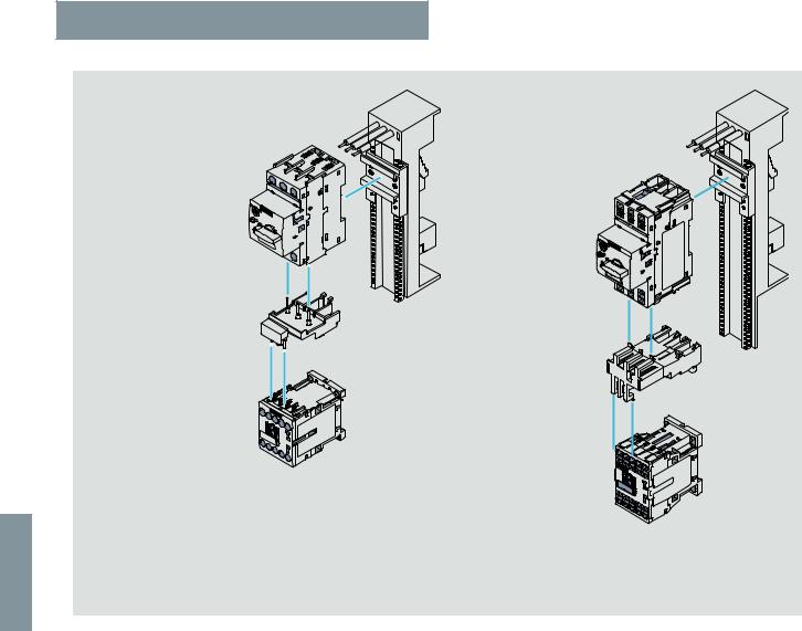
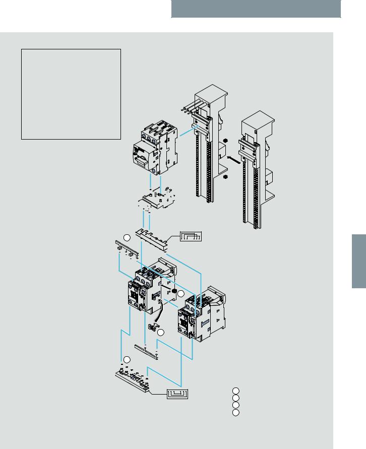
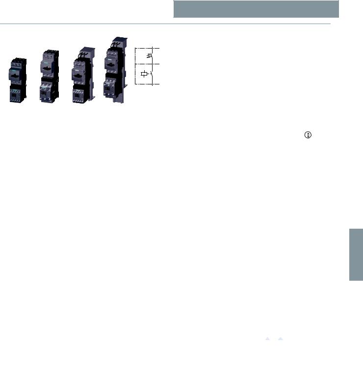
Direct-on-line starting • For standard rail mounting or screw fixing • Sizes S00 and S0 |
||
2 push-in lugs |
2 push-in lugs |
2 push-in lugs |
3RV29 28-0B |
3RV29 28-0B |
3RV29 28-0B |
(only for screw |
(only for screw |
(only for screw |
mounting) |
mounting) |
mounting) |
Motor starter protector |
Motor starter protector |
Motor starter protector |
Size S00/S0 |
Size S00/S0 |
Size S00/S0 |
Screw terminals |
Spring-type terminals |
Screw terminals |
Link module |
Link module |
Link module |
3RA19 21-1DA00 |
3RA29 11-2AA00 for S00 |
3RA29 11-2FA00 for S00 |
(for S00) |
3RA29 21-2AA00 for S0 |
3RA29 21-2FA00 for S0 |
3RA29 21-1AA00 |
|
|
(for S0, AC contactor) |
|
|
3RA29 21-1BA00 |
|
|
(for S0, DC contactor) |
|
|
Contactor |
Contactor |
Contactor |
Size S00/S0 |
Size S00/S0 |
Size S00/S0 |
Screw terminals |
Spring-type terminals |
Spring-type terminals |
|
|
NSB0_02089 |
Left: 3RA21 motor starter with screw connection
Center: 3RA21 motor starter with spring-type connection
Right: Motor starter protector combination with screw connection, with contactor with spring-type connection
2 push-in lugs |
2 push-in lugs |
3RV29 28-0B |
3RV29 28-0B |
(only for screw mounting) |
(only for screw mounting) |

 Motor starter protector
Size S00/S0
Screw terminals
Link module
3RA29 21-1BA00
Motor starter protector
Size S00/S0 Screw terminals/
spring-type terminals
Link module
3RA29 21-1BA00 for S00/S0 and screw terminals 3RA29 11-2GA00 for S00 and spring-type terminals 3RA29 21-2GA00 for S0 and spring-type terminals
Solid-state |
Soft starter |
switching device |
Size S00/S0 |
|
Screw terminals/ |
|
spring-type terminals |
|
NSB0_02090 |
Left: Motor starter protector combination with solid-state switching device with screw connection Right: Motor starter protector combination with soft starter with spring-type connection
6
SIRIUS Innovations Supplement 2011 |
6/5 |
|
|
6
© Siemens AG 2011
Combination Starters & Starters for Group Installation
SIRIUS 3RA2 Motor Starters
General data
Direct-on-line starting • For 60 mm busbar systems • Sizes S00 and S0
60 mm busbar adapter |
60 mm busbar adapter |
for screw terminals |
for spring-type terminals |
8US12 51-5DS10 for S00 |
8US12 51-5DT11 for S00 |
8US12 51-5NT10 for S0 |
8US12 51-5NT11 for S0 |
Motor starter protector |
|
Size S00/S0 |
|
Screw terminals |
|
|
Motor starter protector |
|
Size S00/S0 |
|
Spring-type terminals |
Link module |
|
3RA19 21-1DA00 for S00 |
|
3RA29 21-1AA00 for S0, AC contactor |
|
3RA29 21-1BA00 for S0, DC contactor |
|
|
Link module |
|
3RA29 11-2AA00 for S00 |
|
3RA29 21-2AA00 for S01) |
Contactor |
|
Size S00/S0 |
|
Screw terminals |
|
|
Contactor |
|
Size S00/S0 |
|
Spring-type terminals |
NSB0_02091a
1) Additional 3RA29 11-1CA00 spacer
for height compensation on AC contactors size S0 with spring-type terminals.
Left: 3RA21 motor starter for direct-on-line starting with busbar adapters with screw connection
Right: 3RA21 motor starter for direct-on-line starting with busbar adapters with spring-type connection
6/6 |
SIRIUS Innovations Supplement 2011 |
|
|
© Siemens AG 2011
Combination Starters & Starters for Group Installation
SIRIUS 3RA2 Motor Starters
General data
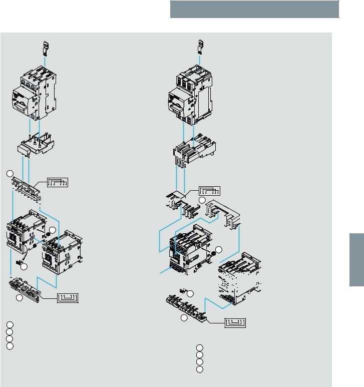
Reversing duty • For standard rail mounting or screw fixing • Size S00
2 push-in lugs
3RV29 28-0B
(only for screw mounting)
Motor starter protector
Size S00
Screw terminals
Link module
3RA19 21-1DA00 for S00
1
3
2 contactors
Size S00 Screw terminals
4
2
Wiring kit
3RA29 13-2AA1
1Upper wiring module
2Lower wiring module
32 connecting clips
4Mechanical interlock
(can be removed if necessary)
2 push-in lugs
3RV29 28-0B
(only for screw mounting)
Motor starter protector
Size S00 Spring-type terminals
Link module
3RA29 11-2AA00 for S00


 1
1
3


 02092a_NSB0

 4
4 


2
Wiring kit
3RA29 13-2AA2
1Upper wiring module
2Lower wiring module
32 connecting clips
4Mechanical interlock
(can be removed if necessary)
6
2 contactors
Size S00 Spring-type terminals
Left: 3RA22 motor starter with screw connection, push-in lugs, 2 contactors for reversing duty and 3RA29 13-2AA1 wiring kit for connecting the contactors (incl. mechanical interlocking and connecting clips)
Right: 3RA22 motor starter with spring-type connection, push-in lugs, 2 contactors for reversing duty and 3RA29 13-2AA2 wiring kit (incl. mechanical interlocking and connecting clips)
SIRIUS Innovations Supplement 2011 |
6/7 |
|
|
© Siemens AG 2011
Combination Starters & Starters for Group Installation
SIRIUS 3RA2 Motor Starters
General data
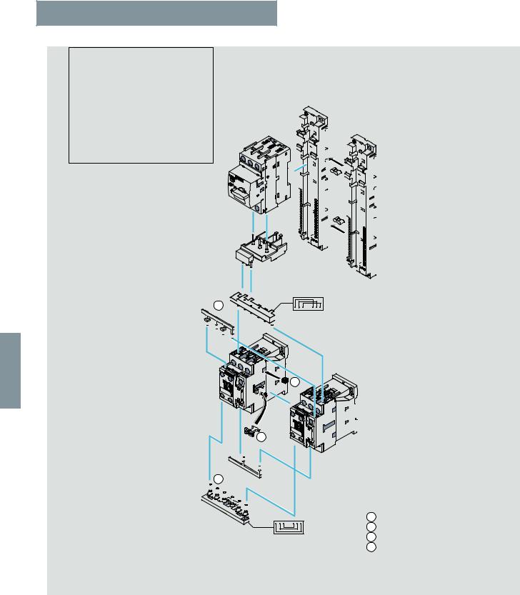
Reversing duty • For standard rail mounting • Size S0
RH assembly kit for reversing duty and standard rail mounting in size S0
For screw terminals: 3RA29 23-1BB1
For spring-type terminals: 3RA29 23-1BB21) Comprising:
1 wiring kit
2 standard mounting rail adapters
2 connecting wedges
1)Also includes 3RA29 11-1CA00 spacer for height compensation on AC contactors size S0 with spring-type terminals.
Motor starter protector
Size S0
Screw terminals/ spring-type terminals
Link module
For screw terminals: 3RA29 21-1AA00 (AC) 3RA29 21-1BA00 (DC)
For spring-type terminals: 3RA29 21-2AA002)
1
2 standard mounting rail adapters
3RA29 22-1AA00
with 2 connecting wedges 8US19 98-1AA00
6
3


 NSB0_02093b
4
2 contactors
Size S0
Screw terminals/ spring-type terminals
2
2)Additional 3RA29 11-1CA00 spacer
for height compensation on AC contactors size S0 with spring-type terminals
Wiring kit
For screw terminals: 3RA29 23-2AA1
For spring-type terminals: 3RA29 23-2AA2
1Upper wiring module
2Lower wiring module
32 connecting clips
4Mechanical interlock
(can be removed if necessary)
3RA22 motor starter for reversing duty and standard rail mounting in size S0 (the version with screw connection is shown in the picture)
6/8 |
SIRIUS Innovations Supplement 2011 |
|
|
© Siemens AG 2011
Combination Starters & Starters for Group Installation
SIRIUS 3RA2 Motor Starters
General data
Reversing duty • For 60 mm busbar systems • Sizes S00 and S0
RS assembly kit for reversing duty and busbar mounting
Screw connection: 3RA29 13-1DB1 for S00 3RA29 23-1DB1 for S0
For spring-type connection: 3RA29 13-1DB2 for S00 3RA29 23-1DB2 for S01)
Comprising: 1 wiring kit
1 busbar adapter
1 device holder
2 connecting wedges
1)Also includes 3RA29 11-1CA00 spacer for height compensation on AC contactors size S0 with spring-type terminals.
Motor starter protector
Size S00/S0 Screw terminals/
spring-type terminals
Link module
For screw terminals: 


 3RA19 21-1DA00 for S00


 3RA29 21-1AA00 for S0, AC contactor


 3RA29 21-1BA00 for S0, DC contactor


 For spring-type terminals:
3RA29 11-2AA00 for S00 3RA29 21-2AA00 for S02)
1
60 mm busbar adapter
For screw terminals: 8US12 51-5DS10 for S00 8US12 51-5NT10 for S0 For spring-type terminals: 8US12 51-5DT11 for S00 8US12 51-5NT11 for S0
2 connecting wedges
8US19 98-1AA00
60 mm device holder
8US12 51-5AS10
6
2)Additional 3RA29 11-1CA00 spacer
for height compensation on AC contactors size S0 with spring-type terminals.
3 |
|
|
2 contactors |
02094b |
Size S00/S0 |
spring-type terminals |
|
|
Screw terminals/ |
NSB0 |
|
4
|
Wiring kit |
||
2 |
Screw connection: |
||
3RA29 13-2AA1 for S00 |
|||
|
|||
|
3RA29 23-2AA1 for S0 |
||
|
Spring-type connection: |
||
|
3RA29 13-2AA2 for S00 |
||
|
3RA29 23-2AA2 for S0 |
||
|
1 |
Upper wiring module |
|
|
2 |
Lower wiring module |
|
|
3 |
2 connecting clips |
|
|
4 |
Mechanical interlock |
|
|
|
(can be removed if necessary) |
|
3RA22 motor starter for reversing duty and 60 mm standard mounting rail in size S00/S0 (the version with screw connection is shown in the picture)
SIRIUS Innovations Supplement 2011 |
6/9 |
|
|

6
© Siemens AG 2011
Combination Starters & Starters for Group Installation
SIRIUS 3RA2 Motor Starters
General data
Order No. scheme
Digit of the Order No. |
1st - |
4th |
5th |
6th |
7th |
|
8th |
9th |
10th |
11th |
12th |
|
13th |
14th |
15th |
16th |
|
|
3rd |
|
|
|
|
|
|
|
|
|
|
|
|
|
|
|
|
|
@@@ |
@ |
@ |
@ |
0 |
– |
@ |
@ |
@ |
@ |
@ |
– |
@ |
@ |
@ |
@ |
|
SIRIUS starters |
3 R A |
|
|
|
|
|
|
|
|
|
|
|
|
|
|
|
|
SIRIUS 2nd generation |
|
2 |
|
|
|
|
|
|
|
|
|
|
|
|
|
|
|
Type of starter (direct-on-line starter = 1, |
|
|
@ |
|
|
|
|
|
|
|
|
|
|
|
|
|
|
reversing starter = 2) |
|
|
|
|
|
|
|
|
|
|
|
|
|
|
|
|
|
Size (S00 = 1, S0 = 2) |
|
|
|
@ |
|
|
|
|
|
|
|
|
|
|
|
|
|
Setting range for overload release |
|
|
|
|
|
|
@ |
@ |
|
|
|
|
|
|
|
|
|
Design type and connection method |
|
|
|
|
|
|
|
|
@ |
|
|
|
|
|
|
|
|
Rated power at 460 V AC |
|
|
|
|
|
|
|
|
|
@ |
@ |
|
|
|
|
|
|
Integrated auxiliary switches of the contactor |
|
|
|
|
|
|
|
|
|
|
|
|
@ |
|
|
|
|
Operating range / solenoid coil circuit (contactor) |
|
|
|
|
|
|
|
|
|
|
|
|
|
@ |
|
|
|
Rated control supply voltage (contactor) |
|
|
|
|
|
|
|
|
|
|
|
|
|
|
@ |
@ |
|
Example |
3 R A |
2 |
1 |
1 |
0 |
– |
0 |
B |
A |
1 |
5 |
– |
1 |
A |
K |
6 |
|
|
|
|
|
|
|
|
|
|
|
|
|
|
|
|
|
|
|
Note:
The Order No. scheme is presented here merely for information purposes and for better understanding of the logic behind the order numbers.
For your orders, please use the order numbers quote in the catalog in the Selection and ordering data.
■ Technical specifications
Direct-on-line starters/ |
Size |
Connection methods |
Mounting |
|
|
|
Control voltage |
|
|
Width W |
Height H |
Depth D |
||||||||||||||||||
reversing starters |
|
|
|
|
|
|
|
|
|
|
|
|
|
|
|
|
|
|
|
|
|
|||||||||
|
|
|
|
|
|
|
|
|
|
|
|
|
|
|
|
|
|
|
|
|
|
|
|
|
|
|
mm |
mm |
mm |
|
|
|
|
|
|
|
|
|
|
|
|
|
|
|
|
|
|
|
|
|
|
|
|
|
|
|
|
|
|
|
|
Mounting dimensions |
|
|
|
|
|
|
|
|
|
|
|
|
|
|
|
|
|
|
|
|
|
|||||||||
|
|
|
|
|
|
|
|
|
|
|
|
|
|
|
|
|
|
|
|
|
|
|
|
|
|
|
|
|
|
|
Direct-on-line starters |
S00 |
Screw terminals |
|
Standard mounting rails |
|
AC/DC |
|
|
45 |
167 |
97 |
|
||||||||||||||||||
3RA21. |
|
|
|
3RA21 1. |
|
|
Busbar adapters |
|
|
|
AC/DC |
|
|
45 |
200 |
155 |
|
|||||||||||||
|
|
|
|
|
|
|
|
|
|
|
Spring-type terminals |
Standard mounting rails |
|
AC/DC |
|
|
45 |
198 |
97 |
|
||||||||||
|
|
|
|
|
|
|
|
|
|
|
|
|
Busbar adapters |
|
|
|
AC/DC |
|
|
45 |
260 |
155 |
|
|||||||
|
|
|
|
|
|
|
|
|
|
S0 |
Screw terminals |
|
Standard mounting rails |
|
AC |
|
|
45 |
193 |
97 |
|
|||||||||
H |
|
|
|
|
|
|
|
|
3RA21 2. |
|
|
|
|
|
|
|
|
|
|
DC |
|
|
45 |
193 |
107 |
|
||||
|
|
|
|
|
|
|
|
|
|
|
|
|
|
|
|
|
|
|
|
|||||||||||
|
|
|
|
|
|
|
|
|
|
|
|
|
|
|
|
|
|
|
|
|
|
|
|
|
|
|
|
|
|
|
|
|
|
|
|
|
|
D |
|
|
|
Busbar adapters |
|
|
|
AC |
|
|
45 |
260 |
155 |
|
|||||||||
|
|
|
|
|
W |
|
|
|
|
|
|
|
|
|||||||||||||||||
|
|
|
|
|
|
|
|
|
|
|
|
|
|
|
|
|
|
|
DC |
|
|
45 |
260 |
165 |
|
|||||
|
|
|
|
|
|
|
|
|
|
|
|
|
|
|
|
|
|
|
|
|
|
|
|
|||||||
|
|
|
|
|
|
|
|
|
|
|
Spring-type terminals |
Standard mounting rails |
|
AC/DC |
|
|
45 |
243 |
107 |
|
||||||||||
|
|
|
|
|
|
|
|
|
|
|
|
|
Busbar adapters |
|
|
|
AC/DC |
|
|
45 |
260 |
165 |
|
|||||||
Reversing starters |
S00 |
Screw terminals |
|
Standard mounting rails |
|
AC/DC |
|
|
90 |
170 |
97 |
|
||||||||||||||||||
3RA22. |
|
|
|
3RA22 1. |
|
|
Busbar adapters |
|
|
|
AC/DC |
|
|
90 |
200 |
155 |
|
|||||||||||||
|
|
|
|
|
|
|
|
|
|
|
Spring-type terminals |
Standard mounting rails |
|
AC/DC |
|
|
90 |
204 |
97 |
|
||||||||||
|
|
|
|
|
|
|
|
|
|
|
|
|
Busbar adapters |
|
|
|
AC/DC |
|
|
90 |
260 |
155 |
|
|||||||
|
|
|
|
|
|
|
|
|
|
S0 |
Screw terminals |
|
Standard mounting rail |
|
AC |
|
|
90 |
265 |
120.3 |
|
|||||||||
|
|
|
|
|
|
|
|
|
|
3RA22 2. |
|
|
adapters |
|
|
|
DC |
|
|
90 |
265 |
130 |
|
|||||||
|
|
|
|
|
|
|
|
|
|
|
|
|
|
|
|
|
|
|
|
|
|
|
||||||||
|
|
|
|
|
|
|
|
|
|
|
|
|
Busbar adapters |
|
|
|
AC |
|
|
90 |
260 |
155 |
|
|||||||
|
|
|
|
|
|
|
|
|
|
|
|
|
|
|
|
|
|
|
|
|
DC |
|
|
90 |
260 |
165 |
|
|||
|
|
|
|
|
|
|
|
|
|
|
Spring-type terminals |
Standard mounting rail |
|
AC/DC |
|
|
90 |
270 |
131 |
|
||||||||||
|
|
|
|
|
|
|
|
|
|
|
|
|
adapters |
|
|
|
|
|
|
|
|
|
|
|
|
|
||||
|
|
|
|
|
|
|
|
|
|
|
|
|
Busbar adapters |
|
|
|
AC/DC |
|
|
90 |
260 |
165 |
|
|||||||
|
|
|
|
|
|
|
|
|
|
|
|
|
|
|
|
|
|
|
|
|
|
|
|
|||||||
Type |
|
|
|
|
|
|
|
3RA2. 1 |
|
|
|
|
|
|
|
|
3RA2. 2 |
|
|
|
||||||||||
|
|
|
|
|
|
|
|
|
|
|
|
|
|
|
|
|
|
|||||||||||||
Size |
|
|
|
|
|
|
|
|
|
|
|
|
|
|
|
|
|
|
|
|
|
|
|
|||||||
|
|
|
|
|
|
|
S00 |
|
|
|
|
|
|
|
|
S0 |
|
|
|
|||||||||||
Number of poles |
|
|
|
|
|
|
|
|
|
|
|
|
|
|
|
|
|
|
|
|
|
|||||||||
|
|
|
|
3 |
|
|
|
|
|
|
|
|
|
|
3 |
|
|
|
|
|||||||||||
Mechanics and environment |
|
|
|
|
|
|
|
|
|
|
|
|
|
|
|
|
|
|
|
|
||||||||||
|
|
|
|
|
|
|
|
|
|
|
|
|
|
|
|
|
|
|
|
|
||||||||||
Permissible ambient temperature |
|
|
|
|
|
|
|
|
|
|
|
|
|
|
|
|
|
|
|
|
||||||||||
• During operation |
|
|
°C |
|
|
|
|
|
|
|
|
|
|
|
|
|
|
|
|
|
|
|||||||||
|
|
|
-20 ... +60 |
|
|
|
|
|
|
|
|
|
|
|
|
|
|
|
||||||||||||
• Storage and transport |
|
|
°C |
|
|
|
|
|
|
|
|
|
|
|
|
|
|
|
|
|
|
|||||||||
|
|
|
-55 ... +80 |
|
|
|
|
|
|
|
|
|
|
|
|
|
|
|
||||||||||||
Weight |
|
|
|
|
|
kg |
|
0.6 ... 1.5 |
|
|
|
|
|
|
|
|
|
0.8 ... 2.3 |
|
|
|
|||||||||
Permissible mounting |
|
|
|
|
|
|
|
|
|
|
22,5° |
22,5° |
|
|
|
|
|
|
||||||||||||
positions |
|
|
|
|
|
|
|
90° |
|
|
90° |
|
|
|
|
|
|
|
||||||||||||
|
|
|
|
|
|
|
|
|
|
|
|
|
|
NSB00369 |
|
|
|
|
|
|
||||||||||
|
|
|
|
|
|
|
|
|
|
|
|
|
|
|
|
|
|
|
|
|
|
|
|
|
|
|
||||
|
|
|
|
|
|
|
|
|
|
|
|
|
|
|
|
|
|
|
|
|
|
|
|
|
|
|
|
|
|
|
|
|
|
|
|
|
|
|
|
|
|
|
|
|
|
|
|
|
|
|
|
|
|
|
|
|
|
|
|
|
|
|
|
|
|
|
|
|
|
|
|
|
|
|
|
|
|
|
|
|
|
|
|
|
|
|
|
|
|
|
|
|
|
|
|
|
|
|
|
|
|
|
|
|
|
|
Important: Acc. to DIN 43602 start command "I" at the right or top |
|
|
||||||||||||||
Shock resistance |
Acc. to IEC 60086 Part 2-27 |
g |
|
Up to 6 |
|
|
|
|
|
|
|
|
Up to 6 |
|
|
|
||||||||||||||
(sine-wave pulse) |
|
|
|
|
|
|
|
|
|
|
|
|
|
|
|
|
|
|
|
|
|
|||||||||
Degree of protection |
Acc. to IEC 60947-1 |
|
|
IP20 |
|
|
|
|
|
|
|
|
|
|
|
|
|
|||||||||||||
|
|
|
|
|
|
|
|
|
|
|
|
|
|
|
|
|
|
|
|
|
|
|
|
|
|
|
|
|
|
|
6/10 |
SIRIUS Innovations Supplement 2011 |
|
|
© Siemens AG 2011
Combination Starters & Starters for Group Installation
|
|
|
|
|
|
|
SIRIUS 3RA2 Motor Starters |
|
|
|||
|
|
|
|
|
|
|
|
General data |
|
|
||
|
|
|
|
|
|
|
|
|
|
|
|
|
|
■ More information |
|
|
|
|
|
|
|
|
|
|
|
|
|
|
|
|
|
|
|
|
|
|
||
|
|
Type |
|
|
3RA2. 1 |
|
3RA2. 2 |
|
|
|
||
|
|
Size |
|
|
S00 |
|
S0 |
|
|
|
||
|
|
Number of poles |
|
|
3 |
|
|
3 |
|
|
|
|
|
|
General data |
|
|
|
|
|
|
|
|
|
|
|
|
Standards |
|
|
IEC 60947-1, EN 60947-1 |
|
|
|
|
|
|
|
|
|
|
|
|
IEC 60947-2, EN 60947-2 |
|
|
|
|
|
|
|
|
|
|
|
|
IEC 60947-4-1, EN 60947-4-1 |
|
|
|
|
|
|
|
|
|
Max. rated current In max (= max. rated operational current Ie) |
A |
16 |
|
|
32 |
|
|
|
|
|
|
|
Permissible ambient temperature |
°C |
-20 ... +60 for operation |
|
|
|
|
|
|
||
|
|
|
|
°C |
|
|
|
|
||||
|
|
|
|
-55 ... +80 during storage/transport |
|
|
|
|
||||
|
|
Rated operational voltage Ue |
|
V |
690 |
|
|
|
|
|
|
|
|
|
Rated frequency |
|
Hz |
50/60 |
|
|
|
|
|
|
|
|
|
Rated insulation voltage Ui (pollution degree 3) |
V |
690 |
|
|
|
|
|
|
|
|
|
|
Rated impulse withstand voltage Uimp |
kV |
6 |
|
|
|
|
|
|
|
|
|
|
Trip class (CLASS) |
Acc. to IEC 60947-4-1, |
|
10 |
|
|
|
|
|
|
|
|
|
|
EN 60947-4-1 |
|
|
|
|
|
|
|
|
|
|
|
Rated short-circuit current Iq at AC 50/60 Hz 400 V |
kA |
153 |
|
|
|
|
|
|
|
|
|
|
acc. to IEC 60947-4-1, EN 60947-4-1 |
|
|
|
|
|
|
|
|
|
|
|
|
Power loss Pv max of all main |
Up to 1.25 A |
W |
2 |
|
|
-- |
|
|
|
|
|
|
|
|
|
|
|
|
|
||||
|
|
current paths |
1.6 ... 6.3 A |
W |
2.3 |
|
|
-- |
|
|
|
|
|
|
Dependent on the rated current |
8 ... 12 A |
W |
3.5 |
|
|
-- |
|
|
|
|
|
|
In |
16 A |
W |
|
|
|
|
|
|
|
|
|
|
4.3 |
|
|
-- |
|
|
|
|
|||
|
|
(upper setting range) |
5 ... 6.3 A |
W |
|
|
|
|
|
|
|
|
|
|
-- |
|
|
2.3 |
|
|
|
|
|||
|
|
|
8 ... 12 A |
W |
-- |
|
|
3.5 |
|
|
|
|
|
|
|
16 ... 32 A |
W |
|
|
|
|
|
|
|
|
|
|
|
-- |
|
|
4.3 |
|
|
|
|
||
|
|
Power consumption of the solenoid coils for contactors |
|
|
|
|
|
|
|
|
|
|
|
|
as a function of the standard output P of the motor |
|
|
|
|
|
|
|
|
|
|
|
|
(when coil is cold and Us’ 50 Hz) |
|
|
|
|
|
|
|
|
|
|
|
|
• AC operation |
|
|
|
|
|
|
|
|
|
|
|
|
- Closing |
Up to 4 kW |
VA |
|
|
|
|
|
|
|
|
|
|
27 |
|
|
-- |
|
|
|
|
|||
|
|
|
5.5 ... 7.5 kW |
VA |
37 |
|
|
-- |
|
|
|
|
|
|
|
Up to 5.5 kW |
VA |
|
|
|
|
|
|
|
|
|
|
|
-- |
|
|
65 |
|
|
|
|
||
|
|
|
7.5 ... 15 kW |
VA |
|
|
|
|
|
|
|
|
|
|
|
-- |
|
|
77 |
|
|
|
|
||
|
|
|
P.f. |
|
0.8 |
|
|
0.82 |
|
|
|
|
|
|
|
|
|
|
|
||||||
|
|
- Closed |
Up to 4 kW |
VA |
|
|
|
|
|
|
|
|
|
|
4.2 |
|
|
-- |
|
|
|
|
|||
|
|
|
5.5 ... 7.5 kW |
VA |
|
|
|
|
|
|
|
|
|
|
|
5.7 |
|
|
-- |
|
|
|
|
||
|
|
|
Up to 5.5 kW |
VA |
-- |
|
|
8.5 |
|
|
|
|
|
|
|
7.5 ... 15 kW |
VA |
|
|
|
|
|
|
|
|
|
|
|
-- |
|
|
9.8 |
|
|
|
6 |
||
|
|
|
P.f. |
|
0.25 |
|
|
0.25 |
|
|
|
|
|
|
|
|
|
|
|
|
|
|
|
|
|
|
|
• DC operation |
Closing = |
W |
4 |
|
|
5.9 |
|
|
|
|
|
|
|
Closed |
|
|
|
|
|
|
|
|
|
|
|
Solenoid coil operating range for contactors |
|
0.8 ... 1.1 x Us |
|
|
|
|
|
|
||
|
|
|
Lower limit at 55 °C |
|
0.8 x Us |
|
-- |
|
|
|
|
|
|
|
|
|
|
|
|||||||
|
|
|
At 60 °C |
|
0.85 x Us |
|
-- |
|
|
|
|
|
|
|
Endurance of the motor starter protector |
|
|
|
|
|
|
|
|
|
|
|
|
|
|
|
|
|
|
|
|
|
|
|
|
|
• Mechanical endurance |
Operating cycles |
|
100000 |
|
|
|
|
|
|
|
|
|
|
|
|
|
|
|
|
|
|
|
|
|
|
• Electrical endurance |
Operating cycles |
|
100000 |
|
|
|
|
|
|
|
|
|
• Max. switching frequency per hour (motor starts) |
1/h |
15 |
|
|
|
|
|
|
|
|
|
|
Endurance of contactor |
|
|
|
|
|
|
|
|
|
|
|
|
• Mechanical endurance |
Operating cycles |
|
30 million |
|
10 million |
|
|
|
||
|
|
• Electrical endurance |
Operating cycles |
|
|
|
|
|
|
|||
|
|
|
See endurance characteristic curves of the contactors --> |
|
|
|
||||||
|
|
|
|
|
Chapter 3 "Controls – Contactors and Contactor Assemblies" |
|
|
|
||||
|
|
Shock resistance (sine-wave |
Acc. to IEC 60086 Part 2-27 |
g |
Up to 6 |
|
Up to 6 |
|
|
|
|
|
|
|
pulse) |
|
|
|
|
|
|
|
|
|
|
|
|
Degree of protection |
Acc. to IEC 60947-1 |
|
IP20 |
|
|
|
|
|
|
|
|
|
Touch protection |
Acc. to EN 50274 |
|
Finger-safe |
|
|
|
|
|
|
|
|
|
Phase failure sensitivity |
Acc. to IEC 60947-1, |
|
Yes |
|
|
|
|
|
|
|
|
|
of the motor starter protector |
EN 60947-1 |
|
|
|
|
|
|
|
|
|
|
|
Isolating features |
Acc. to IEC 60947-2, |
|
Yes |
|
|
|
|
|
|
|
|
|
of the motor starter protector |
EN 60947-2 |
|
|
|
|
|
|
|
|
|
|
|
Main control and EMER- |
Acc. to IEC 60204-1, |
|
Yes |
|
|
|
|
|
|
|
|
|
GENCY-STOP switch charac- |
EN 60204-1 |
|
(with overvoltage releases of category "1" under conditions of proper use) |
|
|
|
||||
|
|
teristics of the motor starter |
|
|
|
|
|
|
|
|
|
|
|
|
protector and accessories |
|
|
|
|
|
|
|
|
|
|
|
|
Protective separation between |
Acc. to EN 60947-1, |
V |
Up to 400 |
|
|
|
|
|
|
|
|
|
main and auxiliary circuits |
Appendix N |
|
|
|
|
|
|
|
|
|
|
|
Mirror contacts for contactors |
|
|
Yes |
|
Yes, from main contact to auxiliary |
|
|
|
|
|
|
|
|
|
|
|
|
|
NC contact |
|
|
|
|
|
|
|
|
|
|
|
|
|
|
|
|
|
SIRIUS Innovations Supplement 2011 |
6/11 |
|
|

© Siemens AG 2011
Combination Starters & Starters for Group Installation
SIRIUS 3RA2 Motor Starters
General data
Type |
SIRIUS 3RA2 Motor Starters |
|
|
|
|||
Connection type |
|
|
|
Screw terminals |
|
|
Spring-type terminals |
|
|
|
|
|
|
|
|
|
|
|
|
|
|
|
|
Conductor cross-sections for main conductors
Size S00
|
|
|
|
Motor starter protectors, contactors |
Motor starter protectors, contactors |
|||
|
|
Terminal screw |
|
M3, Pozidriv size 2 |
-- |
|
||
|
|
Operating devices |
mm |
! 5 ... 6 |
|
|
3.0 x 0.5 and 3.5 x 0.5 |
|
|
|
Prescribed tightening torque |
Nm |
0.8 ... 1.2 |
|
|
-- |
|
|
|
Conductor cross-sections (min./max.), |
|
|
|
|
|
|
|
|
1 or 2 conductors can be connected |
|
|
|
|
|
|
|
|
• Solid and stranded |
mm2 |
2 x (0.5 … 1.5)1) only for contactors, |
|
|
||
|
|
|
mm2 |
2 x (0.75 ... 2.5)1), |
|
|
||
|
|
|
2 x (0.5 ... 4) |
|
||||
|
|
|
mm2 |
|
|
|
|
|
|
|
|
max. 2 x 4 |
|
|
|
|
|
|
|
|
mm2 |
|
|
|
|
|
|
|
• Finely stranded without end sleeve |
-- |
|
|
2 x (0.5 ... 2.5) |
|
|
|
|
• Finely stranded with end sleeves (DIN 46 228 T1) mm2 |
|
|
|
|
|
|
|
2 x (0.5 ... 1.5)1). |
2 x (0.5 ... 2.5) |
|
|||||
|
|
|
mm2 |
2 x (0.75 ... 2.5)1) |
|
|
||
|
|
|
|
|
||||
|
|
|
|
|
|
|
|
|
|
|
• AWG cables, solid or stranded |
AWG |
2 x (20 … 16)1) only for contactors, |
|
|
||
|
|
|
AWG |
2 x (18 ... 14)1), |
|
|
|
|
|
|
|
|
2 x (20 ... 12) |
|
|||
|
|
|
AWG |
|
|
|
|
|
|
|
|
2 x 12 |
|
|
|
|
|
|
|
Max. external diameter of the conductor insulation |
mm |
-- |
|
|
3.6 |
|
|
|
Conductor cross-sections for main conductors |
|
|
|
|
|
|
|
|
Size S0 |
|
|
|
|
|
|
|
|
|
|
|
|
|
||
|
|
|
|
Motor starter protectors, contactors |
Motor starter protectors, contactors |
|||
|
|
Terminal screw |
|
M4, Pozidriv size 2 |
-- |
|
||
|
|
Operating devices |
mm |
! 5 ... 6 |
|
|
3.0 x 0.5 and 3.5 x 0.5 |
|
|
|
Prescribed tightening torque |
Nm |
2.0 ... 2.5 |
|
|
-- |
|
|
|
Conductor cross-sections (min./max.), |
|
|
|
|
|
|
|
|
1 or 2 conductors can be connected |
|
|
|
|
|
|
|
|
• Solid and stranded |
mm2 |
2 x (1.0 ... 2.5)1), |
2 x (1.0 ... 10) |
|
||
|
|
|
mm2 |
2 x (2.5 ... 10)1) |
|
|
|
|
|
|
|
|
|
|
|||
|
|
• Finely stranded without end sleeve |
mm2 |
-- |
|
|
2 x (1.0 ... 6.0) |
|
|
|
|
|
|
||||
6 |
|
|
|
|
|
|
|
|
|
|
2 |
2 x (1.0 ... 2.5) |
1) |
, |
2 x (1.0 ... 6.0) |
|
|
|
|
• Finely stranded with end sleeves (DIN 46 228 T1) mm |
|
|
||||
|
|
|
mm2 |
2 x (2.5 ... 6)1) |
|
|
|
|
|
|
|
mm2 |
|
|
|
|
|
|
|
|
max. 1 x 10 |
|
|
|
|
|
|
|
|
|
|
|
|
|
|
|
|
• AWG cables, solid or stranded |
AWG |
2 x (16 ... 12)1), |
|
2 x (18 ... 8) |
|
|
|
|
|
AWG |
2 x (14 ... 8)1) |
|
|
|
|
|
|
|
|
|
|
|
||
|
|
Max. external diameter of the conductor insulation |
mm |
-- |
|
|
3.6 |
|
|
|
Conductor cross-sections for auxiliary |
|
|
|
|
|
|
|
|
conductors, Size S00/S0 |
|
|
|
|
|
|
|
|
|
|
Contactors (basic unit), |
Contactors S00 |
Contactors S0, |
||
|
|
|
|
motor starter protectors (accessories), |
|
motor starter protec- |
||
|
|
|
|
contactors (mountable accessories), |
|
tors (accessories), |
||
|
|
|
|
overload relays |
|
contactors |
||
|
|
|
|
|
|
|
|
(accessories), |
|
|
|
|
|
|
|
|
overload relays |
|
|
Terminal screw |
|
M3, Pozidriv size 2 |
-- |
|
||
|
|
Operating devices |
mm |
! 5 ... 6 |
|
|
3.0 x 0.5 and 3.5 x 0.5 |
|
|
|
Prescribed tightening torque |
Nm |
0.8 ... 1.2 |
|
|
-- |
|
|
|
Conductor cross-sections (min./max.), |
|
|
|
|
|
|
|
|
1 or 2 conductors can be connected |
|
|
|
|
|
|
|
|
• Solid and stranded |
mm2 |
2 x (0.5 ... 1.5)1), |
2 x (0.5 ... 4) |
2 x (0.5 ... 2.5) |
||
|
|
|
mm2 |
2 x (0.75 ... 2.5)1), |
|
|
||
|
|
|
|
|
||||
|
|
|
mm2 |
|
|
|
||
|
|
|
max. 2 x 4 only for contactors S00 |
|
|
|||
|
|
• Finely stranded without end sleeve |
mm2 |
-- |
|
|
2 x (0.5 ... 2.5) |
2 x (0.5 ... 1.5) |
|
|
|
|
|||||
|
|
|
mm2 |
|
|
|
|
|
|
|
• Finely stranded with end sleeve |
2 x (0.5 ... 1.5)1), |
2 x (0.5 ... 2.5) |
2 x (0.5 ... 1.5) |
|||
|
|
|
mm2 |
2 x (0.75 ... 2.5)1) |
|
|
||
|
|
|
|
|
||||
|
|
|
|
|
|
|
|
|
|
|
• AWG cables, solid or stranded |
AWG |
2 x (20 ... 16)1), |
|
2 x (20 ... 12) |
2 x (20 ... 14) |
|
|
|
|
AWG |
2 x (18 ... 14)1), |
|
|
|
|
|
|
|
|
|
|
|||
|
|
|
AWG |
|
|
|
||
|
|
|
2 x 12 only for contactors S00 |
|
|
|||
|
|
Max. external diameter of the conductor insulation |
mm |
-- |
|
|
3.6 |
3.6 |
|
|
|
|
|||||
|
|
|
|
|
|
|
|
|
1)If two different conductor cross-sections are connected to one clamping point, both cross-sections must lie in the range specified. If identical crosssections are used, this restriction does not apply.
6/12 |
SIRIUS Innovations Supplement 2011 |
|
|
© Siemens AG 2011
Combination Starters & Starters for Group Installation
SIRIUS 3RA2 Motor Starters
3RA21 direct-on-line starters 50/60 Hz 110/120 V AC
■ Selection and ordering data
Direct-on-line starting
3RA21 10 |
3RA21 20 |
3RA21 10 |
3RA21 20 |
Rated control supply voltage 50/60 Hz 110/120 V AC With screw connections
•The motor starter protector and contactor are mechanically and electrically connected by means of the link module.
•Auxiliary switches1) on the motor starter protector and the contactor can be easily fitted due to the modular system.
•Integrated auxiliary switches:
-Contactor size S00: 1 NO;
-Contactor size S0: 1 NO + 1 NC
Combination Starter, UL508 Type F
All size S00 and S0 devices can be applied as Combination Starters with the addition of either of these line side connectors: 3RV29 28-1H, 3RV29 25-5EB or 3RV29 28-1K.
Size |
UL Data |
|
|
|
|
|
|
FLA setting |
Consisting of the following single |
|
Assembled starter |
|
|
|
|
Weight |
||||||||||||||||
|
|
|
|
|
|
|
|
|
|
range inverse- |
devices |
|
|
|
|
|
|
|
|
|
|
|
|
approx. |
||||||||
|
Single-phase |
|
Three-phase2) |
|
|
SCCR |
time delayed |
Motor |
+ Contactor |
+ Link |
|
Screw terminals |
|
|
|
|
|
|||||||||||||||
|
HP ratings |
|
HP ratings |
|
|
at |
overload |
starter |
|
module |
|
|
|
|
|
|
|
|
|
|
|
|||||||||||
|
|
|
|
release |
|
|
|
|
|
|
|
|
|
|
|
|
||||||||||||||||
|
|
|
|
|
|
|
|
|
480 V |
protector |
|
+ Busbar |
|
|
|
|
|
|
|
|
|
|
|
|||||||||
|
115 V |
230 V |
|
200 V |
230 V |
|
460 V |
575 V |
|
|
|
|
|
|
|
|
|
|
|
|
adapter3) |
|
Order No. |
|
|
|
|
|
|
|
||
|
|
|
|
|
|
|
|
|
kA |
A |
|
|
|
|
|
|
|
|
|
|
|
|
|
|
|
kg |
||||||
Selection depends on motor full load amps |
|
|
|
|
|
|
|
|
|
|
|
|
|
|
|
|
|
|
|
|
|
|
|
|||||||||
|
|
|
|
|
|
|
|
|
|
|
|
|
|
|
|
|
|
|
3RV20 |
3RT20 |
3RA |
|
|
|
|
|
|
|
|
|
|
|
S00 |
-- |
-- |
|
-- |
-- |
|
-- |
-- |
65 |
0.14…0.2 |
11-0BA10 15-1AK61 |
1921-1DA00 |
|
3RA21 10-0B@15-1AK6 |
|
|
|
|
0.575 |
|||||||||||||
|
-- |
-- |
|
-- |
-- |
|
-- |
-- |
65 |
0.18…0.25 |
11-0CA10 |
|
+ 8US1251- |
|
3RA21 10-0C@15-1AK6 |
|
|
|
|
0.575 |
||||||||||||
|
-- |
-- |
|
-- |
-- |
|
-- |
-- |
65 |
0.22…0.32 |
11-0DA10 |
|
5DS10 |
|
|
|
|
|
|
0.575 |
||||||||||||
|
|
|
|
|
3RA21 10-0D@15-1AK6 |
|
|
|
|
|||||||||||||||||||||||
|
-- |
-- |
|
-- |
-- |
|
-- |
-- |
65 |
0.28…0.4 |
11-0EA10 |
|
|
|
3RA21 10-0E@15-1AK6 |
|
|
|
|
0.575 |
||||||||||||
|
-- |
-- |
|
-- |
-- |
|
-- |
-- |
65 |
0.35…0.5 |
11-0FA10 |
|
|
|
|
|
|
|
|
0.575 |
||||||||||||
|
|
|
|
|
|
3RA21 10-0F@15-1AK6 |
|
|
|
|
||||||||||||||||||||||
|
-- |
-- |
|
-- |
-- |
|
-- |
-- |
65 |
0.45…0.63 |
11-0GA10 |
|
|
|
3RA21 10-0G@15-1AK6 |
|
|
|
|
0.575 |
||||||||||||
|
-- |
-- |
|
-- |
-- |
|
-- |
-- |
65 |
0.55…0.8 |
11-0HA10 |
|
|
|
3RA21 10-0H@15-1AK6 |
|
|
|
|
0.575 |
||||||||||||
|
-- |
-- |
|
-- |
-- |
|
-- |
1/2 |
65 |
0.7… |
1 |
11-0JA10 |
|
|
|
|
|
|
|
|
0.575 |
|||||||||||
|
|
|
|
|
|
3RA21 10-0J@15-1AK6 |
|
|
|
|
||||||||||||||||||||||
|
-- |
-- |
|
-- |
-- |
|
1/2 |
1/2 |
65 |
0.9… |
1.25 |
11-0KA10 |
|
|
|
|
|
|
|
|
0.575 |
|||||||||||
|
|
|
|
|
|
3RA21 10-0K@15-1AK6 |
|
|
|
|
||||||||||||||||||||||
|
-- |
1/10 |
|
-- |
-- |
|
3/4 |
3/4 |
65 |
1.1… |
1.6 |
11-1AA10 |
|
|
|
3RA21 10-1A@15-1AK6 |
|
|
|
|
0.575 |
|||||||||||
|
-- |
1/8 |
|
-- |
-- |
|
3/4 |
1 |
65 |
1.4… |
2 |
11-1BA10 |
|
|
|
|
|
|
|
|
|
|||||||||||
|
|
|
|
|
|
3RA21 10-1B@15-1AK6 |
|
|
|
|
0.575 |
|||||||||||||||||||||
|
-- |
1/6 |
|
1/2 |
1/2 |
|
1 |
1 1/2 |
65 |
1.8… |
2.5 |
11-1CA10 |
|
|
|
|
|
|
|
|
0.575 |
|||||||||||
|
|
|
|
|
|
3RA21 10-1C@15-1AK6 |
|
|
|
|
||||||||||||||||||||||
|
1/10 |
1/4 |
|
1/2 |
3/4 |
|
1 1/2 |
2 |
65 |
2.2… 3.2 |
11-1DA10 |
|
|
|
3RA21 10-1D@15-1AK6 |
|
|
|
|
0.575 |
||||||||||||
|
1/8 |
1/3 |
|
3/4 |
3/4 |
|
2 |
3 |
65 |
2.8… 4 |
11-1EA10 |
|
|
|
|
|
|
|
|
0.575 |
||||||||||||
|
|
|
|
|
|
3RA21 10-1E@15-1AK6 |
|
|
|
|
||||||||||||||||||||||
|
1/6 |
1/2 |
|
1 |
1 |
|
3 |
3 |
65 |
3.5… 5 |
11-1FA10 |
|
|
|
3RA21 10-1F@15-1AK6 |
|
|
|
|
0.575 |
||||||||||||
|
1/4 |
1/2 |
|
1 |
1 1/2 |
|
3 |
5 |
65 |
4.5… 6.3 |
11-1GA10 |
|
|
|
|
|
|
|
|
|
||||||||||||
|
|
|
|
|
|
3RA21 10-1G@15-1AK6 |
|
|
|
|
0.575 |
|||||||||||||||||||||
|
1/3 |
1 |
|
2 |
2 |
|
5 |
5 |
65 |
5.5… 8 |
11-1HA10 16-1AK61 |
|
|
|
|
|
|
|
0.575 |
|||||||||||||
|
|
|
|
|
3RA21 10-1H@16-1AK6 |
|
|
|
|
|||||||||||||||||||||||
|
1/2 |
1 1/2 |
|
2 |
3 |
|
5 |
7 1/2 |
65 |
7… 10 |
11-1JA10 |
|
|
|
3RA21 10-1J@16-1AK6 |
|
|
|
|
0.575 |
||||||||||||
|
1/2 |
2 |
|
3 |
3 |
|
7 1/2 |
10 |
65 |
9… 12 |
11-1KA10 17-1AK61 |
|
|
|
|
|
|
|
0.575 |
|||||||||||||
|
|
|
|
|
3RA21 10-1K@17-1AK6 |
|
|
|
|
|||||||||||||||||||||||
|
1 |
2 |
|
3 |
5 |
|
10 |
-- |
65 |
11… 16 |
11-4AA10 18-1AK61 |
|
|
|
|
|
|
|
0.575 |
|||||||||||||
|
|
|
|
|
3RA21 10-4A@18-1AK6 |
|
|
|
|
|||||||||||||||||||||||
S0 |
1/6 |
1/2 |
|
1 |
1 |
|
3 |
3 |
65 |
3.5… 5 |
11-1FA10 24-1AK60 |
2921-1AA00 |
|
3RA21 20-1F@24-0AK6 |
|
|
|
|
0.761 |
|||||||||||||
|
1/4 |
1/2 |
|
1 |
1 1/2 |
|
3 |
5 |
65 |
4.5… 6.3 |
11-1GA10 |
|
+ 8US1251- |
|
3RA21 20-1G@24-0AK6 |
|
|
|
|
0.761 |
||||||||||||
|
1/3 |
1 |
|
2 |
2 |
|
5 |
5 |
65 |
5.5… 8 |
11-1HA10 |
|
5NT10 |
|
|
|
|
|
|
0.761 |
||||||||||||
|
|
|
|
|
3RA21 20-1H@24-0AK6 |
|
|
|
|
|||||||||||||||||||||||
|
1/2 |
1 1/2 |
|
2 |
3 |
|
5 |
7 1/2 |
65 |
7… |
10 |
11-1JA10 |
|
|
|
|
|
|
|
|
0.761 |
|||||||||||
|
|
|
|
|
|
3RA21 20-1J@24-0AK6 |
|
|
|
|
||||||||||||||||||||||
|
1/2 |
2 |
|
3 |
3 |
|
7 1/2 |
10 |
65 |
9… |
12.5 |
11-1KA10 |
|
|
|
3RA21 20-1K@24-0AK6 |
|
|
|
|
0.761 |
|||||||||||
|
1 |
2 |
|
3 |
5 |
|
10 |
-- |
65 |
11… 16 |
21-4AA10 26-1AK60 |
|
|
3RA21 20-4A@26-0AK6 |
|
|
|
|
0.761 |
|||||||||||||
|
1 1/2 |
3 |
|
5 |
5 |
|
10 |
-- |
65 |
14… 20 |
21-4BA10 |
|
|
|
|
|
|
|
|
0.761 |
||||||||||||
|
|
|
|
|
|
3RA21 20-4B@26-0AK6 |
|
|
|
|
||||||||||||||||||||||
|
1 1/2 |
3 |
|
5 |
7 1/2 |
|
15 |
-- |
50 |
17… 22 |
21-4CA10 27-1AK60 |
|
|
3RA21 20-4C@27-0AK6 |
|
|
|
|
0.761 |
|||||||||||||
|
2 |
3 |
|
5 |
7 1/2 |
|
15 |
-- |
50 |
20… 25 |
21-4DA10 |
|
|
|
|
|
|
|
|
0.761 |
||||||||||||
|
|
|
|
|
|
3RA21 20-4D@27-0AK6 |
|
|
|
|
||||||||||||||||||||||
|
2 |
5 |
|
7 1/2 |
10 |
|
20 |
-- |
50 |
27… 32 |
21-4EA10 |
|
|
|
|
|
|
|
|
0.761 |
||||||||||||
|
|
|
|
|
|
3RA21 20-4E@27-0AK6 |
|
|
|
|
||||||||||||||||||||||
|
|
|
|
|
|
|
|
|
|
|
|
|
|
|
|
|
|
|
|
|
|
|
|
|
|
|
|
Add. weight |
||||
|
|
|
|
|
|
|
|
|
|
|
|
|
|
|
|
|
|
|
|
|
|
|
|
|
|
|
|
|||||
Order No. supplement for mounting onto standard mounting rail or screw fixing |
|
|
|
|
|
|
A |
|
|
|
|
|
|
|||||||||||||||||||
Screw fixing with 1 push-in lug each per motor starter is possible |
|
|
|
|
|
|
|
|
|
|
|
|
|
|
||||||||||||||||||
(see "Accessories for Direct-On-Line and Reversing Starters"). |
|
|
|
|
|
|
|
|
|
|
|
|
|
|
|
|
||||||||||||||||
Order No. supplement for mounting onto 60 mm busbar |
|
|
|
|
for size S00 |
|
|
1 |
|
D |
|
0.263 |
||||||||||||||||||||
With busbar adapter |
|
|
|
|
|
|
|
|
|
|
|
|
|
|
|
|
|
for size S0 |
|
|
2 |
|
D |
|
0.295 |
|||||||
|
|
|
|
|
|
|
|
|
|
|
|
|
|
|
|
|
|
|
|
|
|
|
|
|
|
|
|
|
|
|
|
|
1)For auxiliary switches see Accessories page 6/21.
2)Selection depends on the motor full load amps. HP ratings for reference only.
3)Used only for mounting starter on 8US Fast Bus busbar systems.
6
Illustrations are approximate |
SIRIUS Innovations Supplement 2011 |
6/13 |
|
|
|
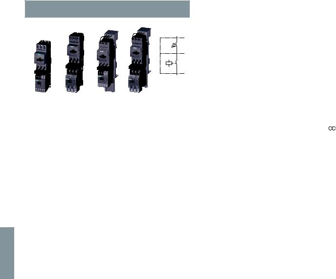
6
© Siemens AG 2011
Combination Starters & Starters for Group Installation
SIRIUS 3RA2 Motor Starters
3RA21 direct-on-line starters 50/60 Hz 110/120 V AC
Direct-on-line starting
3RA21 10 |
3RA21 20 |
3RA21 10 |
3RA21 20 |
Rated control supply voltage 50/60 Hz 110/120 V AC With spring-type connection
•These starters can be assembled in the field without tools by simply snapping the components together. Follow the simple component selection system to form a starter.
•Auxiliary switches1) on the motor starter protector and the contactor can be easily fitted due to the modular system.
•Integrated auxiliary switches:
-Contactor size S00: 1 NO;
-Contactor size S0: 1 NO + 1 NC
Combination Starter, UL508 Type F
All size S00 and S0 devices can be applied as Combination Starters with the addition of either of these line side connectors: 3RV29 28-1H, 3RV29 25-5EB or 3RV29 28-1K.
Size |
UL Data |
|
|
|
|
|
|
FLA setting |
Consisting of the following single devices |
|
Not available |
Weight |
||||||||||||||
|
|
|
|
|
|
|
|
|
range inverse- |
|
|
|
|
|
pre-assembled |
approx. |
||||||||||
|
Single-phase |
Three-phase2) |
|
|
SCCR |
time delayed |
Motor |
+ Contactor |
+ Link module |
+ Busbar |
|
Spring-type |
|
|
|
|||||||||||
|
HP ratings |
HP ratings |
|
|
at |
overload |
starter |
|
|
adapter3) |
|
terminals |
|
|
|
|||||||||||
|
|
|
|
|
|
|
|
480 V |
release |
protector |
|
|
|
|
|
|
|
|
||||||||
|
115 V |
230 V |
200 V |
230 V |
|
460 V |
575 V |
|
|
|
|
|
|
|
|
|
|
|
|
|
Order No. |
|
||||
|
|
|
|
|
|
|
|
|
|
|
|
|
|
|
|
|
|
|||||||||
|
|
|
|
|
|
|
|
kA |
A |
|
|
|
|
|
|
|
|
|
|
kg |
||||||
Selection depends on motor full load amps |
|
|
|
|
|
|
|
|
|
|
|
|
|
|
|
|
|
|
||||||||
|
|
|
|
|
|
|
|
|
|
|
|
|
|
|
|
|
|
3RV20 |
3RT20 |
3RA |
8US12 |
|
|
|
|
|
S00 |
-- |
-- |
-- |
-- |
|
-- |
-- |
65 |
0.14…0.2 |
11-0BA20 |
15-2AK61 |
2911-2AA00 |
51-5DT11 |
|
|
|
|
0.641 |
||||||||
|
-- |
-- |
-- |
-- |
|
-- |
-- |
65 |
0.18…0.25 |
11-0CA20 |
|
|
|
|
|
|
|
0.641 |
||||||||
|
-- |
-- |
-- |
-- |
|
-- |
-- |
65 |
0.22…0.32 |
11-0DA20 |
|
|
|
|
|
|
|
0.641 |
||||||||
|
-- |
-- |
-- |
-- |
|
-- |
-- |
65 |
0.28…0.4 |
11-0EA20 |
|
|
|
|
|
|
|
0.641 |
||||||||
|
-- |
-- |
-- |
-- |
|
-- |
-- |
65 |
0.35…0.5 |
11-0FA20 |
|
|
|
|
|
|
|
0.641 |
||||||||
|
-- |
-- |
-- |
-- |
|
-- |
-- |
65 |
0.45…0.63 |
11-0GA20 |
|
|
|
|
|
|
|
0.641 |
||||||||
|
-- |
-- |
-- |
-- |
|
-- |
-- |
65 |
0.55…0.8 |
11-0HA20 |
|
|
|
|
|
|
|
0.641 |
||||||||
|
-- |
-- |
-- |
-- |
|
-- |
1/2 |
65 |
0.7… |
1 |
11-0JA20 |
|
|
|
|
|
|
|
0.641 |
|||||||
|
-- |
-- |
-- |
-- |
|
1/2 |
1/2 |
65 |
0.9… |
1.25 |
11-0KA20 |
|
|
|
|
|
|
|
0.641 |
|||||||
|
-- |
1/10 |
-- |
-- |
|
3/4 |
3/4 |
65 |
1.1… |
1.6 |
11-1AA20 |
|
|
|
|
|
|
|
0.641 |
|||||||
|
-- |
1/8 |
-- |
-- |
|
3/4 |
1 |
65 |
1.4… |
2 |
11-1BA20 |
|
|
|
|
|
|
|
0.641 |
|||||||
|
-- |
1/6 |
1/2 |
1/2 |
|
1 |
1 1/2 |
65 |
1.8… 2.5 |
11-1CA20 |
|
|
|
|
|
|
|
0.641 |
||||||||
|
1/10 |
1/4 |
1/2 |
3/4 |
|
1 1/2 |
2 |
65 |
2.2… 3.2 |
11-1DA20 |
|
|
|
|
|
|
|
0.641 |
||||||||
|
1/8 |
1/3 |
3/4 |
3/4 |
|
2 |
3 |
65 |
2.8… 4 |
11-1EA20 |
|
|
|
|
|
|
|
0.641 |
||||||||
|
1/6 |
1/2 |
1 |
1 |
|
3 |
3 |
65 |
3.5… 5 |
11-1FA20 |
|
|
|
|
|
|
|
0.641 |
||||||||
|
1/4 |
1/2 |
1 |
1 1/2 |
|
3 |
5 |
65 |
4.5… 6.3 |
11-1GA20 |
|
|
|
|
|
|
|
0.641 |
||||||||
|
1/3 |
1 |
2 |
2 |
|
5 |
5 |
65 |
5.5… 8 |
11-1HA20 |
16-2AK61 |
|
|
|
|
|
|
0.641 |
||||||||
|
1/2 |
1 1/2 |
2 |
3 |
|
5 |
7 1/2 |
65 |
7… 10 |
11-1JA20 |
|
|
|
|
|
|
|
0.641 |
||||||||
|
1/2 |
2 |
3 |
3 |
|
7 1/2 |
10 |
65 |
9… 12 |
11-1KA20 |
17-1AK61 |
|
|
|
|
|
|
0.641 |
||||||||
|
1 |
2 |
3 |
5 |
|
10 |
-- |
65 |
11… |
16 |
11-4AA20 |
18-2AK61 |
|
|
|
|
|
|
0.641 |
|||||||
|
|
|
|
|
|
|
|
|
|
|
|
|
|
|
|
|
|
|
|
|
|
|
|
|
||
S0 |
1/6 |
1/2 |
1 |
1 |
|
3 |
3 |
65 |
3.5… 5 |
11-1FA20 |
24-2AK60 2921-2AA004) |
51-5NT11 |
|
|
|
|
0.925 |
|||||||||
|
1/4 |
1/2 |
1 |
1 1/2 |
|
3 |
5 |
65 |
4.5… 6.3 |
11-1GA20 |
|
+2911-1CA005) |
|
|
|
|
|
0.925 |
||||||||
|
1/3 |
1 |
2 |
2 |
|
5 |
5 |
65 |
5.5… 8 |
11-1HA20 |
|
|
|
|
|
|
|
0.925 |
||||||||
|
1/2 |
1 1/2 |
2 |
3 |
|
5 |
7 1/2 |
65 |
7… |
10 |
11-1JA20 |
|
|
|
|
|
|
|
0.925 |
|||||||
|
1/2 |
2 |
3 |
3 |
|
7 1/2 |
10 |
65 |
9… |
12.5 |
11-1KA20 |
|
|
|
|
|
|
|
0.925 |
|||||||
|
1 |
2 |
3 |
5 |
|
10 |
-- |
65 |
11… |
16 |
21-4AA20 |
26-2AK60 |
|
|
|
|
|
|
0.925 |
|||||||
|
1 1/2 |
3 |
5 |
5 |
|
10 |
-- |
65 |
14… |
20 |
21-4BA20 |
|
|
|
|
|
|
|
0.925 |
|||||||
|
1 1/2 |
3 |
5 |
7 1/2 |
|
15 |
-- |
50 |
17… |
22 |
21-4CA20 |
27-2AK60 |
|
|
|
|
|
|
0.925 |
|||||||
|
2 |
3 |
5 |
7 1/2 |
|
15 |
-- |
50 |
20… |
25 |
21-4DA20 |
|
|
|
|
|
|
|
0.925 |
|||||||
|
2 |
5 |
7 1/2 |
10 |
|
20 |
-- |
50 |
27… |
32 |
21-4EA20 |
|
|
|
|
|
|
|
0.925 |
|||||||
Screw fixing with 1 push-in lug each per motor starter is possible (see "Accessories for Direct-On-Line and Reversing Starters").
1)For auxiliary switches see Accessories page 6/21.
2)Selection depends on motor full load amps. HP ratings for reference only.
3)Use only for mounting starter on 8US Fast Bus busbar systems.
4)Mounting on standard mounting rails with adapter (3RA29 22-1AA00) is possible for feeder-orientated assembly, in which case the contactor must be screwed onto the adapter.
5)For the AC version size S0 with spring loaded terminals, a 3RA29 111CA00 spacer is required for height compensation of the contactor.
6/14 |
SIRIUS Innovations Supplement 2011 |
Illustrations are approximate |
|
|
|
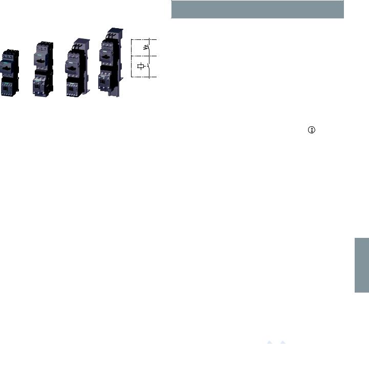
© Siemens AG 2011
Combination Starters & Starters for Group Installation
SIRIUS 3RA2 Motor Starters
3RA21 direct-on-line starters 24 V DC
Direct-on-line starting
3RA21 10 |
3RA21 20 |
3RA21 10 |
3RA21 20 |
Rated control supply voltage 24 V DC
With screw connections
•The motor starter protector and contactor are mechanically and electrically connected by means of the link module.
•Auxiliary switches1) on the motor starter protector and the contactor can be easily fitted due to the modular system.
•Integrated auxiliary switches:
-Contactor size S00: 1 NO;
-Contactor size S0: 1 NO + 1 NC
Combination Starter, UL508 Type F
All size S00 and S0 devices can be applied as Combination Starters with the addition of either of these line side connectors: 3RV29 28-1H, 3RV29 25-5EB or 3RV29 28-1K.
Size |
UL Data |
|
|
|
|
|
|
FLA setting |
Consisting of the following |
|
Assembled starter |
|
|
|
|
Weight |
||||||||||||||||
|
|
|
|
|
|
|
|
|
|
range inverse- |
single devices |
|
|
|
|
|
|
|
|
|
|
|
approx. |
|||||||||
|
Single-phase |
|
Three-phase2) |
|
|
SCCR |
time delayed |
Motor |
+ Contactor |
+ Link |
|
Screw terminals |
|
|
|
|
|
|||||||||||||||
|
HP ratings |
|
HP ratings |
|
|
at |
overload |
starter |
|
module |
|
|
|
|
|
|
|
|
|
|
|
|||||||||||
|
|
|
|
release |
|
|
|
|
|
|
|
|
|
|
|
|
||||||||||||||||
|
|
|
|
|
|
|
|
|
480 V |
protector |
|
+ Busbar |
|
|
|
|
|
|
|
|
|
|
|
|||||||||
|
115 V |
230 V |
|
200 V |
230 V |
|
460 V |
575 V |
|
|
|
|
|
|
|
|
|
|
|
|
adapter3) |
|
Order No. |
|
|
|
|
|
|
|
||
|
|
|
|
|
|
|
|
|
kA |
A |
|
|
|
|
|
|
|
|
|
|
|
|
|
|
|
kg |
||||||
Selection depends on motor full load amps |
|
|
|
|
|
|
|
|
|
|
|
|
|
|
|
|
|
|
|
|
|
|
|
|||||||||
|
|
|
|
|
|
|
|
|
|
|
|
|
|
|
|
|
|
|
3RV20 |
3RT20 |
3RA |
|
|
|
|
|
|
|
|
|
|
|
S00 |
-- |
-- |
|
-- |
-- |
|
-- |
-- |
65 |
0.14…0.2 |
11-0BA10 15-1BB41 |
1921-1DA00 |
|
3RA21 10-0B@15-1BB4 |
|
|
|
|
0.630 |
|||||||||||||
|
-- |
-- |
|
-- |
-- |
|
-- |
-- |
65 |
0.18…0.25 |
11-0CA10 |
|
+ 8US1251- |
|
|
|
|
|
|
0.630 |
||||||||||||
|
|
|
|
|
3RA21 10-0C@15-1BB4 |
|
|
|
|
|||||||||||||||||||||||
|
-- |
-- |
|
-- |
-- |
|
-- |
-- |
65 |
0.22…0.32 |
11-0DA10 |
|
5DS10 |
|
3RA21 10-0D@15-1BB4 |
|
|
|
|
0.630 |
||||||||||||
|
-- |
-- |
|
-- |
-- |
|
-- |
-- |
65 |
0.28…0.4 |
11-0EA10 |
|
|
|
3RA21 10-0E@15-1BB4 |
|
|
|
|
0.630 |
||||||||||||
|
-- |
-- |
|
-- |
-- |
|
-- |
-- |
65 |
0.35…0.5 |
11-0FA10 |
|
|
|
|
|
|
|
|
0.630 |
||||||||||||
|
|
|
|
|
|
3RA21 10-0F@15-1BB4 |
|
|
|
|
||||||||||||||||||||||
|
-- |
-- |
|
-- |
-- |
|
-- |
-- |
65 |
0.45…0.63 |
11-0GA10 |
|
|
|
3RA21 10-0G@15-1BB4 |
|
|
|
|
0.630 |
||||||||||||
|
-- |
-- |
|
-- |
-- |
|
-- |
-- |
65 |
0.55…0.8 |
11-0HA10 |
|
|
|
3RA21 10-0H@15-1BB4 |
|
|
|
|
0.630 |
||||||||||||
|
-- |
-- |
|
-- |
-- |
|
-- |
1/2 |
65 |
0.7… |
1 |
11-0JA10 |
|
|
|
|
|
|
|
|
0.630 |
|||||||||||
|
|
|
|
|
|
3RA21 10-0J@15-1BB4 |
|
|
|
|
||||||||||||||||||||||
|
-- |
-- |
|
-- |
-- |
|
1/2 |
1/2 |
65 |
0.9… |
1.25 |
11-0KA10 |
|
|
|
|
|
|
|
|
0.630 |
|||||||||||
|
|
|
|
|
|
3RA21 10-0K@15-1BB4 |
|
|
|
|
||||||||||||||||||||||
|
-- |
1/10 |
|
-- |
-- |
|
3/4 |
3/4 |
65 |
1.1… |
1.6 |
11-1AA10 |
|
|
|
3RA21 10-1A@15-1BB4 |
|
|
|
|
0.630 |
|||||||||||
|
-- |
1/8 |
|
-- |
-- |
|
3/4 |
1 |
65 |
1.4… 2 |
11-1BA10 |
|
|
|
3RA21 10-1B@15-1BB4 |
|
|
|
|
0.630 |
||||||||||||
|
|
|
|
|
|
|
|
|
|
|
|
|
|
|
|
|
|
|||||||||||||||
|
-- |
1/6 |
|
1/2 |
1/2 |
|
1 |
1 1/2 |
65 |
1.8… |
2.5 |
11-1CA10 |
|
|
|
|
|
|
|
|
0.630 |
|||||||||||
|
|
|
|
|
|
3RA21 10-1C@15-1BB4 |
|
|
|
|
||||||||||||||||||||||
|
1/10 |
1/4 |
|
1/2 |
3/4 |
|
1 1/2 |
2 |
65 |
2.2… 3.2 |
11-1DA10 |
|
|
|
3RA21 10-1D@15-1BB4 |
|
|
|
|
0.630 |
||||||||||||
|
1/8 |
1/3 |
|
3/4 |
3/4 |
|
2 |
3 |
65 |
2.8… 4 |
11-1EA10 |
|
|
|
|
|
|
|
|
0.630 |
||||||||||||
|
|
|
|
|
|
3RA21 10-1E@15-1BB4 |
|
|
|
|
||||||||||||||||||||||
|
1/6 |
1/2 |
|
1 |
1 |
|
3 |
3 |
65 |
3.5… 5 |
11-1FA10 |
|
|
|
3RA21 10-1F@15-1BB4 |
|
|
|
|
0.630 |
||||||||||||
|
1/4 |
1/2 |
|
1 |
1 1/2 |
|
3 |
5 |
65 |
4.5… 6.3 |
11-1GA10 |
|
|
|
|
|
|
|
|
|
||||||||||||
|
|
|
|
|
|
3RA21 10-1G@15-1BB4 |
|
|
|
|
0.630 |
|||||||||||||||||||||
|
1/3 |
1 |
|
2 |
2 |
|
5 |
5 |
65 |
5.5… 8 |
11-1HA10 16-1BB41 |
|
|
|
|
|
|
|
0.630 |
|||||||||||||
|
|
|
|
|
3RA21 10-1H@16-1BB4 |
|
|
|
|
|||||||||||||||||||||||
|
1/2 |
1 1/2 |
|
2 |
3 |
|
5 |
7 1/2 |
65 |
7… 10 |
11-1JA10 |
|
|
|
3RA21 10-1J@16-1BB4 |
|
|
|
|
0.630 |
||||||||||||
|
1/2 |
2 |
|
3 |
3 |
|
7 1/2 |
10 |
65 |
9… 12 |
11-1KA10 17-1BB41 |
|
|
|
|
|
|
|
0.630 |
|||||||||||||
|
|
|
|
|
3RA21 10-1K@17-1BB4 |
|
|
|
|
|||||||||||||||||||||||
|
1 |
2 |
|
3 |
5 |
|
10 |
-- |
65 |
11… 16 |
11-4AA10 18-1BB41 |
|
|
|
|
|
|
|
0.630 |
|||||||||||||
|
|
|
|
|
3RA21 10-4A@18-1BB4 |
|
|
|
|
|||||||||||||||||||||||
S0 |
1/6 |
1/2 |
|
1 |
1 |
|
3 |
3 |
65 |
3.5… 5 |
11-1FA10 24-1BB40 |
2921-1BA00 |
|
3RA21 20-1F@24-0BB4 |
|
|
|
|
0.948 |
|||||||||||||
|
1/4 |
1/2 |
|
1 |
1 1/2 |
|
3 |
5 |
65 |
4.5… 6.3 |
11-1GA10 |
|
+ 8US1251- |
|
|
|
|
|
|
0.948 |
||||||||||||
|
|
|
|
|
3RA21 20-1G@24-0BB4 |
|
|
|
|
|||||||||||||||||||||||
|
1/3 |
1 |
|
2 |
2 |
|
5 |
5 |
65 |
5.5… 8 |
11-1HA10 |
|
5NT10 |
|
|
|
|
|
|
0.948 |
||||||||||||
|
|
|
|
|
3RA21 20-1H@24-0BB4 |
|
|
|
|
|||||||||||||||||||||||
|
1/2 |
1 1/2 |
|
2 |
3 |
|
5 |
7 1/2 |
65 |
7… |
10 |
11-1JA10 |
|
|
|
3RA21 20-1J@24-0BB4 |
|
|
|
|
0.948 |
|||||||||||
|
1/2 |
2 |
|
3 |
3 |
|
7 1/2 |
10 |
65 |
9… |
12.5 |
11-1KA10 |
|
|
|
|
|
|
|
|
0.948 |
|||||||||||
|
|
|
|
|
|
3RA21 20-1K@24-0BB4 |
|
|
|
|
||||||||||||||||||||||
|
1 |
2 |
|
3 |
5 |
|
10 |
-- |
65 |
11… 16 |
21-4AA10 26-1BB40 |
|
|
3RA21 20-4A@26-0BB4 |
|
|
|
|
0.948 |
|||||||||||||
|
1 1/2 |
3 |
|
5 |
5 |
|
10 |
-- |
65 |
14… 20 |
21-4BA10 |
|
|
|
|
|
|
|
|
0.948 |
||||||||||||
|
|
|
|
|
|
3RA21 20-4B@26-0BB4 |
|
|
|
|
||||||||||||||||||||||
|
1 1/2 |
3 |
|
5 |
7 1/2 |
|
15 |
-- |
50 |
17… 22 |
21-4CA10 27-1BB40 |
|
|
3RA21 20-4C@27-0BB4 |
|
|
|
|
0.948 |
|||||||||||||
|
2 |
3 |
|
5 |
7 1/2 |
|
15 |
-- |
50 |
20… 25 |
21-4DA10 |
|
|
|
3RA21 20-4D@27-0BB4 |
|
|
|
|
0.948 |
||||||||||||
|
2 |
5 |
|
7 1/2 |
10 |
|
20 |
-- |
50 |
27… 32 |
21-4EA10 |
|
|
|
|
|
|
|
|
0.948 |
||||||||||||
|
|
|
|
|
|
3RA21 20-4E@27-0BB4 |
|
|
|
|
||||||||||||||||||||||
|
|
|
|
|
|
|
|
|
|
|
|
|
|
|
|
|
|
|
|
|
|
|
|
|
|
|
|
Add. weight |
||||
|
|
|
|
|
|
|
|
|
|
|
|
|
|
|
|
|
|
|
|
|
|
|
|
|
|
|
|
|||||
Order No. supplement for mounting onto standard mounting rail or screw fixing |
|
|
|
|
|
|
A |
|
|
|
|
|
|
|||||||||||||||||||
Screw fixing with 1 push-in lug each per motor starter is possible |
|
|
|
|
|
|
|
|
|
|
|
|
|
|
||||||||||||||||||
(see "Accessories for Direct-On-Line and Reversing Starters"). |
|
|
|
|
|
|
|
|
|
|
|
|
|
|
|
|
||||||||||||||||
Order No. supplement for mounting onto 60 mm busbar |
|
|
|
|
for size S00 |
|
|
1 |
|
D |
|
0.263 |
||||||||||||||||||||
With busbar adapter |
|
|
|
|
|
|
|
|
|
|
|
|
|
|
|
|
|
for size S0 |
|
|
2 |
|
D |
|
0.301 |
|||||||
|
|
|
|
|
|
|
|
|
|
|
|
|
|
|
|
|
|
|
|
|
|
|
|
|
|
|
|
|
|
|
|
|
1)For auxiliary switches see Accessories page 6/21.
2)Selection depends on the concrete motor full load amps. HP ratings for reference only.
3)Use only for mounting starter on 8US Fast Bus busbar systems.
6
Illustrations are approximate |
SIRIUS Innovations Supplement 2011 |
6/15 |
|
|
|

6
© Siemens AG 2011
Combination Starters & Starters for Group Installation
SIRIUS 3RA2 Motor Starters
3RA21 direct-on-line starters 24 V DC
Direct-on-line starting
3RA21 10 |
3RA21 20 |
3RA21 10 |
3RA21 20 |
Rated control supply voltage 24 V DC
With spring-type connection
•These starters can be assembled in the field without tools by simply snapping the components together. Follow the simple component selection system to form a starter.
•Auxiliary switches1) on the motor starter protector and the contactor can be easily fitted due to the modular system.
•Integrated auxiliary switches:
-Contactor size S00: 1 NO;
-Contactor size S0: 1 NO + 1 NC
Combination Starter, UL508 Type F
All size S00 and S0 devices can be applied as Combination Starters with the addition of either of these line side connectors: 3RV29 28-1H, 3RV29 25-5EB or 3RV29 28-1K.
Size |
UL Data |
|
|
|
|
|
|
FLA setting |
Consisting of the following single devices |
|
Not available |
Weight |
||||||||||||||
|
|
|
|
|
|
|
|
|
range inverse- |
|
|
|
|
|
pre-assembled |
approx. |
||||||||||
|
Single-phase |
Three-phase2) |
|
|
SCCR |
time delayed |
Motor |
+ Contactor |
+ Link module |
+ Busbar |
|
Spring-type |
|
|
|
|||||||||||
|
HP ratings |
HP ratings |
|
|
at |
overload |
starter |
|
|
adapter3) |
|
terminals |
|
|
|
|||||||||||
|
|
|
|
|
|
|
|
480 V |
release |
protector |
|
|
|
|
|
|
|
|
||||||||
|
115 V |
230 V |
200 V |
230 V |
|
460 V |
575 V |
|
|
|
|
|
|
|
|
|
|
|
|
|
Order No. |
|
||||
|
|
|
|
|
|
|
|
|
|
|
|
|
|
|
|
|
|
|||||||||
|
|
|
|
|
|
|
|
kA |
A |
|
|
|
|
|
|
|
|
|
|
kg |
||||||
Selection depends on motor full load amps |
|
|
|
|
|
|
|
|
|
|
|
|
|
|
|
|
|
|
||||||||
|
|
|
|
|
|
|
|
|
|
|
|
|
|
|
|
|
|
3RV20 |
3RT20 |
3RA |
8US12 |
|
|
|
|
|
S00 |
-- |
-- |
-- |
-- |
|
-- |
-- |
65 |
0.14…0.2 |
11-0BA20 |
15-2BB41 |
2911-2AA00 |
51-5DT11 |
|
|
|
|
0.641 |
||||||||
|
-- |
-- |
-- |
-- |
|
-- |
-- |
65 |
0.18…0.25 |
11-0CA20 |
|
|
|
|
|
|
|
0.641 |
||||||||
|
-- |
-- |
-- |
-- |
|
-- |
-- |
65 |
0.22…0.32 |
11-0DA20 |
|
|
|
|
|
|
|
0.641 |
||||||||
|
-- |
-- |
-- |
-- |
|
-- |
-- |
65 |
0.28…0.4 |
11-0EA20 |
|
|
|
|
|
|
|
0.641 |
||||||||
|
-- |
-- |
-- |
-- |
|
-- |
-- |
65 |
0.35…0.5 |
11-0FA20 |
|
|
|
|
|
|
|
0.641 |
||||||||
|
-- |
-- |
-- |
-- |
|
-- |
-- |
65 |
0.45…0.63 |
11-0GA20 |
|
|
|
|
|
|
|
0.641 |
||||||||
|
-- |
-- |
-- |
-- |
|
-- |
-- |
65 |
0.55…0.8 |
11-0HA20 |
|
|
|
|
|
|
|
0.641 |
||||||||
|
-- |
-- |
-- |
-- |
|
-- |
1/2 |
65 |
0.7… |
1 |
11-0JA20 |
|
|
|
|
|
|
|
0.641 |
|||||||
|
-- |
-- |
-- |
-- |
|
1/2 |
1/2 |
65 |
0.9… |
1.25 |
11-0KA20 |
|
|
|
|
|
|
|
0.641 |
|||||||
|
-- |
1/10 |
-- |
-- |
|
3/4 |
3/4 |
65 |
1.1… |
1.6 |
11-1AA20 |
|
|
|
|
|
|
|
0.641 |
|||||||
|
-- |
1/8 |
-- |
-- |
|
3/4 |
1 |
65 |
1.4… |
2 |
11-1BA20 |
|
|
|
|
|
|
|
0.641 |
|||||||
|
-- |
1/6 |
1/2 |
1/2 |
|
1 |
1 1/2 |
65 |
1.8… 2.5 |
11-1CA20 |
|
|
|
|
|
|
|
0.641 |
||||||||
|
1/10 |
1/4 |
1/2 |
3/4 |
|
1 1/2 |
2 |
65 |
2.2… 3.2 |
11-1DA20 |
|
|
|
|
|
|
|
0.641 |
||||||||
|
1/8 |
1/3 |
3/4 |
3/4 |
|
2 |
3 |
65 |
2.8… 4 |
11-1EA20 |
|
|
|
|
|
|
|
0.641 |
||||||||
|
1/6 |
1/2 |
1 |
1 |
|
3 |
3 |
65 |
3.5… 5 |
11-1FA20 |
|
|
|
|
|
|
|
0.641 |
||||||||
|
1/4 |
1/2 |
1 |
1 1/2 |
|
3 |
5 |
65 |
4.5… 6.3 |
11-1GA20 |
|
|
|
|
|
|
|
0.641 |
||||||||
|
1/3 |
1 |
2 |
2 |
|
5 |
5 |
65 |
5.5… 8 |
11-1HA20 |
16-2BB41 |
|
|
|
|
|
|
0.641 |
||||||||
|
1/2 |
1 1/2 |
2 |
3 |
|
5 |
7 1/2 |
65 |
7… 10 |
11-1JA20 |
|
|
|
|
|
|
|
0.641 |
||||||||
|
1/2 |
2 |
3 |
3 |
|
7 1/2 |
10 |
65 |
9… 12 |
11-1KA20 |
17-2BB41 |
|
|
|
|
|
|
0.641 |
||||||||
|
1 |
2 |
3 |
5 |
|
10 |
-- |
65 |
11… |
16 |
11-4AA20 |
18-2BB41 |
|
|
|
|
|
|
0.641 |
|||||||
|
|
|
|
|
|
|
|
|
|
|
|
|
|
|
|
|
|
|
|
|
|
|
|
|
|
|
S0 |
1/6 |
1/2 |
1 |
1 |
|
3 |
3 |
65 |
3.5… 5 |
11-1FA20 |
24-2BB40 |
2921-2AA00 |
51-5NT11 |
|
|
|
|
0.925 |
||||||||
|
1/4 |
1/2 |
1 |
1 1/2 |
|
3 |
5 |
65 |
4.5… 6.3 |
11-1GA20 |
|
|
|
|
|
|
|
0.925 |
||||||||
|
1/3 |
1 |
2 |
2 |
|
5 |
5 |
65 |
5.5… 8 |
11-1HA20 |
|
|
|
|
|
|
|
0.925 |
||||||||
|
1/2 |
1 1/2 |
2 |
3 |
|
5 |
7 1/2 |
65 |
7… |
10 |
11-1JA20 |
|
|
|
|
|
|
|
0.925 |
|||||||
|
1/2 |
2 |
3 |
3 |
|
7 1/2 |
10 |
65 |
9… |
12.5 |
11-1KA20 |
|
|
|
|
|
|
|
0.925 |
|||||||
|
1 |
2 |
3 |
5 |
|
10 |
-- |
65 |
11… |
16 |
21-4AA20 |
26-2BB40 |
|
|
|
|
|
|
0.925 |
|||||||
|
1 1/2 |
3 |
5 |
5 |
|
10 |
-- |
65 |
14… |
20 |
21-4BA20 |
|
|
|
|
|
|
|
0.925 |
|||||||
|
1 1/2 |
3 |
5 |
7 1/2 |
|
15 |
-- |
50 |
17… |
22 |
21-4CA20 |
27-2BB40 |
|
|
|
|
|
|
0.925 |
|||||||
|
2 |
3 |
5 |
7 1/2 |
|
15 |
-- |
50 |
20… |
25 |
21-4DA20 |
|
|
|
|
|
|
|
0.925 |
|||||||
|
2 |
5 |
7 1/2 |
10 |
|
20 |
-- |
50 |
27… |
32 |
21-4EA20 |
|
|
|
|
|
|
|
0.925 |
|||||||
Screw fixing with 1 push-in lug each per motor starter is possible.
1)For auxiliary switches see Accessories page 6/21.
2)Selection depends on the motor full load amps. HP ratings for reference only.
3)Used only for mounting starter on 8US Fast Bus busbar systems.
4)Mounting on standard mounting rails or with screws (3RA29 22-1AA00) is possible for feeder-orientated assembly, in which case the contactor must be screwed onto the adapter.
6/16 |
SIRIUS Innovations Supplement 2011 |
Illustrations are approximate |
|
|
|
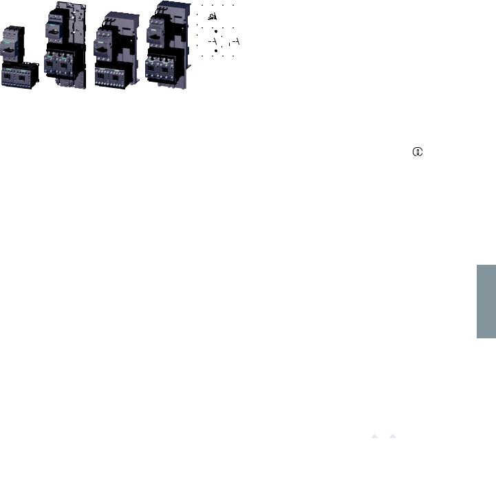
© Siemens AG 2011
Combination Starters & Starters for Group Installation
|
|
|
|
|
|
|
|
|
|
|
|
|
|
|
|
SIRIUS 3RA2 Motor Starters |
|
|
|
|
|
|
|
|
|
|
|
|
|
|
|
|
|
|
3RA22 reversing starters |
|
|
|
|
|
|
|
|
|
|
|
|
|
|
|
|
|
|
50/60 Hz 110/120 V AC |
|
|
|
|
|
|
|
|
|
|
|
|
|
|
|
|
|
|
|
|
|
|
■ Selection and ordering data |
|
|
|
||||||||||||||
|
Reversing duty |
Rated control supply voltage 50/60 Hz 110/120 V AC |
|
|||||||||||||||
|
With screw connections |
|
||||||||||||||||
|
|
|
|
|
|
|
|
|
|
|
|
|
|
|
|
|
||
|
|
|
|
|
|
|
|
|
|
|
|
|
|
|
|
• The motor starter protector and contactor are mechan- |
|
|
|
|
|
|
|
|
|
|
|
|
|
|
|
|
|
|
|
||
|
|
|
|
|
|
|
|
|
|
|
|
|
|
|
|
|
||
|
|
|
|
|
|
|
|
|
|
|
|
|
|
|
|
ically and electrically connected by means of the link |
|
|
|
|
|
|
|
|
|
|
|
|
|
|
|
|
|
|
|
||
|
|
|
|
|
|
|
|
|
|
|
|
|
|
|
|
module. |
|
|
|
|
|
|
|
|
|
|
|
|
|
|
|
|
|
|
• Auxiliary switches1) on the motor starter protector and |
|
|
|
|
|
|
|
|
|
|
|
|
|
|
|
|
|
|
the contactor can be easily fitted due to the modular |
|
|
|
|
|
|
|
|
|
|
|
|
|
|
|
|
|
|
system. |
|
|
|
|
|
|
|
|
|
|
|
|
|
|
|
|
|
|
|
||
|
|
|
|
|
|
|
|
|
|
|
|
|
|
|
|
• With the contactor S0, an integrated NO contact is |
|
|
|
|
|
|
|
|
|
|
|
|
|
|
|
|
|
|
available for free use. |
|
|
|
|
|
|
|
|
|
|
|
|
|
|
|
|
|
|
|
|
|
Combination Starter, UL508 Type F |
|
|
|
|
|
|||||
3RA22 10 |
3RA22 20 |
3RA22 10 |
3RA22 20 |
|
|
|
All size S00 and S0 devices can be applied as Combina- |
||||||||||||||||||||||
|
|
|
|
|
|
|
|
|
|
|
|
|
|
|
|
|
|
|
tion Starters with the addition of either of these line side |
||||||||||
|
|
|
|
|
|
|
|
|
|
|
|
|
|
|
|
|
|
|
connectors: 3RV29 28-1H, 3RV29 25-5EB or |
|
|||||||||
|
|
|
|
|
|
|
|
|
|
|
|
|
|
|
|
|
|
|
3RV29 28-1K. |
|
|
|
|
|
|
|
|
|
|
|
|
|
|
|
|
|
|
|
|
|
|
|
|
|
|
|
|
|
|
|
|
|
|
|
|||||
Size |
UL Data |
|
|
|
|
|
|
FLA setting |
Consisting of the following single devices |
|
Assembled starter |
Weight |
|||||||||||||||||
|
|
|
|
|
|
|
|
|
range inverse- |
|
|
|
|
|
|
|
|
|
|
|
approx. |
||||||||
|
|
|
|
2) |
|
|
|
time delayed |
|
|
|
|
|
|
|
|
|
|
|
|
|||||||||
|
Single-phase |
Three-phase |
|
|
SCCR |
overload |
Motor starter |
+ 2 contac- |
+ Link module |
|
Screw terminals |
|
|
|
|||||||||||||||
|
HP ratings |
HP ratings |
|
|
at |
protector |
tors |
+ Assembly kit |
|
|
|
|
|
|
|
|
|
||||||||||||
|
|
|
release |
|
|
|
|
|
|
|
|
|
|||||||||||||||||
|
|
|
|
|
|
|
|
480 V |
|
|
RH/RS3) |
|
|
|
|
|
|
|
|
|
|||||||||
|
115 V |
230 V |
200 V |
230 V |
|
460 V |
575 V |
|
|
|
|
|
|
|
|
|
|
|
|
Order No. |
|
|
|
|
|
||||
|
|
|
|
|
|
|
|
kA |
A |
|
|
|
|
|
|
|
|
|
|
|
|
|
kg |
||||||
Selection depends on motor full load amps |
|
|
|
|
|
|
|
|
|
|
|
|
|
|
|
|
|
|
|
|
|
||||||||
|
|
|
|
|
|
|
|
|
|
|
|
|
|
|
|
|
|
3RV20 |
3RT20 |
3RA |
|
|
|
|
|
|
|
|
|
S00 |
-- |
-- |
-- |
-- |
|
-- |
-- |
65 |
0.14…0.2 |
11-0BA10 |
15-1AK62 |
1921-1DA00 |
|
3RA22 10-0B@15-2AK6 |
0.824 |
||||||||||||||
|
-- |
-- |
-- |
-- |
|
-- |
-- |
65 |
0.18…0.25 |
11-0CA10 |
|
+ 2913-2AA14) |
|
3RA22 10-0C@15-2AK6 |
0.824 |
||||||||||||||
|
-- |
-- |
-- |
-- |
|
-- |
-- |
65 |
0.22…0.32 |
11-0DA10 |
|
+ 2913-1DB1 (RS) |
|
|
|
|
0.824 |
||||||||||||
|
|
|
|
3RA22 10-0D@15-2AK6 |
|||||||||||||||||||||||||
|
-- |
-- |
-- |
-- |
|
-- |
-- |
65 |
0.28…0.4 |
11-0EA10 |
|
|
|
|
|
|
0.824 |
||||||||||||
|
|
|
|
|
3RA22 10-0E@15-2AK6 |
||||||||||||||||||||||||
|
-- |
-- |
-- |
-- |
|
-- |
-- |
65 |
0.35…0.5 |
11-0FA10 |
|
|
|
3RA22 10-0F@15-2AK6 |
0.824 |
||||||||||||||
|
-- |
-- |
-- |
-- |
|
-- |
-- |
65 |
0.45…0.63 |
11-0GA10 |
|
|
|
|
|
|
0.824 |
||||||||||||
|
|
|
|
|
3RA22 10-0G@15-2AK6 |
||||||||||||||||||||||||
|
-- |
-- |
-- |
-- |
|
-- |
-- |
65 |
0.55…0.8 |
11-0HA10 |
|
|
|
|
|
|
0.824 |
||||||||||||
|
|
|
|
|
3RA22 10-0H@15-2AK6 |
||||||||||||||||||||||||
|
-- |
-- |
-- |
-- |
|
-- |
1/2 |
65 |
0.7… |
1 |
11-0JA10 |
|
|
|
3RA22 10-0J@15-2AK6 |
0.824 |
|||||||||||||
|
-- |
-- |
-- |
-- |
|
1/2 |
1/2 |
65 |
0.9… |
1.25 |
11-0KA10 |
|
|
|
3RA22 10-0K@15-2AK6 |
0.824 |
|||||||||||||
|
-- |
1/10 |
-- |
-- |
|
3/4 |
3/4 |
65 |
1.1… |
1.6 |
11-1AA10 |
|
|
|
|
|
|
0.824 |
|||||||||||
|
|
|
|
|
3RA22 10-1A@15-2AK6 |
||||||||||||||||||||||||
|
-- |
1/8 |
-- |
-- |
|
3/4 |
1 |
65 |
1.4… |
2 |
11-1BA10 |
|
|
|
3RA22 10-1B@15-2AK6 |
0.824 |
|||||||||||||
|
-- |
1/6 |
1/2 |
1/2 |
|
1 |
1 1/2 |
65 |
1.8… 2.5 |
11-1CA10 |
|
|
|
3RA22 10-1C@15-2AK6 |
0.824 |
||||||||||||||
|
1/10 |
1/4 |
1/2 |
3/4 |
|
1 1/2 |
2 |
65 |
2.2… 3.2 |
11-1DA10 |
|
|
|
|
|
|
0.824 |
||||||||||||
|
|
|
|
|
3RA22 10-1D@15-2AK6 |
||||||||||||||||||||||||
|
1/8 |
1/3 |
3/4 |
3/4 |
|
2 |
3 |
65 |
2.8… 4 |
11-1EA10 |
|
|
|
|
|
|
0.824 |
||||||||||||
|
|
|
|
|
3RA22 10-1E@15-2AK6 |
||||||||||||||||||||||||
|
1/6 |
1/2 |
1 |
1 |
|
3 |
3 |
65 |
3.5… 5 |
11-1FA10 |
|
|
|
|
|
|
0.824 |
||||||||||||
|
|
|
|
|
3RA22 10-1F@15-2AK6 |
||||||||||||||||||||||||
|
1/4 |
1/2 |
1 |
1 1/2 |
|
3 |
5 |
65 |
4.5… 6.3 |
11-1GA10 |
|
|
|
3RA22 10-1G@15-2AK6 |
0.824 |
||||||||||||||
|
1/3 |
1 |
2 |
2 |
|
5 |
5 |
65 |
5.5… 8 |
11-1HA10 |
16-1AK62 |
|
|
|
|
|
0.824 |
||||||||||||
|
|
|
|
3RA22 10-1H@16-2AK6 |
|||||||||||||||||||||||||
|
1/2 |
1 1/2 |
2 |
3 |
|
5 |
7 1/2 |
65 |
7… 10 |
11-1JA10 |
|
|
|
|
|
|
0.824 |
||||||||||||
|
|
|
|
|
3RA22 10-1J@16-2AK6 |
||||||||||||||||||||||||
|
1/2 |
2 |
3 |
3 |
|
7 1/2 |
10 |
65 |
9… 12 |
11-1KA10 |
17-1AK62 |
|
|
3RA22 10-1K@17-2AK6 |
0.824 |
||||||||||||||
|
1 |
2 |
3 |
5 |
|
10 |
-- |
65 |
11… 16 |
11-4AA10 |
18-1AK62 |
|
|
3RA22 10-4A@18-2AK6 |
0.824 |
||||||||||||||
S0 |
1/6 |
1/2 |
1 |
1 |
|
3 |
3 |
65 |
3.5… 5 |
11-1FA10 |
24-1AK60 |
2921-1AA00 |
|
3RA22 20-1F@24-0AK6 |
1.434 |
||||||||||||||
|
1/4 |
1/2 |
1 |
1 1/2 |
|
3 |
5 |
65 |
4.5… 6.3 |
11-1GA10 |
|
+ 2923-1BB1 (RH) |
|
3RA22 20-1G@24-0AK6 |
1.434 |
||||||||||||||
|
1/3 |
1 |
2 |
2 |
|
5 |
5 |
65 |
5.5… 8 |
11-1HA10 |
|
+ 2923-1DB1 (RS) |
|
3RA22 20-1H@24-0AK6 |
1.434 |
||||||||||||||
|
1/2 |
1 1/2 |
2 |
3 |
|
5 |
7 1/2 |
65 |
7… |
10 |
11-1JA10 |
|
|
|
|
|
|
1.434 |
|||||||||||
|
|
|
|
|
3RA22 20-1J@24-0AK6 |
||||||||||||||||||||||||
|
1/2 |
2 |
3 |
3 |
|
7 1/2 |
10 |
65 |
9… |
12.5 |
11-1KA10 |
|
|
|
|
|
|
1.434 |
|||||||||||
|
|
|
|
|
3RA22 20-1K@24-0AK6 |
||||||||||||||||||||||||
|
1 |
2 |
3 |
5 |
|
10 |
-- |
65 |
11… 16 |
21-4AA10 |
26-1AK60 |
|
|
3RA22 20-4A@26-0AK6 |
1.434 |
||||||||||||||
|
1 1/2 |
3 |
5 |
5 |
|
10 |
-- |
65 |
14… 20 |
21-4BA10 |
|
|
|
|
|
|
1.434 |
||||||||||||
|
|
|
|
|
3RA22 20-4B@26-0AK6 |
||||||||||||||||||||||||
|
1 1/2 |
3 |
5 |
7 1/2 |
|
15 |
-- |
50 |
17… 22 |
21-4CA10 |
27-1AK60 |
|
|
|
|
|
1.434 |
||||||||||||
|
|
|
|
3RA22 20-4C@27-0AK6 |
|||||||||||||||||||||||||
|
2 |
3 |
5 |
7 1/2 |
|
15 |
-- |
50 |
20… 25 |
21-4DA10 |
|
|
|
3RA22 20-4D@27-0AK6 |
1.434 |
||||||||||||||
|
2 |
5 |
7 1/2 |
10 |
|
20 |
-- |
50 |
27… 32 |
21-4EA10 |
|
|
|
3RA22 20-4E@27-0AK6 |
1.434 |
||||||||||||||
|
|
|
|
|
|
|
|
|
|
|
|
|
|
|
|
|
|
|
|
|
|
|
|
|
|
|
Add. weight |
||
|
|
|
|
|
|
|
|
|
|
|
|
|
|
|
|
|
|
|
|
|
|
|
|
|
|
||||
Order No. supplement for mounting onto standard mounting rail or screw fixing |
|
|
|
|
|
|
|
|
|
|
|
||||||||||||||||||
• Without standard mounting rail adapter for size S004) |
|
|
|
|
|
|
|
|
|
|
|
|
|
|
1 |
|
A |
|
|
|
|
||||||||
• With 2 standard mounting rail adapters for size S0 |
|
|
|
|
|
|
|
|
|
|
|
|
|
|
2 |
|
B |
|
|
|
|
||||||||
Screw fixing with 2 push-in lugs each per motor starter is possible |
|
|
|
|
|
|
|
|
|
|
|
|
|||||||||||||||||
Order No. supplement for mounting onto 60 mm busbar |
|
|
|
|
for size S00 |
|
|
1 |
|
D |
|
|
|
0.486 |
|||||||||||||||
With 8US Fast Bus busbar adapter |
|
|
|
|
|
|
|
|
|
|
|
|
|
for size S0 |
|
|
2 |
|
D |
|
|
|
0.293 |
||||||
|
|
|
|
|
|
|
|
|
|
|
|
|
|
|
|
|
|
|
|
|
|
|
|
|
|
|
|
|
|
1)For push-in lugs and auxiliary switches see Accessories.
2)Selection depends on the motor full load amps. HP ratings for reference only.
3)According to ordering option:
RH = assembly kit for reversing duty with standard rail mounting adapter in size S0.
RS = assembly kit for reversing duty with 8US Fast Bus busbar mounting.
4)With standard rail mounting or screw fixing, the 3RA29 13-2AA1 wiring kit is required for size S00.
6
Illustrations are approximate |
SIRIUS Innovations Supplement 2011 |
6/17 |
|
|
|
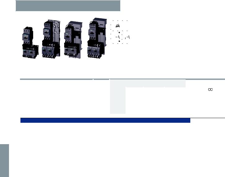
6
© Siemens AG 2011
Combination Starters & Starters for Group Installation
SIRIUS 3RA2 Motor Starters
3RA22 reversing starters 50/60 Hz 110/120 V AC
|
|
|
|
Reversing duty |
Rated control supply voltage 50/60 Hz 110/120 V AC |
||||||||||||||||||
|
|
|
|
With spring-type connection |
|||||||||||||||||||
|
|
|
|
|
|
|
|
|
|
|
|
|
|
|
|
|
|
|
|
|
|
|
|
|
|
|
|
|
|
|
|
|
|
|
|
|
|
|
|
|
|
|
|
|
|
|
• These starters can be assembled in the field without |
|
|
|
|
|
|
|
|
|
|
|
|
|
|
|
|
|
|
|
|
|
|
|
|
|
|
|
|
|
|
|
|
|
|
|
|
|
|
|
|
|
|
|
|
|
|
|
|
|
|
|
|
|
|
|
|
|
|
|
|
|
|
|
|
|
|
|
|
|
|
|
tools by simply snapping the components together. |
|
|
|
|
|
|
|
|
|
|
|
|
|
|
|
|
|
|
|
|
|
|
|
|
|
|
|
|
|
|
|
|
|
|
|
|
|
|
|
|
|
|
|
|
|
|
|
Follow the simple component selection system to form |
|
|
|
|
|
|
|
|
|
|
|
|
|
|
|
|
|
|
|
|
|
|
|
a starter. |
|
|
|
|
|
|
|
|
|
|
|
|
|
|
|
|
|
|
|
|
|
|
|
• Auxiliary switches1) on the motor starter protector and |
|
|
|
|
|
|
|
|
|
|
|
|
|
|
|
|
|
|
|
|
|
|
|
the contactor can be easily fitted due to the modular |
|
|
|
|
|
|
|
|
|
|
|
|
|
|
|
|
|
|
|
|
|
|
|
|
|
|
|
|
|
|
|
|
|
|
|
|
|
|
|
|
|
|
|
|
|
|
|
system. |
|
|
|
|
|
|
|
|
|
|
|
|
|
|
|
|
|
|
|
|
|
|
|
• With the contactor S0, an integrated NO contact is |
|
|
|
|
|
|
|
|
|
|
|
|
|
|
|
|
|
|
|
|
|
|
|
available for free use. |
3RA22 10 |
3RA22 20 |
3RA22 10 |
3RA22 20 |
|
|
|
|
|
|
|
|
|
|
|
|
|
|
|
|
|
|
|
Combination Starter, UL508 Type F |
All size S00 and S0 devices can be applied as Combination Starters with the addition of either of these line side connectors: 3RV29 28-1H, 3RV29 25-5EB or
3RV29 28-1K.
Size |
UL Data |
|
|
|
|
|
FLA set- |
|||||||||
|
|
|
|
|
|
|
|
ting range |
||||||||
|
Single-phase |
2) |
|
SCCR |
inverse- |
|||||||||||
|
|
|||||||||||||||
|
Three-phase |
|
time |
|||||||||||||
|
HP ratings |
HP ratings |
|
at |
delayed |
|||||||||||
|
|
|
|
|
|
|
480 V |
|||||||||
|
|
|
|
|
|
|
|
overload |
||||||||
|
|
|
|
|
|
|
|
release |
||||||||
|
|
|
|
|
|
|
|
|
|
|
|
|
|
|
|
|
|
115 V |
230 V |
200 V |
230 V |
460 V |
575 V |
|
|
|
|
|
|
|
|
|
|
|
|
|
|
|
|
|
kA |
A |
||||||||
Consisting of the following single devices |
Not available |
Weight |
||||||
|
|
|
|
|
pre-assembled |
approx. |
||
Motor |
+ 2 contac- |
Standard rail |
8US Busbar |
|
Spring-type |
|
|
|
starter |
tors |
or screw |
mounting |
|
terminals |
|
|
|
protector |
|
mounting |
system |
|
|
|
|
|
|
|
+ Link module |
+ Link module |
|
|
|
|
|
|
|
+ Assembly kit |
+ Assembly kit |
|
|
|
|
|
|
|
(RH)3) |
(RS)3) |
|
|
|
|
|
|
|
|
|
|
Order No. |
|
||
|
|
|
|
|
|
|
|
kg |
|
|
|
|
|
|
|
|
|
|
|
|
|
|
|
|
|
|
Selection depends on motor full load amps
|
|
|
|
|
|
|
|
|
|
3RV20 |
3RT20 |
3RA |
3RA |
|
S00 |
-- |
-- |
-- |
-- |
-- |
-- |
65 |
0.14…0.2 |
11-0BA20 |
15-2AK62 |
2911-2AA00 |
2911-2AA00 |
0.641 |
|
|
-- |
-- |
-- |
-- |
-- |
-- |
65 |
0.18…0.25 |
11-0CA20 |
|
+ 2913-2AA24) |
+ 2913-1DB25) |
0.641 |
|
|
-- |
-- |
-- |
-- |
-- |
-- |
65 |
0.22…0.32 |
11-0DA20 |
|
|
|
0.641 |
|
|
-- |
-- |
-- |
-- |
-- |
-- |
65 |
0.28…0.4 |
11-0EA20 |
|
|
|
0.641 |
|
|
-- |
-- |
-- |
-- |
-- |
-- |
65 |
0.35…0.5 |
11-0FA20 |
|
|
|
0.641 |
|
|
-- |
-- |
-- |
-- |
-- |
-- |
65 |
0.45…0.63 |
11-0GA20 |
|
|
|
0.641 |
|
|
-- |
-- |
-- |
-- |
-- |
-- |
65 |
0.55…0.8 |
11-0HA20 |
|
|
|
0.641 |
|
|
-- |
-- |
-- |
-- |
-- |
1/2 |
65 |
0.7… |
1 |
11-0JA20 |
|
|
|
0.641 |
|
-- |
-- |
-- |
-- |
1/2 |
1/2 |
65 |
0.9… |
1.25 |
11-0KA20 |
|
|
|
0.641 |
|
-- |
1/10 |
-- |
-- |
3/4 |
3/4 |
65 |
1.1… |
1.6 |
11-1AA20 |
|
|
|
0.641 |
|
-- |
1/8 |
-- |
-- |
3/4 |
1 |
65 |
1.4… |
2 |
11-1BA20 |
|
|
|
0.641 |
|
-- |
1/6 |
1/2 |
1/2 |
1 |
1 1/2 |
65 |
1.8… 2.5 |
11-1CA20 |
|
|
|
0.641 |
|
|
1/10 |
1/4 |
1/2 |
3/4 |
1 1/2 |
2 |
65 |
2.2… 3.2 |
11-1DA20 |
|
|
|
0.641 |
|
|
1/8 |
1/3 |
3/4 |
3/4 |
2 |
3 |
65 |
2.8… 4 |
11-1EA20 |
|
|
|
0.641 |
|
|
1/6 |
1/2 |
1 |
1 |
3 |
3 |
65 |
3.5… 5 |
11-1FA20 |
|
|
|
0.641 |
|
|
1/4 |
1/2 |
1 |
1 1/2 |
3 |
5 |
65 |
4.5… 6.3 |
11-1GA20 |
|
|
|
0.641 |
|
|
1/3 |
1 |
2 |
2 |
5 |
5 |
65 |
5.5… 8 |
11-1HA20 |
16-2AK62 |
|
|
0.641 |
|
|
1/2 |
1 1/2 |
2 |
3 |
5 |
7 1/2 |
65 |
7… 10 |
11-1JA20 |
|
|
|
0.641 |
|
|
1/2 |
2 |
3 |
3 |
7 1/2 |
10 |
65 |
9… 12 |
11-1KA20 |
17-1AK62 |
|
|
0.641 |
|
|
1 |
2 |
3 |
5 |
10 |
-- |
65 |
11… |
16 |
11-4AA20 |
18-2AK62 |
|
|
0.641 |
S0 |
1/6 |
1/2 |
1 |
1 |
3 |
3 |
65 |
3.5… 5 |
11-1FA20 |
24-2AK60 |
2921-2AA00 |
2921-2AA00 |
0.925 |
|
|
1/4 |
1/2 |
1 |
1 1/2 |
3 |
5 |
65 |
4.5… 6.3 |
11-1GA20 |
|
+ 2923-1BB25) |
+ 2923-1DB25) |
0.925 |
|
|
1/3 |
1 |
2 |
2 |
5 |
5 |
65 |
5.5… 8 |
11-1HA20 |
|
|
|
0.925 |
|
|
1/2 |
1 1/2 |
2 |
3 |
5 |
7 1/2 |
65 |
7… |
10 |
11-1JA20 |
|
|
|
0.925 |
|
1/2 |
2 |
3 |
3 |
7 1/2 |
10 |
65 |
9… |
12.5 |
11-1KA20 |
|
|
|
0.925 |
|
1 |
2 |
3 |
5 |
10 |
-- |
65 |
11… |
16 |
21-4AA20 |
26-2AK60 |
|
|
0.925 |
|
1 1/2 |
3 |
5 |
5 |
10 |
-- |
65 |
14… |
20 |
21-4BA20 |
|
|
|
0.925 |
|
1 1/2 |
3 |
5 |
7 1/2 |
15 |
-- |
50 |
17… |
22 |
21-4CA20 |
27-2AK60 |
|
|
0.925 |
|
2 |
3 |
5 |
7 1/2 |
15 |
-- |
50 |
20… |
25 |
21-4DA20 |
|
|
|
0.925 |
|
2 |
5 |
7 1/2 |
10 |
20 |
-- |
50 |
27… |
32 |
21-4EA20 |
|
|
|
0.925 |
Screw fixing with 2 push-in lugs each per motor starter is possible with RH configured starters. (see "Accessories for Direct-On-Line and Reversing Starters").
1)For push-in lugs and auxiliary switches see Accessories.
2)Selection depends on the motor full load amps. HP ratings for reference only.
3)Code for abbreviations:
RH = assembly kit for reversing duty and standard rail mounting adapter in size S0.
RS = assembly kit for reversing duty and busbar mounting.
4)With standard rail mounting or screw fixing, the 3RA29 13-2AA2 wiring kit and link module are required for size S00.
5)The RH/RS assembly kits also include 3RA29 11-1CA00 spacer for height compensation on AC contactors size S0 with spring-type terminals.
6/18 |
SIRIUS Innovations Supplement 2011 |
Illustrations are approximate |
|
|
|
 Loading...