


 Loading...
MICROMASTER 440
Parameter List |
Issue 08/02 |
User Documentation
6SE6400-5BB00-0BP0
Available Documentation for the MICROMASTER 440
Getting Started Guide
Is for quick commissioning with SDP and BOP.
Operating Instructions
Gives information about features of the MICROMASTER440, Installation, Commissioning, Control modes, System Parameter structure, Troubleshooting, Specifications and available options of the MICROMASTER440.
Parameter List
The Parameterlist containes the description of all Parameters structured in functional order and a detailed description. The Parameter list also includes a series of function plans.
Catalogues
In the catalogue you will find all needs to select a certain inverter, as well as filters chokes, operator panels or communications options.

MICROMASTER 440
Parameter List
User Documentation
Parameter List |
1 |
|
|
Function Diagrams |
2 |
|
|
Alarms and |
3 |
Warnings |
|
Valid for |
Issue 08/02 |
Converter Type |
|
MICROMASTER 440 |
Software Version V2.0 |
Issue 08/02

1 Parameters |
Issue 08/02 |
Warning
!Please refer to all Definitiones and Warnings contained in the Operating Instructions. You will find the Operating Instructions on the Docu CD delivered with your inverter. If the CD is lost, it can be ordered via your local Siemens department under the Order No. 6SE6400-5AD00-1AP0.
Further information can be obtained from Internet website: http://www.siemens.de/micromaster
Approved Siemens Quality for Software and Training is to DIN ISO 9001, Reg. No. 2160-01
The reproduction, transmission or use of this document, or its contents is not permitted unless authorized in writing. Offenders will be liable for damages. All rights including rights created by patent grant or registration of a utility model or design are reserved.
© Siemens AG 2001, 2002. All Rights Reserved.
MICROMASTER® is a registered trademark of Siemens
Other functions not described in this document may be available. However, this fact shall not constitute an obligation to supply such functions with a new control, or when servicing.
We have checked that the contents of this document correspond to the hardware and software described. There may be discrepancies nevertheless, and no guarantee can be given that they are completely identical. The information contained in this document is reviewed regularly and any necessary changes will be included in the next edition. We welcome suggestions for improvement.
Siemens handbooks are printed on chlorine-free paper that has been produced from managed sustainable forests. No solvents have been used in the printing or binding process.
Document subject to change without prior notice.
Printed in the Federal of Germany |
Siemens-Aktiengesellschaft. |
4 |
MICROMASTER 440 Parameter List |
6SE6400-5BB00-0BP0 |
Issue 08/02 |
1 Parameters |
Parameters MICROMASTER 440
This Parameter List must only be used together with the Operating Instructions or the Reference Manual of the MICROMASTER 440. Please pay special attention to the Warnings, Cautions, Notices and Notes contained in these manuals.
Table of Contents |
|
|
1 |
Parameters .......................................................................................... |
7 |
1.1 |
Introduction to MICROMASTER 440 System Parameters................... |
7 |
1.2 |
Quick commissioning (P0010=1).......................................................... |
9 |
1.3 |
Command and Drive Datasets - Overview ......................................... |
11 |
1.4 |
Binector Input-Parameter.................................................................... |
15 |
1.5 |
Connector Input-Parameter ................................................................ |
16 |
1.6 |
Binektor Output-Parameter................................................................. |
16 |
1.7 |
Connector Output Parameter ............................................................. |
17 |
1.8 |
Connector/Binector Output-Parameter............................................... |
18 |
1.9 |
Parameter Description........................................................................ |
19 |
2 |
Function Diagrams ......................................................................... |
227 |
3 |
Faults and Alarms........................................................................... |
269 |
3.1 |
Fault messages ................................................................................ |
269 |
3.2 |
Alarm Messages ............................................................................... |
274 |
MICROMASTER 440 |
Parameter List |
6SE6400-5BB00-0BP0 |
5 |
1 Parameters |
Issue 08/02 |
6 |
MICROMASTER 440 Parameter List |
6SE6400-5BB00-0BP0 |

Issue 08/02 |
1 Parameters |
1 Parameters
1.1Introduction to MICROMASTER 440 System Parameters
The layout of the parameter description is as follows.
1 Par number |
2 Parameter name |
5 Datatype |
7 Unit: |
9 Min: |
[index] |
3 CStat: |
10 Def: |
||
|
4 P-Group: |
6 active: |
8 Quick Comm: |
11 Max: |
|
13 |
Description: |
|
|
12 Level:
2
1.Parameter number
Indicates the relevant parameter number. The numbers used are 4-digit numbers in the range 0000 to 9999. Numbers prefixed with an “r” indicate that the parameter is a “read-only” parameter, which displays a particular value but cannot be changed directly by specifying a different value via this parameter number (in such cases, dashes “-“ are entered at the points “Unit”, “Min”, “Def” and “Max” in the header of the parameter description.
All other parameters are prefixed with a “P”. The values of these parameters can be changed directly in the range indicated by the “Min” and “Max” settings in the header.
[index] indicates that the parameter is an indexed parameter and specifies the number of indices available.
2.Parameter name
Indicates the name of the relevant parameter. Certain parameter names include the following abbreviated prefixes: BI, BO, CI, and CO followed by a colon. These abbreviations have the following meanings:
BI |
= |
|
|
Binector input, i.e. parameter selects the source of a |
P9999.C |
|
|||
|
|
|
(0) |
binary signal |
|
|
|
|
|
BO |
= |
r9999 |
|
Binector output, i.e. parameter connects as a binary |
|
|
|
|
signal |
CI =
CO =
P9999.D
(999:9)
r9999 [99]
Connector input, i.e. parameter selects the source of an analog signal
Connector output, i.e. parameter connects as an analog signal
CO/BO = r9999 |
Connector/Binector output, i.e. parameter connects as |
r9999 |
an analog signal and/or as a binary signal |
To make use of BiCo you will need access to the full parameter list. At this level many new parameter settings are possible, including BiCo functionality. BiCo functionality is a different, more flexible way of setting and combining input and output functions. It can be used in most cases in conjunction with the simple, level 2 settings.
The BiCo system allows complex functions to be programmed. Boolean and mathematical relationships can be set up between inputs (digital, analog, serial etc.) and outputs (inverter current, frequency, analog output, relays, etc.).
MICROMASTER 440 |
Parameter List |
6SE6400-5BB00-0BP0 |
7 |

1 Parameters |
Issue 08/02 |
3.CStat
Commissioning status of the parameter. Three states are possible:
Commissioning |
C |
Run |
U |
Ready to run |
T |
This indicates when the parameter can be changed. One, two or all three states may be specified. If all three states are specified, this means that it is possible to change this parameter setting in all three inverter states
4.P-Group
Indicates the functional group of the particular.
Note
Parameter P0004 (parameter filter) acts as a filter and focuses access to parameters according to the functional group selected.
5.Datatype
The data types available are shown in the table below.
Notation |
Meaning |
U16 |
16-bit unsigned |
|
|
U32 |
32-bit unsigned |
|
|
I16 |
16-bit integer |
I32 |
32-bit integer |
Float |
Floating point |
|
|
6.Active
Indicates whether
♦ |
Immediately |
changes to the parameter values take effective immediately |
|
|
after they have been entered, or |
♦ |
Confirm |
the “P” button on the operator panel (BOP or AOP) must be |
|
|
pressed before the changes take effect. |
7.Unit
Indicates the unit of measure applicable to the parameter values
8.QuickComm
Indicates whether or not (Yes or No) a parameter can only be changed during quick commissioning, i.e. when P0010 (parameter groups for commissioning) is set to 1 (quick commissioning).
9.Min
Indicates the minimum value to which the parameter can be set. 10.Def
Indicates the default value, i.e. the value which applies if the user does not specify a particular value for the parameter.
11.Max
Indicates the maximum value to which the parameter can be set. 12.Level
Indicates the level of user access. There are four access levels: Standard, Extended, Expert and Service. The number of parameters that appear in each functional group depends on the access level set in P0003 (user access level).
8 |
MICROMASTER 440 Parameter List |
6SE6400-5BB00-0BP0 |

Issue 08/02 |
1 Parameters |
13.Description
The parameter description consists of the sections and contents listed below. Some of these sections and contents are optional and will be omitted on a case- to-case basis if not applicable.
Description: Brief explanation of the parameter function.
Diagram: Where applicable, diagram to illustrate the effects of parameters on a characteristic curve, for example
Settings: List of applicable settings. These include
Possible settings, Most common settings, Index and Bitfields Example: Optional example of the effects of a particular parameter setting.
Dependency: Any conditions that must be satisfied in connection with this parameter. Also any particular effects, which this parameter has on other parameter(s) or which other parameters have on this one.
Warning / Caution / Notice / Note:
Important information which must be heeded to prevent personal injury or damage to equipment / specific information which should be heeded in order to avoid problems / information which may be helpful to the user
More details: Any sources of more detailed information concerning the particular parameter.
1.2Quick commissioning (P0010=1)
The following parameters are necesarry for quick commissioning (P0010=1).
No |
Name |
Access level |
Cstat |
P0100 |
Europe / North America |
1 |
C |
P0205 |
Inverter application |
3 |
C |
P0300 |
Select motor type |
2 |
C |
P0304 |
Motor voltage rating |
1 |
C |
P0305 |
Motor current rating |
1 |
C |
P0307 |
Motor power rating |
1 |
C |
P0308 |
Motor cosPhi rating |
2 |
C |
P0309 |
Motor efficiency rating |
2 |
C |
P0310 |
Motor frequency rating |
1 |
C |
P0311 |
Motor speed rating |
1 |
C |
P0320 |
Motor magnetizing current |
3 |
CT |
P0335 |
Motor cooling |
2 |
CT |
P0640 |
Motor overload factor [%] |
2 |
CUT |
P0700 |
Selection of command source |
1 |
CT |
P1000 |
Selection of frequency setpoint |
1 |
CT |
P1080 |
Min. speed |
1 |
CUT |
P1082 |
Max. speed |
1 |
CT |
P1120 |
Ramp-up time |
1 |
CUT |
P1121 |
Ramp-down time |
1 |
CUT |
P1135 |
OFF3 ramp-down time |
2 |
CUT |
P1300 |
Control mode |
2 |
CT |
P1500 |
Selection of torque setpoint |
2 |
CT |
P1910 |
Select motor data identification |
2 |
CT |
P1960 |
Speed control optimisation |
3 |
CT |
P3900 |
End of quick commissioning |
1 |
C |
When P0010=1 is chosen, P0003 (user access level) can be used to select the parameters to be accessed. This parameter also allows selection of a user-defined parameter list for quick commissioning.
MICROMASTER 440 |
Parameter List |
6SE6400-5BB00-0BP0 |
9 |

1 Parameters |
Issue 08/02 |
At the end of the quick commissioning sequence, set P3900 = 1 to carry out the necessary motor calculations and clear all other parameters (not included in P0010=1) to their default settings.
Note
This applies only in Quick Commissioning mode.
Reset to Factory default
To reset all parameters to the factory default settings; the following parameters should be set as follows:
Set P0010=30.
Set P0970=1.
Note
The reset process takes approximately 10 seconds to complete. Reset to Factory default
Seven-segment display
The seven-segment display is structured as follows:
Segment Bit 15 14 |
13 12 |
|
11 10 |
9 8 |
|
|
|||||||||||||||||||||||||||||||
|
|
|
|
|
|
|
|
|
|
|
|
|
|
|
|
|
|
|
|
|
|
|
|
|
|
|
|
|
|
|
|
|
|
|
|
|
|
|
|
|
|
|
|
|
|
|
|
|
|
|
|
|
|
|
|
|
|
|
|
|
|
|
|
|
|
|
|
|
|
|
|
|
|
|
|
|
|
|
|
|
|
|
|
|
|
|
|
|
|
|
|
|
|
|
|
|
|
|
|
|
|
|
|
|
|
|
|
|
|
|
|
|
|
|
|
|
|
|
|
|
|
|
|
|
|
|
|
|
|
|
|
|
|
|
|
|
|
|
|
|
|
|
|
|
|
|
|
|
|
|
|
|
|
|
|
|
|
|
|
|
|
|
|
|
|
|
|
|
|
|
|
|
|
|
|
|
|
|
|
|
|
|
|
|
|
|
|
|
|
|
|
|
|
|
|
|
|
|
|
|
|
|
|
|
|
|
|
|
|
|
|
|
|
|
|
|
|
|
|
|
|
|
|
|
|
|
|
|
|
|
|
|
|
|
|
|
|
|
|
|
|
|
|
|
|
|
|
|
|
|
|
|
|
|
|
|
|
|
|
|
|
|
|
|
|
|
|
|
|
|
|
|
|
|
|
|
|
|
|
|
|
|
|
|
|
|
|
|
|
|
|
|
|
|
|
|
|
|
|
|
|
|
|
Segment Bit 7 6 |
5 4 |
3 2 |
1 0 |
The significance of the relevant bits in the display is described in the status and control word parameters.
10 |
MICROMASTER 440 Parameter List |
6SE6400-5BB00-0BP0 |
Issue 08/02 |
1 Parameters |
1.3Command and Drive Datasets - Overview
Command Datasets (CDS)
ParNr |
Parameter name |
P0700[3] |
Selection of command source |
|
|
P0701[3] |
Function of digital input 1 |
|
|
P0702[3] Function of digital input 2
P0703[3] Function of digital input 3
P0704[3] Function of digital input 4
P0705[3] Function of digital input 5
P0706[3] Function of digital input 6
P0707[3] Function of digital input 7
P0708[3] |
Function of digital input 8 |
|
|
P0719[3] |
Selection of cmd. & freq. setp. |
|
|
P0731[3] |
BI: Function of digital output 1 |
P0732[3] |
BI: Function of digital output 2 |
|
|
P0733[3] |
BI: Function of digital output 3 |
|
|
P0800[3] |
BI: Download parameter set 0 |
|
|
P0801[3] |
BI: Download parameter set 1 |
P0840[3] |
BI: ON/OFF1 |
|
|
P0842[3] |
BI: ON reverse/OFF1 |
|
|
P0844[3] |
BI: 1. OFF2 |
P0845[3] |
BI: 2. OFF2 |
P0848[3] |
BI: 1. OFF3 |
|
|
P0849[3] |
BI: 2. OFF3 |
|
|
P0852[3] |
BI: Pulse enable |
P1000[3] |
Selection of frequency setpoint |
|
|
P1020[3] |
BI: Fixed freq. selection Bit 0 |
|
|
P1021[3] |
BI: Fixed freq. selection Bit 1 |
|
|
P1022[3] |
BI: Fixed freq. selection Bit 2 |
P1023[3] |
BI: Fixed freq. selection Bit 3 |
|
|
P1026[3] BI: Fixed freq. selection Bit 4
P1028[3] BI: Fixed freq. selection Bit 5
P1035[3] BI: Enable MOP (UP-command)
P1036[3] BI: Enable MOP (DOWN-command)
P1055[3] BI: Enable JOG right
P1056[3] BI: Enable JOG left
P1070[3] |
CI: Main setpoint |
|
|
P1071[3] |
CI: Main setpoint scaling |
|
|
P1074[3] |
BI: Disable additional setpoint |
|
|
P1075[3] |
CI: Additional setpoint |
P1076[3] |
CI: Additional setpoint scaling |
P1110[3] |
BI: Inhibit neg. freq. setpoint |
|
|
P1113[3] |
BI: Reverse |
|
|
ParNr |
Parameter name |
P1124[3] |
BI: Enable JOG ramp times |
|
|
P1140[3] |
BI: RFG enable |
|
|
P1141[3] |
BI: RFG start |
P1142[3] |
BI: RFG enable setpoint |
|
|
P1230[3] |
BI: Enable DC braking |
|
|
P1330[3] |
CI: Voltage setpoint |
|
|
P1477[3] |
BI: Set integrator of n-ctrl. |
P1478[3] |
CI: Set integrator value n-ctrl. |
P1500[3] Selection of torque setpoint
P1501[3] BI: Change to torque control
P1503[3] CI: Torque setpoint
P1511[3] CI: Additional torque setpoint
P1522[3] CI: Upper torque limit
P1523[3] CI: Lower torque limit
P2103[3] BI: 1. Faults acknowledgement
P2104[3] BI: 2. Faults acknowledgement
P2106[3] BI: External fault
P2151[3] CI: Monitoring speed setpoint
P2152[3] CI: Act. monitoring speed
P2200[3] BI: Enable PID controller
P2220[3] BI: Fixed PID setp. select Bit 0 |
|
P2221[3] BI: Fixed PID setp. select Bit 1 |
|
P2222[3] BI: Fixed PID setp. select Bit 2 |
|
P2223[3] BI: Fixed PID setp. select Bit 3 |
|
P2226[3] BI: Fixed PID setp. select Bit 4 |
|
P2228[3] BI: Fixed PID setp. select Bit 5 |
|
P2235[3] BI: Enable PID-MOP (UP-cmd) |
|
P2236[3] BI: Enable PID-MOP (DOWN-cmd) |
|
P2253[3] |
CI: PID setpoint |
P2254[3] CI: PID trim source |
|
P2264[3] |
CI: PID feedback |
MICROMASTER 440 |
Parameter List |
6SE6400-5BB00-0BP0 |
11 |

1 Parameters |
Issue 08/02 |
Drive Datasets (DDS)
Number Parameter name
P0005[3] Display selection
r0035[3] CO: Act. motor temperature
P0291[3] Inverter protection
P0300[3] Select motor type
P0304[3] Rated motor voltage
P0305[3] Rated motor current
P0307[3] Rated motor power
P0308[3] Rated motor cosPhi
P0309[3] Rated motor efficiency
P0310[3] Rated motor frequency
P0311[3] Rated motor speed
r0313[3] Motor pole pairs
P0314[3] Motor pole pair number
P0320[3] Motor magnetizing current
r0330[3] Rated motor slip
r0331[3] Rated magnetization current
r0332[3] Rated power factor
r0333[3] Rated motor torque
P0335[3] Motor cooling
P0340[3] Calculation of motor parameters
P0341[3] Motor inertia [kg*m^2]
P0342[3] Total/motor inertia ratio
P0344[3] Motor weight
r0345[3] Motor start-up time
P0346[3] Magnetization time
P0347[3] Demagnetization time
P0350[3] Stator resistance (line-to-line)
P0352[3] Cable resistance
P0354[3] Rotor resistance
P0356[3] Stator leakage inductance
P0358[3] Rotor leakage inductance
P0360[3] Main inductance
P0362[3] Magnetizing curve flux 1
P0363[3] Magnetizing curve flux 2
P0364[3] Magnetizing curve flux 3
P0365[3] Magnetizing curve flux 4
P0366[3] Magnetizing curve imag 1
P0367[3] Magnetizing curve imag 2
P0368[3] Magnetizing curve imag 3
P0369[3] Magnetizing curve imag 4
r0370[3] Stator resistance [%]
r0372[3] Cable resistance [%]
r0373[3] Rated stator resistance [%]
Number Parameter name
r0374[3] Rotor resistance [%]
r0376[3] Rated rotor resistance [%]
r0377[3] Total leakage reactance [%]
r0382[3] Main reactance [%]
r0384[3] Rotor time constant
r0386[3] Total leakage time constant
P0400[3] Select encoder type
P0408[3] Encoder pulses per revolution
P0491[3] Reaction on speed signal loss
P0492[3] Allowed speed difference
P0494[3] Delay speed loss reaction
P0500[3] Technological application
P0530[3] Unit for positioning signal
P0531[3] Unit conversion
P0601[3] Motor temperature sensor
P0604[3] Threshold motor temperature
P0625[3] Ambient motor temperature
P0626[3] Overtemperature stator iron
P0627[3] Overtemperature stator winding
P0628[3] Overtemperature rotor winding
r0630[3] CO: Ambient temperature
r0631[3] CO: Stator iron temperature
r0632[3] CO: Stator winding temperature
r0633[3] CO: Rotor winding temperature
P0640[3] Motor overload factor [%]
P1001[3] Fixed frequency 1
P1002[3] Fixed frequency 2
P1003[3] Fixed frequency 3
P1004[3] Fixed frequency 4
P1005[3] Fixed frequency 5
P1006[3] Fixed frequency 6
P1007[3] Fixed frequency 7
P1008[3] Fixed frequency 8
P1009[3] Fixed frequency 9
P1010[3] Fixed frequency 10
P1011[3] Fixed frequency 11
P1012[3] Fixed frequency 12
P1013[3] Fixed frequency 13
P1014[3] Fixed frequency 14
P1015[3] Fixed frequency 15
P1031[3] Setpoint memory of the MOP
P1040[3] Setpoint of the MOP
P1058[3] JOG frequency right
12 |
MICROMASTER 440 Parameter List |
6SE6400-5BB00-0BP0 |

Issue 08/02 |
Parameters |
Number |
Parameter name |
P1059[3] |
JOG frequency left |
|
|
P1060[3] |
JOG ramp-up time |
P1061[3] |
JOG ramp-down time |
|
|
P1080[3] |
Min. frequency |
|
|
P1082[3] |
Max. frequency |
|
|
P1091[3] |
Skip frequency 1 |
P1092[3] |
Skip frequency 2 |
|
|
P1093[3] |
Skip frequency 3 |
|
|
P1094[3] |
Skip frequency 4 |
P1101[3] |
Skip frequency bandwidth |
P1120[3] |
Ramp-up time |
|
|
P1121[3] |
Ramp-down time |
|
|
P1130[3] |
Ramp-up initial rounding time |
P1131[3] |
Ramp-up final rounding time |
|
|
P1132[3] |
Ramp-down initial rounding time |
|
|
P1133[3] |
Ramp-down final rounding time |
|
|
P1134[3] |
Rounding type |
P1135[3] |
OFF3 ramp-down time |
|
|
P1202[3] |
Motor-current: Flying start |
|
|
P1203[3] |
Search rate: Flying start |
P1232[3] |
DC braking current |
P1233[3] |
Duration of DC braking |
|
|
P1234[3] |
DC braking start frequency |
|
|
P1236[3] |
Compound braking current |
P1240[3] |
Configuration of Vdc controller |
|
|
P1243[3] |
Dynamic factor of Vdc-max |
|
|
P1245[3] |
Switch on level kin. buffering |
|
|
r1246[3] |
CO:Switch-on level kin buffering |
P1247[3] |
Dyn. factor of kinetic buffering |
P1250[3] |
Gain of Vdc-controller |
|
|
P1251[3] |
Integration time Vdc-controller |
|
|
P1252[3] |
Differential time Vdc-controller |
P1253[3] |
Vdc-controller output limitation |
|
|
P1256[3] |
Reaction of kinetic buffering |
|
|
P1257[3] |
Freq limit for kinetic buffering |
|
|
P1300[3] |
Control mode |
P1310[3] |
Continuous boost |
|
|
P1311[3] |
Acceleration boost |
|
|
P1312[3] |
Starting boost |
P1316[3] |
Boost end frequency |
P1320[3] |
Programmable V/f freq. coord. 1 |
|
|
P1321[3] |
Programmable V/f volt. coord. 1 |
|
|
P1322[3] |
Programmable V/f freq. coord. 2 |
P1323[3] |
Programmable V/f volt. coord. 2 |
|
|
P1324[3] |
Programmable V/f freq. coord. 3 |
|
|
P1325[3] |
Programmable V/f volt. coord. 3 |
|
|
P1333[3] |
Start frequency for FCC |
P1335[3] |
Slip compensation |
|
|
P1336[3] |
Slip limit |
|
|
P1338[3] |
Resonance damping gain V/f |
P1340[3] |
Imax controller prop. gain |
MICROMASTER 440 Parameter List 6SE6400-5BB00-0BP0
Number Parameter name
P1341[3] Imax controller integral time
P1345[3] Imax controller prop. gain
P1346[3] Imax controller integral time
P1350[3] Voltage soft start
P1400[3] Configuration of speed control
P1442[3] Filter time for act. speed
P1452[3] Filter time for act.speed (SLVC)
P1460[3] Gain speed controller
P1462[3] Integral time speed controller
P1470[3] Gain speed controller (SLVC)
P1472[3] Integral time n-ctrl. (SLVC)
P1488[3] Droop input source
P1489[3] Droop scaling
P1492[3] Enable droop
P1496[3] Scaling accel. precontrol
P1499[3] Scaling accel. torque control
P1520[3] CO: Upper torque limit
P1521[3] CO: Lower torque limit
P1525[3] Scaling lower torque limit
P1530[3] Motoring power limitation
P1531[3] Regenerative power limitation
P1570[3] CO: Fixed value flux setpoint
P1574[3] Dynamic voltage headroom
P1580[3] Efficiency optimization
P1582[3] Smooth time for flux setpoint
P1596[3] Int. time field weak. controller
P1610[3] Continuous torque boost (SLVC)
P1611[3] Acc. torque boost (SLVC)
P1654[3] Smooth time for Isq setpoint
P1715[3] Gain current controller
P1717[3] Integral time current controller
P1750[3] Control word of motor model
P1755[3] Start-freq. motor model (SLVC)
P1756[3] Hyst.-freq. motor model (SLVC)
P1758[3] T(wait) transit to feed-fwd-mode
P1759[3] T(wait) for n-adaption to settle
P1764[3] Kp of n-adaption (SLVC)
P1767[3] Tn of n-adaption (SLVC)
P1780[3] Control word of Rs/Rr-adaption
P1781[3] Tn of Rs-adaption
P1786[3] Tn of Xm-adaption
P1803[3] Max. modulation
P1820[3] Reverse output phase sequence
P1909[3] Ctrl. word of motor data ident.
P2000[3] Reference frequency
P2001[3] Reference voltage
P2002[3] Reference current
P2003[3] Reference torque
r2004[3] Reference power
P2150[3] Hysteresis frequency f_hys
P2153[3] Time-constant speed filter
13

Parameters |
Issue 08/02 |
Number Parameter name
P2155[3] Threshold frequency f_1
P2156[3] Delay time of threshold freq f_1
P2157[3] Threshold frequency f_2
P2158[3] Delay time of threshold freq f_2
P2159[3] Threshold frequency f_3
P2160[3] Delay time of threshold freq f_3
P2161[3] Min. threshold for freq. setp.
P2162[3] Hysteresis freq. for overspeed
P2163[3] Entry freq. for perm. deviation
P2164[3] Hysteresis frequency deviation
P2165[3] Delay time permitted deviation
P2166[3] Delay time ramp up completed
P2167[3] Switch-off frequency f_off
P2168[3] Delay time T_off
P2170[3] Threshold current I_thresh
P2171[3] Delay time current
P2172[3] Threshold DC-link voltage
P2173[3] Delay time DC-link voltage
P2174[3] Torque threshold M_thresh
P2176[3] Delay time for torque threshold
P2177[3] Delay time for motor is blocked
P2178[3] Delay time for motor pulled out
P2181[3] Belt failure detection mode
P2182[3] Belt threshold frequency 1
P2183[3] Belt threshold frequency 2
P2184[3] Belt threshold frequency 3
P2185[3] Upper torque threshold 1
P2186[3] Lower torque threshold 1
Number Parameter name
P2187[3] Upper torque threshold 2
P2188[3] Lower torque threshold 2
P2189[3] Upper torque threshold 3
P2190[3] Lower torque threshold 3
P2192[3] Time delay for belt failure
P2201[3] Fixed PID setpoint 1
P2202[3] Fixed PID setpoint 2
P2203[3] Fixed PID setpoint 3
P2204[3] Fixed PID setpoint 4
P2205[3] Fixed PID setpoint 5
P2206[3] Fixed PID setpoint 6
P2207[3] Fixed PID setpoint 7
P2208[3] Fixed PID setpoint 8
P2209[3] Fixed PID setpoint 9
P2210[3] Fixed PID setpoint 10
P2211[3] Fixed PID setpoint 11
P2212[3] Fixed PID setpoint 12
P2213[3] Fixed PID setpoint 13
P2214[3] Fixed PID setpoint 14
P2215[3] Fixed PID setpoint 15
P2231[3] Setpoint memory of PID-MOP
P2240[3] Setpoint of PID-MOP
P2480[3] Position mode
P2481[3] Gearbox ratio input
P2482[3] Gearbox ratio output
P2484[3] No. of shaft turns = 1 Unit
P2487[3] Positional error trim value
P2488[3] Distance / No. of revolutions
14 |
MICROMASTER 440 Parameter List |
6SE6400-5BB00-0BP0 |
Issue 08/02 |
Parameters |
1.4Binector Input-Parameter
P-Nr. |
Parametername |
P0731[3] |
BI: Function of digital output 1 |
|
|
P0732[3] |
BI: Function of digital output 2 |
|
|
P0733[3] |
BI: Function of digital output 3 |
|
|
P0800[3] |
BI: Download parameter set 0 |
P0801[3] |
BI: Download parameter set 1 |
|
|
P0810 |
BI: CDS bit 0 (Local / Remote) |
|
|
P0811 |
BI: CDS bit 1 |
P0820 |
BI: DDS bit 0 |
P0821 |
BI: DDS bit 1 |
|
|
P0840[3] |
BI: ON/OFF1 |
|
|
P0842[3] |
BI: ON reverse/OFF1 |
P0844[3] |
BI: 1. OFF2 |
|
|
P0845[3] |
BI: 2. OFF2 |
|
|
P0848[3] |
BI: 1. OFF3 |
|
|
P0849[3] |
BI: 2. OFF3 |
P0852[3] |
BI: Pulse enable |
P1020[3] BI: Fixed freq. selection Bit 0
P1021[3] BI: Fixed freq. selection Bit 1
P1022[3] BI: Fixed freq. selection Bit 2
P1023[3] BI: Fixed freq. selection Bit 3
P1026[3] BI: Fixed freq. selection Bit 4
P1028[3] BI: Fixed freq. selection Bit 5
P1035[3] |
BI: Enable MOP (UP-command) |
P1036[3] |
BI: Enable MOP (DOWN-command) |
|
|
P1055[3] |
BI: Enable JOG right |
|
|
P1056[3] |
BI: Enable JOG left |
P1074[3] |
BI: Disable additional setpoint |
P1110[3] |
BI: Inhibit neg. freq. setpoint |
|
|
P1113[3] |
BI: Reverse |
|
|
P1124[3] |
BI: Enable JOG ramp times |
P1140[3] |
BI: RFG enable |
|
|
P1141[3] |
BI: RFG start |
|
|
P1142[3] |
BI: RFG enable setpoint |
|
|
P1230[3] |
BI: Enable DC braking |
P1477[3] |
BI: Set integrator of n-ctrl. |
|
|
P-Nr. |
Parametername |
P1501[3] |
BI: Change to torque control |
|
|
P2103[3] |
BI: 1. Faults acknowledgement |
|
|
P2104[3] |
BI: 2. Faults acknowledgement |
|
|
P2106[3] |
BI: External fault |
P2200[3] |
BI: Enable PID controller |
|
|
P2220[3] |
BI: Fixed PID setp. select Bit 0 |
|
|
P2221[3] |
BI: Fixed PID setp. select Bit 1 |
P2222[3] |
BI: Fixed PID setp. select Bit 2 |
P2223[3] |
BI: Fixed PID setp. select Bit 3 |
|
|
P2226[3] |
BI: Fixed PID setp. select Bit 4 |
|
|
P2228[3] |
BI: Fixed PID setp. select Bit 5 |
P2235[3] |
BI: Enable PID-MOP (UP-cmd) |
|
|
P2236[3] |
BI: Enable PID-MOP (DOWN-cmd) |
|
|
P2810[2] |
BI: AND 1 |
|
|
P2812[2] |
BI: AND 2 |
P2814[2] |
BI: AND 3 |
P2816[2] |
BI: OR 1 |
|
|
P2818[2] |
BI: OR 2 |
|
|
P2820[2] |
BI: OR 3 |
P2822[2] |
BI: XOR 1 |
|
|
P2824[2] |
BI: XOR 2 |
|
|
P2826[2] |
BI: XOR 3 |
|
|
P2828 |
BI: NOT 1 |
P2830 |
BI: NOT 2 |
|
|
P2832 |
BI: NOT 3 |
|
|
P2834[4] |
BI: D-FF 1 |
P2837[4] |
BI: D-FF 2 |
P2840[2] |
BI: RS-FF 1 |
|
|
P2843[2] |
BI: RS-FF 2 |
|
|
P2846[2] |
BI: RS-FF 3 |
P2849 |
BI: Timer 1 |
|
|
P2854 |
BI: Timer 2 |
|
|
P2859 |
BI: Timer 3 |
|
|
P2864 |
BI: Timer 4 |
MICROMASTER 440 |
Parameter List |
6SE6400-5BB00-0BP0 |
15 |
Parameters |
Issue 08/02 |
1.5Connector Input-Parameter
P-Nr. |
Parametername |
P0095[10] |
CI: Display PZD signals |
|
|
P0771[2] |
CI: DAC |
|
|
P1070[3] |
CI: Main setpoint |
|
|
P1071[3] |
CI: Main setpoint scaling |
P1075[3] |
CI: Additional setpoint |
|
|
P1076[3] |
CI: Additional setpoint scaling |
|
|
P1330[3] |
CI: Voltage setpoint |
P1478[3] |
CI: Set integrator value n-ctrl. |
P1503[3] |
CI: Torque setpoint |
|
|
P1511[3] |
CI: Additional torque setpoint |
|
|
P1522[3] |
CI: Upper torque limit |
P1523[3] |
CI: Lower torque limit |
|
|
P2016[8] |
CI: PZD to BOP link (USS) |
|
|
P2019[8] |
CI: PZD to COM link (USS) |
|
|
P-Nr. |
Parametername |
P2051[8] |
CI: PZD to CB |
|
|
P2253[3] |
CI: PID setpoint |
|
|
P2254[3] |
CI: PID trim source |
|
|
P2264[3] |
CI: PID feedback |
P2869[2] |
CI: ADD 1 |
|
|
P2871[2] |
CI: ADD 2 |
|
|
P2873[2] |
CI: SUB 1 |
P2875[2] |
CI: SUB 2 |
P2877[2] |
CI: MUL 1 |
|
|
P2879[2] |
CI: MUL 2 |
|
|
P2881[2] |
CI: DIV 1 |
P2883[2] |
CI: DIV 2 |
|
|
P2885[2] |
CI: CMP 1 |
|
|
P2887[2] |
CI: CMP 2 |
|
|
1.6Binektor Output-Parameter
P-Nr. |
Parametername |
r0751 |
BO: Status word of ADC |
|
|
r2032 |
BO: CtrlWrd1 from BOP link (USS) |
|
|
r2033 |
BO: CtrlWrd2 from BOP link (USS) |
|
|
r2036 |
BO: CtrlWrd1 from COM link (USS) |
r2037 |
BO: CtrlWrd2 from COM link (USS) |
|
|
r2090 |
BO: Control word 1 from CB |
|
|
r2091 |
BO: Control word 2 from CB |
|
|
r2811 |
BO: AND 1 |
r2813 |
BO: AND 2 |
|
|
r2815 |
BO: AND 3 |
|
|
r2817 |
BO: OR 1 |
r2819 |
BO: OR 2 |
r2821 |
BO: OR 3 |
|
|
r2823 |
BO: XOR 1 |
|
|
r2825 |
BO: XOR 2 |
r2827 |
BO: XOR 3 |
r2829 |
BO: NOT 1 |
|
|
r2831 |
BO: NOT 2 |
|
|
r2833 |
BO: NOT 3 |
r2835 |
BO: Q D-FF 1 |
|
|
P-Nr. |
Parametername |
r2836 |
BO: NOT-Q D-FF 1 |
|
|
r2838 |
BO: Q D-FF 2 |
|
|
r2839 |
BO: NOT-Q D-FF 2 |
|
|
r2841 |
BO: Q RS-FF 1 |
r2842 |
BO: NOT-Q RS-FF 1 |
|
|
r2844 |
BO: Q RS-FF 2 |
|
|
r2845 |
BO: NOT-Q RS-FF 2 |
|
|
r2847 |
BO: Q RS-FF 3 |
r2848 |
BO: NOT-Q RS-FF 3 |
|
|
r2852 |
BO: Timer 1 |
|
|
r2853 |
BO: Nout timer 1 |
r2857 |
BO: Timer 2 |
r2858 |
BO: Nout timer 2 |
|
|
r2862 |
BO: Timer 3 |
|
|
r2863 |
BO: Nout timer 3 |
r2867 |
BO: Timer 4 |
r2868 |
BO: Nout timer 4 |
|
|
r2886 |
BO: CMP 1 |
|
|
r2888 |
BO: CMP 2 |
16 |
MICROMASTER 440 Parameter List |
6SE6400-5BB00-0BP0 |
Issue 08/02 |
Parameters |
1.7Connector Output Parameter
|
P-Nr. |
Parametername |
|
P-Nr. |
Parametername |
|
r0020 |
CO: Freq. setpoint before RFG |
|
r1050 |
CO: Act. Output freq. of the MOP |
|
|
|
|
|
|
|
r0021 |
CO: Act. filtered frequency |
|
r1078 |
CO: Total frequency setpoint |
|
|
|
|
|
|
|
r0024 |
CO: Act. filtered output freq. |
|
r1079 |
CO: Selected frequency setpoint |
|
|
|
|
|
|
|
r0025 |
CO: Act. filtered output voltage |
|
r1114 |
CO: Freq. setp. after dir. ctrl. |
|
r0026 |
CO: Act. filtered DC-link volt. |
|
r1119 |
CO: Freq. setpoint before RFG |
|
|
|
|
|
|
|
r0027 |
CO: Act. filtered output current |
|
r1170 |
CO: Frequency setpoint after RFG |
|
|
|
|
|
|
|
r0029 |
CO: Flux gen. current |
|
r1242 |
CO: Switch-on level of Vdc-max |
|
r0030 |
CO: Torque gen. current |
|
r1246[3] |
CO:Switch-on level kin buffering |
|
r0031 |
CO: Act. filtered torque |
|
r1315 |
CO: Total boost voltage |
|
|
|
|
|
|
|
r0032 |
CO: Act. filtered power |
|
r1337 |
CO: V/f slip frequency |
|
|
|
|
|
|
|
r0035[3] |
CO: Act. motor temperature |
|
r1343 |
CO: Imax controller freq. output |
|
r0036 |
CO:Inverter overload utilization |
|
r1344 |
CO: Imax controller volt. output |
|
|
|
|
|
|
|
r0037[5] |
CO: Inverter temperature [°C] |
|
r1438 |
CO: Freq. setpoint to controller |
|
|
|
|
|
|
|
r0038 |
CO: Act. power factor |
|
r1445 |
CO: Act. filtered frequency |
|
|
|
|
|
|
|
r0039 |
CO: Energy consumpt. meter [kWh] |
|
r1482 |
CO: Integral output of n-ctrl. |
|
r0050 |
CO: Active command data set |
|
r1490 |
CO: Droop frequency |
|
r0051[2] |
CO: Active drive data set (DDS) |
|
r1508 |
CO: Torque setpoint |
|
|
|
|
|
|
|
r0061 |
CO: Act. rotor speed |
|
r1515 |
CO: Additional torque setpoint |
|
|
|
|
|
|
|
r0062 |
CO: Freq. setpoint |
|
r1518 |
CO: Acceleration torque |
|
r0063 |
CO: Act. frequency |
|
P1520[3] |
CO: Upper torque limit |
|
|
|
|
|
|
|
r0064 |
CO: Dev. frequency controller |
|
P1521[3] |
CO: Lower torque limit |
|
|
|
|
|
|
|
r0065 |
CO: Slip frequency |
|
r1526 |
CO: Upper torque limitation |
|
|
|
|
|
|
|
r0066 |
CO: Act. output frequency |
|
r1527 |
CO: Lower torque limitation |
|
r0067 |
CO: Act. output current limit |
|
r1536 |
CO: Max. trq. motoring current |
|
|
|
|
|
|
|
r0068 |
CO: Output current |
|
r1537 |
CO: Max trq regenerative current |
|
|
|
|
|
|
|
r0069[6] |
CO: Act. phase currents |
|
r1538 |
CO: Upper torque limit (total) |
|
r0070 |
CO: Act. DC-link voltage |
|
r1539 |
CO: Lower torque limit (total) |
|
r0071 |
CO: Max. output voltage |
|
P1570[3] |
CO: Fixed value flux setpoint |
|
|
|
|
|
|
|
r0072 |
CO: Act. output voltage |
|
r1583 |
CO: Flux setpoint (smoothed) |
|
|
|
|
|
|
|
r0074 |
CO: Act. modulation |
|
r1597 |
CO: Outp. field weak. controller |
|
r0075 |
CO: Current setpoint Isd |
|
r1598 |
CO: Flux setpoint (total) |
|
|
|
|
|
|
|
r0076 |
CO: Act. current Isd |
|
r1718 |
CO: Output of Isq controller |
|
|
|
|
|
|
|
r0077 |
CO: Current setpoint Isq |
|
r1719 |
CO: Integral output of Isq ctrl. |
|
|
|
|
|
|
|
r0078 |
CO: Act. current Isq |
|
r1723 |
CO: Output of Isd controller |
|
r0079 |
CO: Torque setpoint (total) |
|
r1724 |
CO: Integral output of Isd ctrl. |
|
|
|
|
|
|
|
r0080 |
CO: Act. torque |
|
r1725 |
CO: Integral limit of Isd ctrl. |
|
|
|
|
|
|
|
r0084 |
CO: Act. air gap flux |
|
r1728 |
CO: Decoupling voltage |
|
r0086 |
CO: Act. active current |
|
r1770 |
CO: Prop. output of n-adaption |
|
r0090 |
CO: Act. rotor angle |
|
r1771 |
CO: Int. output of n-adaption |
|
|
|
|
|
|
|
r0394 |
CO: Stator resistance IGBT [%] |
|
r1778 |
CO: Flux angle difference |
|
|
|
|
|
|
|
r0395 |
CO: Total stator resistance [%] |
|
r1801 |
CO: Act. pulse frequency |
|
|
|
|
|
|
|
r0396 |
CO: Act. rotor resistance |
|
r2015[8] |
CO: PZD from BOP link (USS) |
|
|
|
|
|
|
|
r0630[3] |
CO: Ambient temperature |
|
r2018[8] |
CO: PZD from COM link (USS) |
|
|
|
|
|
|
|
r0631[3] |
CO: Stator iron temperature |
|
r2050[8] |
CO: PZD from CB |
|
|
|
|
|
|
|
r0632[3] |
CO: Stator winding temperature |
|
r2169 |
CO: Act. filtered frequency |
|
r0633[3] |
CO: Rotor winding temperature |
|
r2224 |
CO: Act. fixed PID setpoint |
|
r0755[2] |
CO: Act. ADC after scal. [4000h] |
|
r2250 |
CO: Output setpoint of PID-MOP |
|
|
|
|
|
|
|
r1024 |
CO: Act. fixed frequency |
|
r2260 |
CO: PID setpoint after PID-RFG |
|
|
|
|
|
|
MICROMASTER 440 Parameter List |
|
|
17 |
||
6SE6400-5BB00-0BP0 |
|
|
|
||
Parameters |
Issue 08/02 |
P-Nr. |
Parametername |
r2262 |
CO: Filtered PID setp. after RFG |
|
|
r2266 |
CO: PID filtered feedback |
r2272 |
CO: PID scaled feedback |
|
|
r2273 |
CO: PID error |
|
|
r2294 |
CO: Act. PID output |
|
|
r2870 |
CO: ADD 1 |
r2872 |
CO: ADD 2 |
|
|
r2874 |
CO: SUB 1 |
|
|
P-Nr. |
Parametername |
r2876 |
CO: SUB 2 |
|
|
r2878 |
CO: MUL 1 |
r2880 |
CO: MUL 2 |
|
|
r2882 |
CO: DIV 1 |
|
|
r2884 |
CO: DIV 2 |
|
|
P2889 |
CO: Fixed setpoint 1 in [%] |
P2890 |
CO: Fixed setpoint 2 in [%] |
|
|
1.8Connector/Binector Output-Parameter
P-Nr. Parametername
r0019 CO/BO: BOP control word
r0052 CO/BO: Act. status word 1
r0053 CO/BO: Act. status word 2
r0054 CO/BO: Act. control word 1
r0055 CO/BO: Act. control word 2
r0056 CO/BO: Status of motor control
P-Nr. Parametername
r0403 CO/BO: Encoder status word
r0722 CO/BO: Binary input values
r0747 CO/BO: State of digital outputs
r1407 CO/BO: Status 2 of motor control
r2197 CO/BO: Monitoring word 1
r2198 CO/BO: Monitoring word 2
18 |
MICROMASTER 440 Parameter List |
6SE6400-5BB00-0BP0 |
Issue 08/02 |
Parameters |
1.9Parameter Description
Note:
Level 4 Parameters are not visible with BOP or AOP.
r0000 |
Drive display |
|
Min: |
- |
Level: |
|
Datatype: U16 |
Unit: - |
Def: |
- |
1 |
|
P-Group: ALWAYS |
|
Max: |
- |
|
|
|
|
Displays the user selected output as defined in P0005.
Note:
Pressing the "Fn" button for 2 seconds allows the user to view the values of DC link voltage, output frequency, output voltage, output current, and chosen r0000 setting (defined in P0005).
r0002 |
Drive state |
|
Min: |
- |
Level: |
|
Datatype: U16 |
Unit: - |
Def: |
- |
2 |
|
P-Group: COMMANDS |
|
Max: |
- |
|
|
|
|
Displays actual drive state.
Possible Settings:
0Commissioning mode (P0010 != 0)
1Drive ready
2Drive fault active
3Drive starting (DC-link precharging)
4Drive running
5Stopping (ramping down)
Dependency:
State 3 visible only while precharging DC link, and when externally powered communications board is fitted.
P0003 |
User access level |
|
|
Min: |
0 |
Level: |
|
|
CStat: |
CUT |
Datatype: U16 |
Unit: - |
Def: |
1 |
1 |
|
|
||||||
|
P-Group: |
ALWAYS |
Active: first confirm |
QuickComm. No |
Max: |
4 |
|
Defines user access level to parameter sets. The default setting (standard) is sufficient for most simple applications.
Possible Settings:
0User defined parameter list - see P0013 for details on use
1Standard: Allows access into most frequently used parameters.
2Extended: Allows extended access e.g. to inverter I/O functions.
3Expert: For expert use only.
4Service: Only for use by authorized service personal - password protected.
P0004 |
Parameter filter |
|
|
Min: |
0 |
Level: |
|
|
CStat: |
CUT |
Datatype: U16 |
Unit: - |
Def: |
0 |
1 |
|
P-Group: |
ALWAYS |
Active: first confirm |
QuickComm. No |
Max: |
22 |
|
|
Filters available parameters according to functionality to enable a more focussed approach to |
|
|||||
|
commissioning. |
|
|
|
|
|
|
Possible Settings: |
|
|
|
|
|
||
|
0 |
All parameters |
|
|
|
|
|
2Inverter
3Motor
4Speed sensor
5Technol. application / units
7Commands, binary I/O
8ADC and DAC
10 Setpoint channel / RFG
12Drive features
13Motor control
20Communication
21Alarms / warnings / monitoring
22Technology controller (e.g. PID)
Example:
P0004 = 22 specifies that only PID parameters will be visible.
Dependency:
Parameters marked "Quick Comm: Yes" in the parameter header can only be set when P0010 = 1 (Quick Commissioning).
MICROMASTER 440 |
Parameter List |
6SE6400-5BB00-0BP0 |
19 |

Parameters |
|
|
|
|
|
|
Issue 08/02 |
|
|
|
|
|
|
|
|
|
|
P0005[3] |
Display selection |
|
|
Min: |
2 |
|
Level: |
|
|
CStat: |
CUT |
Datatype: U16 |
Unit: - |
Def: |
21 |
|
2 |
|
P-Group: |
FUNC |
Active: first confirm |
QuickComm. No |
Max: |
4000 |
|
|
Selects display for parameter r0000 (drive display).
Index:
P0005[0] : 1st. Drive data set (DDS) P0005[1] : 2nd. Drive data set (DDS) P0005[2] : 3rd. Drive data set (DDS)
Common Settings:
21 Actual frequency
25Output voltage
26DC link voltage
27Output current
Notice:
These settings refer to read only parameter numbers ("rxxxx").
Details:
|
See relevant "rxxxx" parameter descriptions. |
|
|
|
|
||
P0006 |
Display mode |
|
|
Min: |
0 |
Level: |
|
|
CStat: |
CUT |
Datatype: U16 |
Unit: - |
Def: |
2 |
3 |
|
P-Group: |
FUNC |
Active: first confirm |
QuickComm. No |
Max: |
4 |
|
Defines mode of display for r0000 (drive display).
Possible Settings:
0In Ready state alternate between setpoint and output frequency. In run display output frequency
1In Ready state display setpoint. In run display output frequency.
2In Ready state alternate between P0005 value and r0020 value. In run display P0005 value
3In Ready state alternate between r0002 value and r0020 value. In run display r0002 value
4In all states just display P0005
Note:
When inverter is not running, the display alternates between the values for "Not Running" and "Running". Per default, the setpoint and actual frequency values are displayed alternately.
P0007 |
Backlight delay time |
|
|
Min: |
0 |
Level: |
|
|
CStat: |
CUT |
Datatype: U16 |
Unit: - |
Def: |
0 |
3 |
|
P-Group: |
FUNC |
Active: first confirm |
QuickComm. No |
Max: |
2000 |
|
|
|
||||||
Defines time period after which the backlight display turns off if no operator keys have been pressed.
Value:
P0007 = 0:
Backlight always on (default state).
P0007 = 1 - 2000:
Number of seconds after which the backlight will turn off.
20 |
MICROMASTER 440 Parameter List |
6SE6400-5BB00-0BP0 |
Issue 08/02 |
|
|
|
|
|
|
Parameters |
|
|
|
|
|
|
|
|
||
P0010 |
Commissioning parameter |
|
Min: |
0 |
|
Level: |
||
|
CStat: |
CT |
Datatype: U16 |
Unit: - |
Def: |
0 |
|
1 |
|
P-Group: |
ALWAYS |
Active: first confirm |
QuickComm. No |
Max: |
30 |
|
|
Filters parameters so that only those related to a particular functional group are selected.
Possible Settings:
0Ready
1Quick commissioning
2Inverter
29Download
30Factory setting
Dependency:
Reset to 0 for inverter to run.
P0003 (user access level) also determines access to parameters.
Note:
P0010 = 1
The inverter can be commissioned very quickly and easily by setting P0010 = 1. After that only the important parameters (e.g.: P0304, P0305, etc.) are visible. The value of these parameters must be entered one after the other. The end of quick commissioning and the start of internal calculation will be done by setting P3900 = 1 - 3. Afterward parameter P0010 will be reset to zero automatically.
P0010 = 2
For service purposes only.
P0010 = 29
To transfer a parameter file via PC tool (e.g.: DriveMonitor, STARTER) parameter P0010 will be set to 29 by the PC tool. When download has been finished PC tool resets parameter P0010 to zero.
P0010 = 30
When resetting the parameters of inverter P0010 must be set to 30. Resetting of the parameters will be started by setting parameter P0970 = 1. The inverter will automatically reset all its parameters to their default settings. This can prove beneficial if you experience problems during parameter setup and wish to start again. Duration of factory setting will take about 60 s.
If P3900 is not 0 (0 is the default value), this parameter is automatically reset to 0.
P0011 |
Lock for user defined parameter |
|
Min: |
0 |
Level: |
||
|
CStat: |
CUT |
Datatype: U16 |
Unit: - |
Def: |
0 |
3 |
|
|
||||||
|
P-Group: |
FUNC |
Active: first confirm |
QuickComm. No |
Max: |
65535 |
|
Details: |
|
|
|
|
|
|
|
|
See parameter P0013 (user defined parameter) |
|
|
|
|
||
P0012 |
Key for user defined parameter |
|
Min: |
0 |
Level: |
||
|
CStat: |
CUT |
Datatype: U16 |
Unit: - |
Def: |
0 |
3 |
|
P-Group: |
FUNC |
Active: first confirm |
QuickComm. No |
Max: |
65535 |
|
Details:
See parameter P0013 (user defined parameter).
MICROMASTER 440 |
Parameter List |
6SE6400-5BB00-0BP0 |
21 |

Parameters |
|
|
|
|
|
Issue 08/02 |
||
|
|
|
|
|
|
|
|
|
P0013[20] User defined parameter |
|
|
Min: |
0 |
|
Level: |
||
|
CStat: |
CUT |
Datatype: U16 |
Unit: - |
Def: |
0 |
|
3 |
|
P-Group: |
FUNC |
Active: first confirm |
QuickComm. No |
Max: |
65535 |
|
|
Defines a limited set of parameters to which the end user will have access.
Instructions for use:
Step 1: Set P0003 = 3 (expert user)
Step 2: Go to P0013 indices 0 to 16 (user list)
Step 3: Enter into P0013 index 0 to 16 the parameters required to be visible in the user-defined list. The following values are fixed and cannot be changed:
-P0013 index 19 = 12 (key for user defined parameter)
-P0013 index 18 = 10 (commissioning parameter filter)
-P0013 index 17 = 3 (user access level)
Step 4: Set P0003 = 0 to activate the user defined parameter.
Index:
P0013[0] : 1st user parameter P0013[1] : 2nd user parameter P0013[2] : 3rd user parameter P0013[3] : 4th user parameter P0013[4] : 5th user parameter P0013[5] : 6th user parameter P0013[6] : 7th user parameter P0013[7] : 8th user parameter P0013[8] : 9th user parameter P0013[9] : 10th user parameter P0013[10] : 11th user parameter P0013[11] : 12th user parameter P0013[12] : 13th user parameter P0013[13] : 14th user parameter P0013[14] : 15th user parameter P0013[15] : 16th user parameter P0013[16] : 17th user parameter P0013[17] : 18th user parameter P0013[18] : 19th user parameter P0013[19] : 20th user parameter
Dependency:
First, set P0011 ("lock") to a different value than P0012 ("key") to prevent changes to user-defined parameter. Then, set P0003 to 0 to activate the user-defined list.
When locked and the user-defined parameter is activated, the only way to exit the user-defined parameter (and view other parameters) is to set P0012 ("key") to the value in P0011 ("lock").
Note:
Alternatively, set P0010 = 30 (commissioning parameter filter = factory setting) and P0970 = 1 (factory reset) to perform a complete factory reset.
The default values of P0011 ("lock") and P0012 ("key") are the same.
22 |
MICROMASTER 440 Parameter List |
6SE6400-5BB00-0BP0 |

Issue 08/02 |
|
|
|
|
|
|
Parameters |
|
|
|
|
|
|
|
|
|
|
P0014[3] |
Store mode |
|
|
Min: |
0 |
|
Level: |
|
|
CStat: |
UT |
Datatype: U16 |
Unit: - |
Def: |
0 |
|
3 |
|
P-Group: |
- |
Active: first confirm |
QuickComm. No |
Max: |
1 |
|
|
|
Sets the store mode for parameters ("volatile" (RAM) or "nonvolatile" (EEPROM)). |
|
|
|
||||
Possible Settings: |
|
|
|
|
|
|
||
|
0 |
volatile |
(RAM) |
|
|
|
|
|
Index: |
1 |
nonvolatile (EEPROM) |
|
|
|
|
|
|
|
|
|
|
|
|
|
|
|
P0014[0] : Serial interface COM link
P0014[1] : Serial interface BOP link
P0014[2] : PROFIBUS / CB
Note:
1.With the BOP the parameter will always be stored in the EEPROM.
2.P0014 itself will always be stored in the EEPROM.
3.P0014 will not be changed by performing a factory reset (P0010 = 30 and P0971 = 1).
4.P0014 can be transferred during a DOWNLOAD (P0010 = 29).
5.If "Store request via USS/CB = volatile (RAM)" and "P0014[x] = volatile (RAM)", you can make a transfer of all parameter values into the nonvolatile memory via P0971.
6.If "Store request via USS/CB" and P0014[x] are not consistent, the setting of P14[x] = "store nonvolatile (EEPROM)" has always higher priority.
|
Store request via USS/CB |
Value of P0014[x] |
Result |
|
|
|
|
|
|
|
EEPROM |
RAM |
EEPROM |
|
|
|
|
|
|
|
EEPROM |
EEPROM |
EEPROM |
|
|
RAM |
RAM |
RAM |
|
|
RAM |
EEPROM |
EEPROM |
|
|
|
|
|
|
r0018 |
Firmware version |
|
Min: |
- |
Level: |
|
Datatype: Float |
Unit: - |
Def: |
- |
1 |
|
|
||||
|
P-Group: INVERTER |
|
Max: |
- |
|
|
Displays version number of installed firmware. |
|
|
|
|
r0019 |
CO/BO: BOP control word |
|
Min: |
- |
Level: |
|
Datatype: U16 |
Unit: - |
Def: |
- |
3 |
|
P-Group: COMMANDS |
|
Max: |
- |
|
Displays status of operator panel commands.
The settings below are used as the "source" codes for keypad control when connecting to BICO input parameters.
Bitfields:
Bit00 |
ON/OFF1 |
0 |
NO |
|
|
1 |
YES |
Bit01 |
OFF2: Electrical stop |
0 |
YES |
|
|
1 |
NO |
Bit08 |
JOG right |
0 |
NO |
|
|
1 |
YES |
Bit11 |
Reverse (setpoint inversion) |
0 |
NO |
|
|
1 |
YES |
Bit13 |
Motor potentiometer MOP up |
0 |
NO |
|
|
1 |
YES |
Bit14 |
Motor potentiometer MOP down |
0 |
NO |
|
|
1 |
YES |
Note:
When BICO technology is used to allocate functions to panel buttons, this parameter displays the actual status of the relevant command.
The following functions can be "connected" to individual buttons: - ON/OFF1,
- OFF2,
- JOG,
- REVERSE,
- INCREASE,
- DECREASE
r0020 |
CO: Freq. setpoint before RFG |
|
Min: |
- |
Level: |
|
Datatype: Float |
Unit: Hz |
Def: |
- |
3 |
|
P-Group: CONTROL |
|
Max: |
- |
|
|
|
|
Displays actual frequency setpoint (output from ramp function generator).
MICROMASTER 440 |
Parameter List |
6SE6400-5BB00-0BP0 |
23 |

Parameters |
|
|
|
|
Issue 08/02 |
|
|
|
|
|
|
|
|
r0021 |
CO: Act. filtered frequency |
|
Min: |
- |
|
Level: |
|
Datatype: Float |
Unit: Hz |
Def: |
- |
|
2 |
|
P-Group: CONTROL |
|
Max: |
- |
|
|
|
Displays actual inverter output frequency (r0024) excluding slip compensation, resonance damping and |
|||||
|
frequency limitation. |
|
|
|
|
|
r0022 |
Act. filtered rotor speed |
|
Min: |
- |
|
Level: |
|
Datatype: Float |
Unit: 1/min |
Def: |
- |
|
3 |
|
P-Group: CONTROL |
|
Max: |
- |
|
|
Displays calculated rotor speed based on inverter output frequency [Hz] x 120 / number of poles.
Note:
|
This calculation makes no allowance for load-dependent slip. |
|
|
|
|
r0024 |
CO: Act. filtered output freq. |
|
Min: |
- |
Level: |
|
Datatype: Float |
Unit: Hz |
Def: |
- |
3 |
|
P-Group: CONTROL |
|
Max: |
- |
|
|
Displays actual output frequency (slip compensation, resonance damping and frequency limitation are |
||||
|
included). |
|
|
|
|
r0025 |
CO: Act. filtered output voltage |
|
Min: |
- |
Level: |
|
Datatype: Float |
Unit: V |
Def: |
- |
2 |
|
|
||||
|
P-Group: CONTROL |
|
Max: |
- |
|
|
Displays [rms] voltage applied to motor. |
|
|
|
|
r0026 |
CO: Act. filtered DC-link volt. |
|
Min: |
- |
Level: |
|
Datatype: Float |
Unit: V |
Def: |
- |
2 |
|
P-Group: INVERTER |
|
Max: |
- |
|
|
Displays DC-link voltage. |
|
|
|
|
r0027 |
CO: Act. filtered output current |
|
Min: |
- |
Level: |
|
Datatype: Float |
Unit: A |
Def: |
- |
2 |
|
|
||||
|
P-Group: CONTROL |
|
Max: |
- |
|
|
Displays [rms] value of motor current [A]. |
|
|
|
|
r0029 |
CO: Flux gen. current |
|
Min: |
- |
Level: |
|
Datatype: Float |
Unit: A |
Def: |
- |
3 |
|
P-Group: CONTROL |
|
Max: |
- |
|
Displays flux-generating current component.
The flux-generating current component is based on the nominal flux, which is calculated from the motor parameters (P0340 - Calculation of motor parameters).
Dependency:
Applies when vector control is selected in P1300 (control mode); otherwise, the display shows the value zero.
Note:
The flux-generating current component is generally constant up to the base speed of the motor; above base speed, this component is weakened (field weakening) thus enabling an increase in motor speed but at reduced torque.
r0030 |
CO: Torque gen. current |
|
Min: |
- |
Level: |
|
Datatype: Float |
Unit: A |
Def: |
- |
3 |
|
P-Group: CONTROL |
|
Max: |
- |
|
|
|
|
Displays torque-generating current component.
The torque-generating current component is calculated from the torque setpoint values delivered by the speed regulator.
Dependency:
Applies when vector control is selected in P1300 (control mode); otherwise, the display shows the value zero.
Note:
For asynchronous motors, a limit is calculated for the torque generating current component (in conjunction with the maximum possible output voltage (r0071), motor leakage and current field weakening (r0377)) and this prevents motor stalling.
r0031 |
CO: Act. filtered torque |
|
Min: |
- |
Level: |
|
Datatype: Float |
Unit: Nm |
Def: |
- |
2 |
|
P-Group: CONTROL |
|
Max: |
- |
|
Displays motor torque.
24 |
MICROMASTER 440 Parameter List |
6SE6400-5BB00-0BP0 |
Issue 08/02 |
|
|
|
|
Parameters |
|
|
|
|
|
|
|
|
r0032 |
CO: Act. filtered power |
|
Min: |
- |
|
Level: |
|
Datatype: Float |
Unit: - |
Def: |
- |
|
2 |
|
P-Group: CONTROL |
|
Max: |
- |
|
|
Displays motor power.
Dependency:
Value is displayed in [kW] or [hp] depending on setting for P0100 (operation for Europe / North America).
r0035[3] |
CO: Act. motor temperature |
|
Min: |
- |
Level: |
|
|
|
Datatype: Float |
Unit: °C |
Def: |
- |
2 |
|
P-Group: MOTOR |
|
Max: |
- |
|
|
Index: |
Displays measured motor temperature. |
|
|
|
|
|
r0035[0] |
: 1st. Drive data set (DDS) |
|
|
|
|
|
|
|
|
|
|
||
|
r0035[1] |
: 2nd. Drive data set (DDS) |
|
|
|
|
|
r0035[2] |
: 3rd. Drive data set (DDS) |
|
|
|
|
r0036 |
CO:Inverter overload utilization |
|
Min: |
- |
Level: |
|
|
|
Datatype: Float |
Unit: % |
Def: |
- |
4 |
|
P-Group: INVERTER |
|
Max: |
- |
|
|
Displays inverter overload utilization calculated via I2t model.
The actual I2t value relative to the max. possible I2t value supplies utilization in [%].
If the nominal current of the inverter is not exceed, 0 % utilization will be displayed.
If the current exceeds the threshold for P0294 (inverter I2t overload warning), alarm A0504 (inverter overtemperature) is generated and the output current of the inverter reduced via P0290 (inverter overload reaction).
If 100 % utilization is exceeded, alarm F0005 (inverter I2T) is tripped.
r0037[5] |
CO: Inverter temperature [°C] |
|
Min: |
- |
Level: |
|
Datatype: Float |
Unit: °C |
Def: |
- |
3 |
|
P-Group: INVERTER |
|
Max: |
- |
|
|
|
|
Displays measured heatsink temperature and calculated junction temperature of IGBTs based on thermal model.
Index:
r0037[0] |
: |
Measured heat sink temperature |
r0037[1] |
: |
Chip temperature |
r0037[2] |
: |
Rectifier temperature |
r0037[3] |
: |
Inverter ambient temperature |
r0037[4] |
: |
Control board temperature |
r0038 |
CO: Act. power factor |
|
Min: |
- |
Level: |
|
Datatype: Float |
Unit: - |
Def: |
- |
3 |
|
P-Group: CONTROL |
|
Max: |
- |
|
|
|
|
Displays actual power factor.
Dependency:
Applies when V/f control is selected in P1300 (control mode); otherwise, the display shows the value zero.
r0039 |
CO: Energy consumpt. meter [kWh] |
|
Min: |
- |
Level: |
||
|
|
|
Datatype: Float |
Unit: kWh |
Def: |
- |
2 |
|
|
|
|
||||
|
P-Group: |
INVERTER |
|
|
Max: |
- |
|
|
Displays electrical energy used by inverter since display was last reset (see P0040 - reset energy |
|
|||||
|
consumption meter). |
|
|
|
|
|
|
Dependency: |
|
|
|
|
|
|
|
|
Value is reset when |
|
|
|
|
|
|
|
P0040 = 1 reset energy consumption meter. |
|
|
|
|
||
P0040 |
Reset energy consumption meter |
|
Min: |
0 |
Level: |
||
|
CStat: |
CT |
Datatype: U16 |
Unit: - |
Def: |
0 |
2 |
|
P-Group: |
INVERTER |
Active: first confirm |
QuickComm. No |
Max: |
1 |
|
Resets value of parameter r0039 (energy consumption meter) to zero.
Possible Settings:
0No reset
1Reset r0039 to 0
Dependency:
No reset until "P" is pressed.
MICROMASTER 440 |
Parameter List |
6SE6400-5BB00-0BP0 |
25 |
Parameters |
|
|
|
|
Issue 08/02 |
|
|
|
|
|
|
|
|
r0050 |
CO: Active command data set |
|
Min: |
- |
|
Level: |
|
Datatype: U16 |
Unit: - |
Def: |
- |
|
2 |
|
P-Group: COMMANDS |
|
Max: |
- |
|
|
Displays currently selected and active command data set (CDS).
Possible Settings:
01st. Command data set (CDS)
12nd. Command data set (CDS)
23rd. Command data set (CDS)
Details:
|
See parameter P0810. |
|
|
|
|
r0051[2] |
CO: Active drive data set (DDS) |
|
Min: |
- |
Level: |
|
Datatype: U16 |
Unit: - |
Def: |
- |
2 |
|
P-Group: COMMANDS |
|
Max: |
- |
|
|
|
|
Displays currently selected and active drive data set (DDS).
Possible Settings:
01st. Drive data set (DDS)
12nd. Drive data set (DDS)
23rd. Drive data set (DDS)
Index:
r0051[0] : Selected drive data set r0051[1] : Active drive data set
Details:
See parameter P0820.
26 |
MICROMASTER 440 Parameter List |
6SE6400-5BB00-0BP0 |
Issue 08/02 |
|
|
|
|
|
|
|
|
|
|
Parameters |
||||
|
|
|
|
|
|
|
|
|
|
|
|
|
|
|
|
r0052 |
|
CO/BO: Act. status word 1 |
|
|
|
Min: |
- |
|
|
Level: |
|||||
|
|
|
|
|
Datatype: U16 |
|
Unit: - |
Def: |
- |
|
2 |
||||
|
|
P-Group: |
COMMANDS |
|
|
|
Max: |
- |
|
|
|
||||
|
|
Displays first active status word of inverter (bit format) and can be used to diagnose inverter status. |
|||||||||||||
|
Bitfields: |
|
|
|
|
|
|
|
|
|
|
|
|
|
|
|
|
Bit00 |
Drive ready |
0 |
NO |
|
|
|
|
||||||
|
|
|
|
|
|
|
|
1 |
YES |
|
|
|
|
||
|
|
Bit01 |
Drive ready to run |
0 |
NO |
|
|
|
|
||||||
|
|
|
|
|
|
|
|
1 |
YES |
|
|
|
|
||
|
|
Bit02 |
Drive running |
0 |
NO |
|
|
|
|
||||||
|
|
|
|
|
|
|
|
1 |
YES |
|
|
|
|
||
|
|
Bit03 |
Drive fault active |
0 |
NO |
|
|
|
|
||||||
|
|
|
|
|
|
|
|
1 |
YES |
|
|
|
|
||
|
|
Bit04 |
OFF2 active |
0 |
YES |
|
|
|
|
||||||
|
|
|
|
|
|
|
|
1 |
NO |
|
|
|
|
||
|
|
Bit05 |
OFF3 active |
0 |
YES |
|
|
|
|
||||||
|
|
|
|
|
|
|
|
1 |
NO |
|
|
|
|
||
|
|
Bit06 |
ON inhibit active |
0 |
NO |
|
|
|
|
||||||
|
|
|
|
|
|
|
|
1 |
YES |
|
|
|
|
||
|
|
Bit07 |
Drive warning active |
0 |
NO |
|
|
|
|
||||||
|
|
|
|
|
|
|
|
1 |
YES |
|
|
|
|
||
|
|
Bit08 |
Deviation setpoint / act. value |
0 |
YES |
|
|
|
|
||||||
|
|
|
|
|
|
|
|
1 |
NO |
|
|
|
|
||
|
|
Bit09 |
PZD control |
0 |
NO |
|
|
|
|
||||||
|
|
|
|
|
|
|
|
1 |
YES |
|
|
|
|
||
|
|
Bit10 |
Maximum frequency reached |
0 |
NO |
|
|
|
|
||||||
|
|
|
|
|
|
|
|
1 |
YES |
|
|
|
|
||
|
|
Bit11 |
Warning: Motor current limit |
0 |
YES |
|
|
|
|
||||||
|
|
|
|
|
|
|
|
1 |
NO |
|
|
|
|
||
|
|
Bit12 |
Motor holding brake active |
0 |
NO |
|
|
|
|
||||||
|
|
|
|
|
|
|
|
1 |
YES |
|
|
|
|
||
|
|
Bit13 |
Motor overload |
0 |
YES |
|
|
|
|
||||||
|
|
|
|
|
|
|
|
1 |
NO |
|
|
|
|
||
|
|
Bit14 |
Motor runs right |
0 |
NO |
|
|
|
|
||||||
|
|
|
|
|
|
|
|
1 |
YES |
|
|
|
|
||
|
|
Bit15 |
Inverter overload |
0 |
YES |
|
|
|
|
||||||
|
|
|
|
|
|
|
|
1 |
NO |
|
|
|
|
||
|
Note: |
|
|
|
|
|
|
|
|
|
|
|
|
|
|
|
|
r0052 Bit03 "Drive fault active" |
|
|
|
|
|
|
|
|
|||||
|
|
Output of Bit3 (Fault) will be inverted on digital output (Low = Fault, High = No Fault). |
|
|
|
|
|||||||||
|
|
r0052 Bit14 "Motor runs right" |
|
|
|
|
|
|
|
|
|||||
|
|
ON/OFF1 |
|
|
|
|
|
|
|
|
|||||
|
|
|
|
|
|
|
|
|
|
|
|
|
|
|
|
|
|
r0054 ON |
|
|
|
|
|
|
|
|
|
|
|
|
|
|
|
|
|
|
|
|
|
|
|
|
|
|
|
||
|
|
Bit 00 |
|
|
|
|
|
|
|
|
|
|
|
|
t |
|
|
Reverse |
|
|
|
|
|
|
|
|
|
|
|
|
|
|
|
|
|
|
|
|
|
|
|
|
|
|
|
|
|
|
|
r0054 |
|
|
|
|
|
|
|
|
|
|
|
|
|
|
|
|
|
|
|
|
|
|
|
|
|
|
|
|
|
|
|
Bit 11 |
|
|
|
|
|
|
|
|
|
|
|
|
t |
|
|
fact |
|
|
|
|
|
|
|
|
|
|
|
|
|
|
|
0 |
|
|
|
|
|
|
|
|
|
|
|
t |
|
|
|
|
|
|
|
|
|
|
|
|
|
|
|||
|
|
|
|
|
|
|
|
|
|
|
|
|
|
||
|
|
|
|
|
|
|
|
|
|
|
|
|
|
||
|
|
Drive running |
|
|
|
|
|
|
|
|
|
|
|||
|
|
|
|
|
|
|
|
|
|
|
|||||
|
|
r0052 |
|
|
|
|
|
|
|
|
|
|
|
|
|
|
|
|
|
|
|
|
|
|
|
|
|
|
|
|
|
|
|
|
|
|
|
|
|
|
|
|
|
|
|
|
|
|
|
Bit 02 |
|
|
|
|
|
|
|
|
|
|
|
|
t |
|
|
|
|
|
|
|
|
|
|
|
|
|
|
|
|
Motor runs
r0052 right Bit 14 left
t |
not defined |
last state is displayed |
MICROMASTER 440 |
Parameter List |
6SE6400-5BB00-0BP0 |
27 |
Parameters |
|
|
|
|
Issue 08/02 |
|
|
The display segments for the status word are shown in the "Introduction to MICROMASTER System |
|||||
|
Parameters". |
|
|
|
|
|
r0053 |
CO/BO: Act. status word 2 |
|
Min: |
- |
|
Level: |
|
Datatype: U16 |
Unit: - |
Def: |
- |
|
2 |
|
P-Group: COMMANDS |
|
Max: |
- |
|
|
Displays second status word of inverter (in bit format).
Bitfields: |
|
|
|
|
|
|
|
Bit00 |
DC brake active |
|
|
0 |
NO |
||
|
|
|
|
|
|
1 |
YES |
Bit01 |
f_act |
> |
P2167 (f_off) |
0 |
NO |
||
|
|
|
|
|
|
1 |
YES |
Bit02 |
f_act |
>= P1080 (f_min) |
0 |
NO |
|||
|
|
|
|
|
|
1 |
YES |
Bit03 |
Act. current r0027 >= P2170 |
0 |
NO |
||||
|
|
|
|
|
|
1 |
YES |
Bit04 |
f_act |
> |
P2155 (f_1) |
|
0 |
NO |
|
|
|
|
|
|
|
1 |
YES |
Bit05 |
f_act |
<= P2155 (f_1) |
|
0 |
NO |
||
|
|
|
|
|
|
1 |
YES |
Bit06 |
f_act>= setpoint |
|
|
0 |
NO |
||
|
|
|
|
|
|
1 |
YES |
Bit07 |
Act. Vdc r0026 < |
P2172 |
0 |
NO |
|||
|
|
|
|
|
|
1 |
YES |
Bit08 |
Act. Vdc r0026 > |
P2172 |
0 |
NO |
|||
|
|
|
|
|
|
1 |
YES |
Bit09 |
Ramping finished |
|
|
0 |
NO |
||
|
|
|
|
|
|
1 |
YES |
Bit10 |
PID output r2294 |
== |
P2292 (PID_min) |
0 |
NO |
||
|
|
|
|
|
|
1 |
YES |
Bit11 |
PID output r2294 |
== |
P2291 (PID_max) |
0 |
NO |
||
|
|
|
|
|
|
1 |
YES |
Bit14 |
Download data set |
0 from AOP |
0 |
NO |
|||
|
|
|
|
|
|
1 |
YES |
Bit15 |
Download data set |
1 from AOP |
0 |
NO |
|||
|
|
|
|
|
|
1 |
YES |
Details:
See description of seven-segment display given in the "Introduction to MICROMASTER System Parameters" in this manual.
28 |
MICROMASTER 440 Parameter List |
6SE6400-5BB00-0BP0 |
Issue 08/02 |
|
|
|
Parameters |
|||
|
|
|
|
|
|
|
|
r0054 |
|
CO/BO: Act. control word 1 |
|
Min: |
- |
Level: |
|
|
|
|
Datatype: U16 |
Unit: - |
Def: |
- |
3 |
|
|
P-Group: |
COMMANDS |
|
Max: |
- |
|
|
|
Displays first control word of inverter and can be used to diagnose which commands are active. |
|
||||
|
Bitfields: |
|
|
|
|
|
|
|
|
Bit00 |
ON/OFF1 |
0 |
NO |
|
|
|
|
|
|
1 |
YES |
|
|
|
|
Bit01 |
OFF2: Electrical stop |
0 |
YES |
|
|
|
|
|
|
1 |
NO |
|
|
|
|
Bit02 |
OFF3: Fast stop |
0 |
YES |
|
|
|
|
|
|
1 |
NO |
|
|
|
|
Bit03 |
Pulse enable |
0 |
NO |
|
|
|
|
|
|
1 |
YES |
|
|
|
|
Bit04 |
RFG enable |
0 |
NO |
|
|
|
|
|
|
1 |
YES |
|
|
|
|
Bit05 |
RFG start |
0 |
NO |
|
|
|
|
|
|
1 |
YES |
|
|
|
|
Bit06 |
Setpoint enable |
0 |
NO |
|
|
|
|
|
|
1 |
YES |
|
|
|
|
Bit07 |
Fault acknowledge |
0 |
NO |
|
|
|
|
|
|
1 |
YES |
|
|
|
|
Bit08 |
JOG right |
0 |
NO |
|
|
|
|
|
|
1 |
YES |
|
|
|
|
Bit09 |
JOG left |
0 |
NO |
|
|
|
|
|
|
1 |
YES |
|
|
|
|
Bit10 |
Control from PLC |
0 |
NO |
|
|
|
|
|
|
1 |
YES |
|
|
|
|
Bit11 |
Reverse (setpoint inversion) |
0 |
NO |
|
|
|
|
|
|
1 |
YES |
|
|
|
|
Bit13 |
Motor potentiometer MOP up |
0 |
NO |
|
|
|
|
|
|
1 |
YES |
|
|
|
|
Bit14 |
Motor potentiometer MOP down |
0 |
NO |
|
|
|
|
|
|
1 |
YES |
|
|
|
|
Bit15 |
CDS Bit 0 (Local/Remote) |
0 |
NO |
|
|
|
Details: |
|
1 |
YES |
|
|
|
|
|
|
|
|
|
||
|
|
See description of seven-segment display given in the "Introduction to MICROMASTER System |
|
||||
|
|
Parameters" in this manual. |
|
|
|
|
|
r0055 |
|
CO/BO: Act. control word 2 |
|
Min: |
- |
Level: |
|
|
|
|
Datatype: U16 |
Unit: - |
Def: |
- |
3 |
|
|
P-Group: |
COMMANDS |
|
Max: |
- |
|
|
|
Displays additional control word of inverter and can be used to diagnose which commands are active. |
|||||
|
Bitfields: |
|
|
|
|
|
|
|
|
Bit00 |
Fixed frequency Bit 0 |
0 |
NO |
|
|
|
|
|
|
1 |
YES |
|
|
|
|
Bit01 |
Fixed frequency Bit 1 |
0 |
NO |
|
|
|
|
|
|
1 |
YES |
|
|
|
|
Bit02 |
Fixed frequency Bit 2 |
0 |
NO |
|
|
|
|
|
|
1 |
YES |
|
|
|
|
Bit03 |
Fixed frequency Bit 3 |
0 |
NO |
|
|
|
|
|
|
1 |
YES |
|
|
|
|
Bit04 |
Drive data set (DDS) Bit 0 |
0 |
NO |
|
|
|
|
|
|
1 |
YES |
|
|
|
|
Bit05 |
Drive data set (DDS) Bit 1 |
0 |
NO |
|
|
|
|
|
|
1 |
YES |
|
|
|
|
Bit08 |
PID enabled |
0 |
NO |
|
|
|
|
|
|
1 |
YES |
|
|
|
|
Bit09 |
DC brake enabled |
0 |
NO |
|
|
|
|
|
|
1 |
YES |
|
|
|
|
Bit11 |
Droop |
0 |
NO |
|
|
|
|
|
|
1 |
YES |
|
|
|
|
Bit12 |
Torque control |
0 |
NO |
|
|
|
|
|
|
1 |
YES |
|
|
|
|
Bit13 |
External fault 1 |
0 |
YES |
|
|
|
|
|
|
1 |
NO |
|
|
|
|
Bit15 |
Command data set (CDS) Bit 1 |
0 |
NO |
|
|
|
|
|
|
1 |
YES |
|
|
Details:
See description of seven-segment display given in the "Introduction to MICROMASTER System Parameters" in this handbook.
MICROMASTER 440 |
Parameter List |
6SE6400-5BB00-0BP0 |
29 |
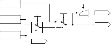
Parameters |
|
|
|
|
Issue 08/02 |
|||
|
|
|
|
|
|
|
|
|
r0056 |
|
CO/BO: Status of motor control |
|
Min: |
- |
|
Level: |
|
|
|
|
Datatype: U16 |
Unit: - |
Def: |
- |
|
3 |
|
|
P-Group: |
CONTROL |
|
Max: |
- |
|
|
|
|
Displays status of motor control (MM420: V/f status), which can be used to diagnose inverter status. |
||||||
|
Bitfields: |
|
|
|
|
|
|
|
|
|
Bit00 |
Init. control finished |
0 |
NO |
|
|
|
|
|
|
|
1 |
YES |
|
|
|
|
|
Bit01 |
Motor demagnetizing finished |
0 |
NO |
|
|
|
|
|
|
|
1 |
YES |
|
|
|
|
|
Bit02 |
Pulses enabled |
0 |
NO |
|
|
|
|
|
|
|
1 |
YES |
|
|
|
|
|
Bit03 |
Voltage soft start select |
0 |
NO |
|
|
|
|
|
|
|
1 |
YES |
|
|
|
|
|
Bit04 |
Motor excitation finished |
0 |
NO |
|
|
|
|
|
|
|
1 |
YES |
|
|
|
|
|
Bit05 |
Starting boost active |
0 |
NO |
|
|
|
|
|
|
|
1 |
YES |
|
|
|
|
|
Bit06 |
Acceleration boost active |
0 |
NO |
|
|
|
|
|
|
|
1 |
YES |
|
|
|
|
|
Bit07 |
Frequency is negative |
0 |
NO |
|
|
|
|
|
|
|
1 |
YES |
|
|
|
|
|
Bit08 |
Field weakening active |
0 |
NO |
|
|
|
|
|
|
|
1 |
YES |
|
|
|
|
|
Bit09 |
Volts setpoint limited |
0 |
NO |
|
|
|
|
|
|
|
1 |
YES |
|
|
|
|
|
Bit10 |
Slip frequency limited |
0 |
NO |
|
|
|
|
|
|
|
1 |
YES |
|
|
|
|
|
Bit11 |
F_out > F_max Freq. limited |
0 |
NO |
|
|
|
|
|
|
|
1 |
YES |
|
|
|
|
|
Bit12 |
Phase reversal selected |
0 |
NO |
|
|
|
|
|
|
|
1 |
YES |
|
|
|
|
|
Bit13 |
I-max controller active |
0 |
NO |
|
|
|
|
|
|
|
1 |
YES |
|
|
|
|
|
Bit14 |
Vdc-max controller active |
0 |
NO |
|
|
|
|
|
|
|
1 |
YES |
|
|
|
|
|
Bit15 |
KIB (Vdc-min control) active |
0 |
NO |
|
|
|
|
Details: |
|
1 |
YES |
|
|
|
|
|
|
|
|
|
|
|
||
|
|
See description of seven-segment display given in the introduction. |
|
|
|
|
||
r0061 |
|
CO: Act. rotor speed |
|
Min: |
- |
|
Level: |
|
|
|
|
Datatype: Float |
Unit: Hz |
Def: |
- |
|
2 |
|
|
P-Group: |
CONTROL |
|
Max: |
- |
|
|
|
|
Displays current speed detected by encoder. |
|
|
|
|
|
|
r0062 |
|
CO: Freq. setpoint |
|
Min: |
- |
|
Level: |
|
|
|
|
Datatype: Float |
Unit: Hz |
Def: |
- |
|
3 |
|
|
P-Group: |
CONTROL |
|
Max: |
- |
|
|
|
|
Displays speed setpoint of vector controller. |
|
|
|
|
|
|
r0063 |
|
CO: Act. frequency |
|
Min: |
- |
|
Level: |
|
|
|
|
Datatype: Float |
Unit: Hz |
Def: |
- |
|
3 |
|
|
|
|
|
||||
|
|
P-Group: |
CONTROL |
|
Max: |
- |
|
|
Displays actual speed.
V/f
P0400
Observer
model
 0
0
 1,2
1,2
Encoder
r0061
|
160 ms |
P1300 |
r0021 |
|
<20
r0063
 ≥ 20
≥ 20
30 |
MICROMASTER 440 Parameter List |
6SE6400-5BB00-0BP0 |
Loading...