


 Loading...
CELSIUS M450/440
TD
Replacements of Parts
System
Replacement of Parts
© Siemens |
2007 |
The reproduction, transmission or use of this document or its contents is not permitted without express written authority. Offenders will be liable for damages. All rights, including rights created by patent grant or registration of a utility model or design, are reserved.
Print No.: |
TD00-400.841.40.02.02 |
English |
Replaces: |
TD00-400.841.40.01.02 |
Doc. Gen. Date: 01.08 |

2 |
Revision / Disclaimer |
Document revision level
The document corresponds to the version/revision level effective at the time of system delivery. Revisions to hardcopy documentation are not automatically distributed.
Please contact your local Siemens office to order current revision levels.
Disclaimer
The installation and service of equipment described herein is to be performed by qualified personnel who are employed by Siemens or one of its affiliates or who are otherwise authorized by Siemens or one of its affiliates to provide such services.
Assemblers and other persons who are not employed by or otherwise directly affiliated with or authorized by Siemens or one of its affiliates are directed to contact one of the local offices of Siemens or one of its affiliates before attempting installation or service procedures.
CELSIUS M450/440 |
TD00-400.841.40.02.02 |
Page 2 of 52 |
Siemens |
|
01.08 |
CS SD SP/CO |
Medical Solutions |
Table of Contents |
3 |
1 _______ General information______________________________________________ 5
Notes . . . . . . . . . . . . . . . . . . . . . . . . . . . . . . . . . . . . . . . . . . . . . . . . . . . . . . . . . . . . . . . . 5
Safety information . . . . . . . . . . . . . . . . . . . . . . . . . . . . . . . . . . . . . . . . . . . . . . . . . . . . 5
Replacement or system upgrades . . . . . . . . . . . . . . . . . . . . . . . . . . . . . . . . . . . . . . . . . . 6 Information about boards . . . . . . . . . . . . . . . . . . . . . . . . . . . . . . . . . . . . . . . . . . . . . . 6
BIOS Installation. . . . . . . . . . . . . . . . . . . . . . . . . . . . . . . . . . . . . . . . . . . . . . . . . . . . . . . . 7
Opening the housing . . . . . . . . . . . . . . . . . . . . . . . . . . . . . . . . . . . . . . . . . . . . . . . . . . . . 8 Variant A (version with knurled screws) . . . . . . . . . . . . . . . . . . . . . . . . . . . . . . . . . . . 8 Variant B (version with a locking lever) . . . . . . . . . . . . . . . . . . . . . . . . . . . . . . . . . . . . 9
Closing the housing . . . . . . . . . . . . . . . . . . . . . . . . . . . . . . . . . . . . . . . . . . . . . . . . . . . . 10 Variant A (version with knurled screws) . . . . . . . . . . . . . . . . . . . . . . . . . . . . . . . . . . 10 Variant B (version with a locking lever) . . . . . . . . . . . . . . . . . . . . . . . . . . . . . . . . . . . 11
Opening the front panel . . . . . . . . . . . . . . . . . . . . . . . . . . . . . . . . . . . . . . . . . . . . . . . . . 12
Closing the front panel . . . . . . . . . . . . . . . . . . . . . . . . . . . . . . . . . . . . . . . . . . . . . . . . . . 13
2 _______ Fans, ventilation duct, crosspiece _________________________________ 14
Front fan . . . . . . . . . . . . . . . . . . . . . . . . . . . . . . . . . . . . . . . . . . . . . . . . . . . . . . . . . . . . . 14 Removing the front fan . . . . . . . . . . . . . . . . . . . . . . . . . . . . . . . . . . . . . . . . . . . . . . . 15 Securing front fan on fan bracket . . . . . . . . . . . . . . . . . . . . . . . . . . . . . . . . . . . . . . . 15 Installing the front fan . . . . . . . . . . . . . . . . . . . . . . . . . . . . . . . . . . . . . . . . . . . . . . . . 17
Side fan . . . . . . . . . . . . . . . . . . . . . . . . . . . . . . . . . . . . . . . . . . . . . . . . . . . . . . . . . . . . . 18 Removing the side fan . . . . . . . . . . . . . . . . . . . . . . . . . . . . . . . . . . . . . . . . . . . . . . . 18 Installing the side fan . . . . . . . . . . . . . . . . . . . . . . . . . . . . . . . . . . . . . . . . . . . . . . . . 19
Ventilation duct and rear fan . . . . . . . . . . . . . . . . . . . . . . . . . . . . . . . . . . . . . . . . . . . . . . 21 Removing the ventilation duct and the rear fan. . . . . . . . . . . . . . . . . . . . . . . . . . . . . 21 Installing the rear fan and the ventilation duct . . . . . . . . . . . . . . . . . . . . . . . . . . . . . 23
Crosspiece . . . . . . . . . . . . . . . . . . . . . . . . . . . . . . . . . . . . . . . . . . . . . . . . . . . . . . . . . . . 25 Removing the crosspiece . . . . . . . . . . . . . . . . . . . . . . . . . . . . . . . . . . . . . . . . . . . . . 25 Installing the crosspiece . . . . . . . . . . . . . . . . . . . . . . . . . . . . . . . . . . . . . . . . . . . . . . 26
3 _______ Power supply __________________________________________________ 27
Preparatory work steps . . . . . . . . . . . . . . . . . . . . . . . . . . . . . . . . . . . . . . . . . . . . . . . . . 27 Changing the power supply . . . . . . . . . . . . . . . . . . . . . . . . . . . . . . . . . . . . . . . . . . . . . . 28 Final work steps . . . . . . . . . . . . . . . . . . . . . . . . . . . . . . . . . . . . . . . . . . . . . . . . . . . . . . . 29
4 _______ Boards _______________________________________________________ 30
Preparatory work steps . . . . . . . . . . . . . . . . . . . . . . . . . . . . . . . . . . . . . . . . . . . . . . . . . 30 Removing a board . . . . . . . . . . . . . . . . . . . . . . . . . . . . . . . . . . . . . . . . . . . . . . . . . . . . . 31 Installing a board . . . . . . . . . . . . . . . . . . . . . . . . . . . . . . . . . . . . . . . . . . . . . . . . . . . . . . 32 Final work steps . . . . . . . . . . . . . . . . . . . . . . . . . . . . . . . . . . . . . . . . . . . . . . . . . . . . . . . 33
5 _______ Drives ________________________________________________________ 34
Preparatory work steps . . . . . . . . . . . . . . |
. . . . . . . . . . . . . . . . . . . . . . . . |
. . . . . . . . . . . 34 |
|
|
|
|
|
Siemens |
TD00-400.841.40.02.02 |
Page 3 of 52 |
CELSIUS M450/440 |
Medical Solutions |
01.08 |
CS SD SP/CO |
|

4 |
Table of Contents |
CD/DVD drive . . . . . . . . . . . . . . . . . . . . . . . . . . . . . . . . . . . . . . . . . . . . . . . . . . . . . . . . . 35 Removing a CD/DVD drive . . . . . . . . . . . . . . . . . . . . . . . . . . . . . . . . . . . . . . . . . . . . 35 Installing a CD/DVD drive . . . . . . . . . . . . . . . . . . . . . . . . . . . . . . . . . . . . . . . . . . . . . 37
Hard disk drive . . . . . . . . . . . . . . . . . . . . . . . . . . . . . . . . . . . . . . . . . . . . . . . . . . . . . . . . 40 Removing a hard disk drive . . . . . . . . . . . . . . . . . . . . . . . . . . . . . . . . . . . . . . . . . . . . 40 Installing a hard disk drive . . . . . . . . . . . . . . . . . . . . . . . . . . . . . . . . . . . . . . . . . . . . . 40
Final work steps . . . . . . . . . . . . . . . . . . . . . . . . . . . . . . . . . . . . . . . . . . . . . . . . . . . . . . . 42
6 _______ Memory module ________________________________________________ 43
Preparatory work steps . . . . . . . . . . . . . . . . . . . . . . . . . . . . . . . . . . . . . . . . . . . . . . . . . . 43 Removing a memory module . . . . . . . . . . . . . . . . . . . . . . . . . . . . . . . . . . . . . . . . . . . . . 44 Installing a memory module . . . . . . . . . . . . . . . . . . . . . . . . . . . . . . . . . . . . . . . . . . . . . . 45 Final work steps . . . . . . . . . . . . . . . . . . . . . . . . . . . . . . . . . . . . . . . . . . . . . . . . . . . . . . . 46
7 _______ Lithium battery _________________________________________________ 47
Changing the lithium battery . . . . . . . . . . . . . . . . . . . . . . . . . . . . . . . . . . . . . . . . . . . . . . 47 Final work steps . . . . . . . . . . . . . . . . . . . . . . . . . . . . . . . . . . . . . . . . . . . . . . . . . . . . . . . 50
8 _______ Changes to previous version _____________________________________ 51
CELSIUS M450/440 |
TD00-400.841.40.02.02 |
Page 4 of 52 |
Siemens |
|
01.08 |
CS SD SP/CO |
Medical Solutions |

General information |
5 |
Notes
Safety information
Please observe the guidelines provided in the safety manual and in the following safety notes.
NOTE |
|
|
The ON/OFF switch does not disconnect the device from the |
||
|
mains voltage. |
|
|
||
|
• To completely disconnect the mains voltage, remove the |
|
|
|
power plug from the power socket. |
|
|
|
|
|
|
NOTE |
Components in the system can get very hot. |
|
|
• Wait a few minutes after switching OFF the system. |
|
|
||
|
|
|
Siemens |
TD00-400.841.40.02.02 |
Page 5 of 52 |
CELSIUS M450/440 |
Medical Solutions |
01.08 |
CS SD SP/CO |
|

6 |
|
|
General information |
Replacement or system upgrades |
|||
|
|
|
|
|
NOTE |
|
Do use orginal Siemens spare parts only! It’s not permitted |
|
|
|
to use other parts! |
|
|
||
|
|
|
Because the device has to be shut down before system |
|
|
|
hardware components can be installed or uninstalled, it is a |
|
|
|
good idea to print out the relevant sections of this chapter. |
|
|
|
It may be necessary to update the BIOS when carrying out a |
|
|
|
system expansion or hardware upgrade. A BIOS CD is avail- |
|
|
|
able for each product (see (BIOS Installation / p. 7)). |
|
|
|
The device must be switched off when system expansions |
|
|
|
are installed or removed, and must not be in energy-saving |
|
|
|
mode. |
|
|
|
Remove the power plug before opening the device. |
|
|
|
If the complete PC tower is replaced, all HW options and |
|
|
|
extensions installed in the defective tower have to be |
|
|
|
swapped from there to the replacement tower. |
|
|
|
|
This chapter provides detailed instructions on modifying your device hardware (e.g. installing boards or drives).
Read the supplied documentation before installing any new drives or boards.
NOTE |
|
|
If it was needed to remove a cable inside the housing, route |
||
|
and fasten them like it was before. |
|
|
||
|
|
|
Information about boards
Take care with the locking mechanisms (catches and centering pins) when you are replacing boards or components on boards.
To prevent damage to the board or the components and conductors on it, please take care when you insert or remove boards. Make sure expansion boards are inserted straight.
Never use sharp objects (screwdrivers) for leverage.
EBoards with electrostatic sensitive devices (ESD) are identified by the label shown.
When you handle boards fitted with ESDs, you must, under all circumstances, observe the following points:
•You must always discharge static build up (e.g. by touching a grounded object) before working.
•The equipment and tools you use must be free of static charges.
•Always hold boards with ESDs by their edges.
•Never touch pins or conductors on boards fitted with ESDs.
CELSIUS M450/440 |
TD00-400.841.40.02.02 |
Page 6 of 52 |
Siemens |
|
01.08 |
CS SD SP/CO |
Medical Solutions |

General information |
7 |
BIOS Installation
 CAUTION
Depending to the system, the BIOS installation may result in a lost of patient data.
Check the specific system documentation for details - concerning the BIOS installation.
If necessary, safe patient data before starting the BIOS installation.
On some systems a BIOS installation requires a complete SW installation.
Siemens |
TD00-400.841.40.02.02 |
Page 7 of 52 |
CELSIUS M450/440 |
Medical Solutions |
01.08 |
CS SD SP/CO |
|

8 |
General information |
Opening the housing
• Switch the device off. The device must not be in energy-saving mode! Please observe all safety guidelines in the "Important notes" chapter.
CPull the power plug out of the mains outlet.
Only insert the power plug after you have closed the housing.
•Remove any connected cables in the unit that obstruct you.
•Place the device in a convenient working position.
Variant A (version with knurled screws)
Fig. 1: Variant A (version with knurled screws)
•Unscrew the two knurled screws (1) on the back of the housing.
Fig. 2: Variant A (remove side cover)
•Slide the side cover approximately 2 cm (a) in the direction of the arrow (1), until the stop.
CELSIUS M450/440 |
TD00-400.841.40.02.02 |
Page 8 of 52 |
Siemens |
|
01.08 |
CS SD SP/CO |
Medical Solutions |
General information |
9 |
•Pull the side cover in the direction of the arrow (2) of the housing.
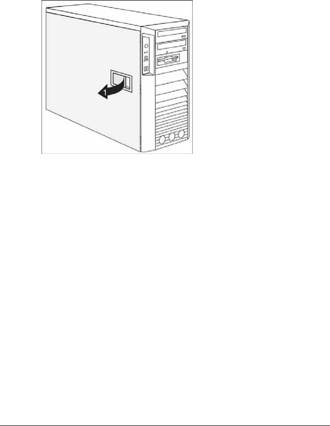
Variant B (version with a locking lever)
Fig. 3: Variant B (version with a locking lever)
•Pull the locking lever (1).
The side panel is now free and can be detached.
Siemens |
TD00-400.841.40.02.02 |
Page 9 of 52 |
CELSIUS M450/440 |
Medical Solutions |
01.08 |
CS SD SP/CO |
|

10 |
General information |
Closing the housing
Variant A (version with knurled screws)
Fig. 4: Variant A (close side cover)
•Hook the side cover into the upper and lower guide rail of the housing in the direction of the arrow (1).
Make sure that the side cover is offset by approximately 2 cm (a).
•Press the side cover onto the housing.
•Push the side cover as far as it will go in the direction of the arrow (2).
Fig. 5: Variant A (tighten the two knurled screws)
•Press the side cover onto the housing (1) at the rear and tighten the two knurled screws
(2) with the other hand.
•Return the system unit to its original position.
•Reconnect any disconnected cables (power cord, cables to external devices, etc.).
CELSIUS M450/440 |
TD00-400.841.40.02.02 |
Page 10 of 52 |
Siemens |
|
01.08 |
CS SD SP/CO |
Medical Solutions |
General information |
11 |
Variant B (version with a locking lever)
Fig. 6: Variant B (closing with a locking lever)
•Hook the side panel into the cutouts in the upper and lower guide rails.
•Close the locking lever in the direction of the arrow (1).
•Return the system unit to its original position.
•Reconnect any disconnected cables (power cord, cables to external devices, etc.).
Siemens |
TD00-400.841.40.02.02 |
Page 11 of 52 |
CELSIUS M450/440 |
Medical Solutions |
01.08 |
CS SD SP/CO |
|
12 |
General information |
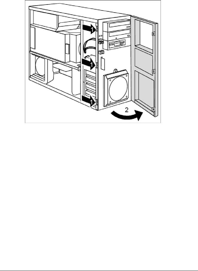
Opening the front panel
Fig. 7: Opening front panel
•Open the housing (Opening the housing / p. 8).
•Detach the three locking tabs on the left side of the front panel (1).
•Fold open the front in the direction of the arrow (2).
•If necessary, detach the hinge on the right-hand side of the front panel from the housing and carefully remove the front panel.
CELSIUS M450/440 |
TD00-400.841.40.02.02 |
Page 12 of 52 |
Siemens |
|
01.08 |
CS SD SP/CO |
Medical Solutions |
General information |
13 |
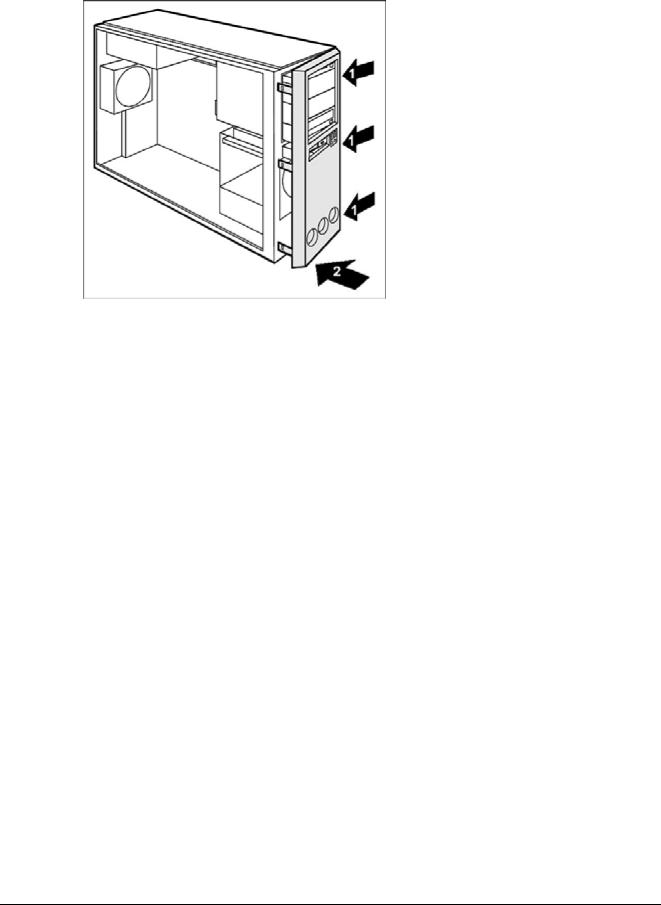
Closing the front panel
Fig. 8: Closing the front panel
•If necessary, hook in the hinge on the right-hand side of the front panel.
•Close the front panel in the direction of the arrow (1) so that the three locking tabs on the left-hand side of the front panel engage (2).
•Close the housing (Closing the housing / p. 10).
Siemens |
TD00-400.841.40.02.02 |
Page 13 of 52 |
CELSIUS M450/440 |
Medical Solutions |
01.08 |
CS SD SP/CO |
|

14 |
Fans, ventilation duct, crosspiece |
Front fan
•Open the housing (Opening the housing / p. 8).
•Open the front panel (Opening the front panel / p. 12).
Fig. 9: Fan connectors on the mainboard
CELSIUS M450/440 |
TD00-400.841.40.02.02 |
Page 14 of 52 |
Siemens |
|
01.08 |
CS SD SP/CO |
Medical Solutions |
Fans, ventilation duct, crosspiece |
15 |
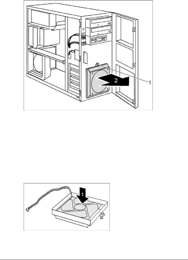
Removing the front fan
Fig. 10: Removing front fan
•Detach the green expansion rivet (1).
•Make sure that the green expansion rivet (1) is not pulled off the fan.
•Tilt the fan toward the front in the direction of the arrow (2) and remove it from the housing.
•Disconnect the fan cable (refer to , (Fig. 9 / p. 14), “Front fan”)).
•Pull the fan cable out of the housing.
•Remove the fan.
Securing front fan on fan bracket
Fig. 11: Fan bracket
•Lay the fan on the fan bracket in the direction of the arrow (1).
Siemens |
TD00-400.841.40.02.02 |
Page 15 of 52 |
CELSIUS M450/440 |
Medical Solutions |
01.08 |
CS SD SP/CO |
|

16 |
|
|
Fans, ventilation duct, crosspiece |
|
|
|
|
|
NOTE |
|
When doing so, ensure the proper rotation and air-flow direc- |
|
|
|
tion. |
|
|
||
|
|
|
Look about the label of the fan as shown in (Fig. 12 / p. 16). |
|
|
|
|
Fig. 12: Air flow of the front fan
•Press the fan firmly into the fan bracket until it is felt to engage.
CELSIUS M450/440 |
TD00-400.841.40.02.02 |
Page 16 of 52 |
Siemens |
|
01.08 |
CS SD SP/CO |
Medical Solutions |
Loading...