


 Loading...
YASKAWA AC Drive - A1000
Spindle Orientation
Custom Software Supplement
Software Number: VSA91009□
Drive Models: 200 V Class, CIMR-AU2A0004□A□-063 to CIMR-AU2A0415□A□-063 400 V Class, CIMR-AU4A0002□A□-063 to CIMR-AU4A0250□A□-063
To properly use the product, read this manual thoroughly and retain for easy reference, inspection, and maintenance. Ensure the end user receives this manual.
MANUAL NO. TM.A1000SW.063

2 |
YASKAWA TM.A1000SW.063 Spindle Orientation A1000 Custom Software Supplement |

Table of Contents
1 PREFACE AND SAFETY . . . . . . . . . . . . . . . . . . . . . . . . . . . . . . . . . . . . . . . . . . . 5 2 SPINDLE ORIENTATION . . . . . . . . . . . . . . . . . . . . . . . . . . . . . . . . . . . . . . . . . . . 6 3 REVISION HISTORY . . . . . . . . . . . . . . . . . . . . . . . . . . . . . . . . . . . . . . . . . . . . . 34
Refer to the A1000 Technical Manual for content not described in this document.
Copyright © 2011 YASKAWA AMERICA, INC.
All rights reserved. No part of this publication may be reproduced, stored in a retrieval system, or transmitted, in any form or by any means, mechanical, electronic, photocopying, recording, or otherwise, without the prior written permission of Yaskawa. No patent liability is assumed with respect to the use of the information contained herein. Moreover, because Yaskawa is constantly striving to improve its high-quality products, the information contained in this manual is subject to change without notice. Every precaution has been taken in the preparation of this manual. Yaskawa assumes no responsibility for errors or omissions. Neither is any liability assumed for damages resulting from the use of the information contained in this publication.
YASKAWA TM.A1000SW.063 Spindle Orientation A1000 Custom Software Supplement |
3 |

This Page Intentionally Blank
4 |
YASKAWA TM.A1000SW.063 Spindle Orientation A1000 Custom Software Supplement |
1 Preface and Safety
1 Preface and Safety
Yaskawa manufactures products used as components in a wide variety of industrial systems and equipment. The selection and application of Yaskawa products remain the responsibility of the equipment manufacturer or end user. Yaskawa accepts no responsibility for the way its products are incorporated into the final system design. Under no circumstances should any Yaskawa product be incorporated into any product or design as the exclusive or sole safety control. Without exception, all controls should be designed to detect faults dynamically and fail safely under all circumstances. All systems or equipment designed to incorporate a product manufactured by Yaskawa must be supplied to the end user with appropriate warnings and instructions as to the safe use and operation of that part. Any warnings provided by Yaskawa must be promptly provided to the end user. Yaskawa offers an express warranty only as to the quality of its products in conforming to standards and specifications published in the Yaskawa manual. NO OTHER WARRANTY, EXPRESS OR IMPLIED, IS OFFERED. Yaskawa assumes no liability for any personal injury, property damage, losses, or claims arising from misapplication of its products.
Applicable Documentation
The following manuals are available for the A1000 Drive:
Custom Software Supplement
SUPPLEMENT
Yaskawa AC Drive - Spindle Orientation A1000 Custom Software Supplement
Manual No: TM.A1000SW.063
Read this manual first. This supplement is an addendum to the A1000 Quick Start Guide and Technical Manual. It lists the effects of this custom software on the parameters in the drive and function descriptions in the manual.
To obtain the supplement access this site: U.S: http://www.yaskawa.com
Yaskawa Drive
Yaskawa AC Drive -
A1000 Quick Start Guide
Yaskawa AC Drive -
A1000 Technical Manual
To obtain instruction manuals for Yaskawa products access these sites: U.S.: http://www.yaskawa.com
Europe: http://www.yaskawa.eu.com Japan: http://www.e-mechatronics.com
Other areas: contact a Yaskawa representative.
For questions, contact the local Yaskawa sales office or the nearest Yaskawa representative.
Supplemental Safety Information
Read and understand this manual and the A1000 Quick Start Guide before installing, operating, or servicing this option unit. Install the drive according to the A1000 Quick Start Guide and local codes. Observe all cautions and warnings in this document and the standard drive technical manuals.
Refer to the A1000 Quick Start Guide and Technical Manual for safety information and to install and start-up the drive.
This document is a supplement to the standard drive technical manual. It describes the effects on the drive parameters and functions with the software installed.
•Custom software is provided to add functionality to a standard drive to enhance or enable use in a specific application.
•The software is loaded to the flash ROM area of the control board, and replaces the standard drive software.
Obtaining Support
When seeking support for a drive with custom software, it is imperative to provide the unique part number shown on the drive nameplate. The software is flashed to the control board memory and the operation of parameters, functions, and monitors are different than the standard drive software, as described herein.
Refer to Yaskawa office locations listed on the back cover of this manual.
YASKAWA TM.A1000SW.063 Spindle Orientation A1000 Custom Software Supplement |
5 |
2 Spindle Orientation
2Spindle Orientation
Overview
The target applications for this function are on equipment that must stop in specific positions including tool changing for machine tool spindles and die changing for punch/stamping presses. This software also provides for high frequency operation with automatic switchover to closed-loop operation at low speed.
Applicable Models
This Spindle Orient software is available for the drive models listed in Table 1.
|
Table 1 Applicable Models |
|
|
|
|
|
|
Voltage Class |
Model |
Software Version |
|
200 V |
CIMR-AU2A0004 A -063 to CIMR-AU2A0415 A -063 |
VSA910090 |
|
400 V |
CIMR-AU4A0002 A -063 to CIMR-AU4A0250 A -063 |
||
|
Basic Concepts and Principles
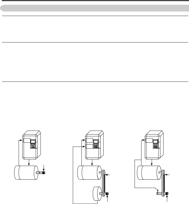
This orientation software allows an A1000 drive to repeatedly stop a machine at a certain point in its rotational cycle. This is accomplished by means of an orientation encoder directly coupled to the machine part to be positioned. A simple example is to think of the hands on a clock. If the orientation encoder is mounted to the motor shaft, this software can stop the motor so that the spindle stops at the 3 o'clock position every time. Application configurations are outlined in Figure 1. For configurations other than those outlined, contact Yaskawa Application Engineering before applying this software.
Configuration 1: Direct Drive |
Configuration 2: Indirect Drive with |
Configuration 3: Indirect Drive with |
|
Orientation Encoder |
Proximity Sensor |
||
|
PG-X3 |
CN5-C |
|
Motor Encoder |
Machine |
|
Motor
Ch A/B/Z
|
|
PG-X3 |
|
|
PG-X3 |
|
CN5-B |
|
PG-X3 |
|
|
|
|
|
CN5-C |
|
|
CN5-C |
|
|
Orientated |
|
|
|
|
|
|
Machine Part |
|
|
|
|
|
|
Motor |
Encoder |
Machine |
Drivetrain |
Motor Encoder |
Machine |
Drivetrain |
Motor |
Motor |
|||||
|
(Gear Ratio) |
|
(Gear Ratio) |
|||
|
|
|
|
|
||
Ch A/B |
|
|
Ch A/B |
|
|
|
|
|
|
Ch A/B/Z |
|
|
|
|
|
|
Orientation Encoder |
|
Proximity |
|
|
|
|
|
Sensor |
|
|
|
|
|
|
|
Ch Z |
|
|
|
|
Orientated |
|
|
Orientated |
|
|
|
Machine Part |
|
|
Machine Part |
Figure 1 Spindle Orientation Hardware Configurations
6 |
YASKAWA TM.A1000SW.063 Spindle Orientation A1000 Custom Software Supplement |

2 Spindle Orientation
Direct Drive
In the first configuration, the drive motor directly drives the machine part being oriented (positioned). When using this method, the motor encoder is used for both closed loop vector motor control and for orientation. This encoder must have a C or Z channel which provides a “marker” or “index” pulse with every rotation. If the encoder does not have a C/Z channel, an external marker pulse can be implemented as outlined in Encoder (PG) Option Card Configuration and Wiring on page 29. Additionally, a PG-X3 or PG-B3 encoder (PG) feedback option card is required to connect the encoder to the drive.
Indirect Drive with Orientation Encoder
When the motor and the machine part to be oriented (positioned) are connected through a drive train with a constant ratio, two encoders are required. The first encoder is mounted on the driven motor, and the second, an orientation encoder, is mounted on the machine part to be oriented. The orientation encoder must have a C or Z channel which provides a “marker” or “index” pulse with every rotation. If the encoder does not have a C/Z channel, an external marker pulse can be implemented as outlined in Encoder (PG) Option Card Configuration and Wiring on page 29. The motor encoder does not need to have a C/Z channel. Two encoder (PG) feedback option cards are required for this setup.
Indirect Drive with Proximity Sensor
When the motor and the spindle are connected through a drive train and the spindle does not have its own encoder, a proximity sensor may be used. The proximity sensor is connected as an external marker pulse; therefore this configuration requires only one PG-X3 encoder (PG) feedback option card. In this configuration, the gear ratio of the drive train must be expressed as the number of revolutions of the motor per revolution of the spindle.
Online Control Mode Switch Function
This software can switch between Closed Loop Vector Control and V/f Control during run. The 1000 Hz software is limited to V/f control mode above 400 Hz, it is possible to change tools without stopping the machine if the inverter switches to Closed Loop Vector Control for Position Control at Low-Speed. At Low-Speed the inverter can be set to operate in Closed Loop Vector Control and automatically switch to V/f Control when the output is above the frequency which is set.
Changes from the Standard Product
•Second PG Channel Parameters F1-30 through F1-37 are always visible whether or not digital selection H1-0 =16 (Motor 2 Select) is programmed.
•Only two Control Modes can be set in A1-02 and E3-01, 0:V/f and 3:Closed-Loop Vector.
•Only two Auto-Tuning Mode Selections are available, 0:Rotational Auto-Tuning and 2:Stationary Auto-Tuning for Line-to-Line Resistance.
Deleted Functions
Certain functions in the standard software of A1000 are deleted in this Orientation software. Deleted functions are listed in Table 2.
Table 2 Deleted Functions
|
Function Name |
|
Speed Search (all methods) |
KEB Function |
Fault Restart |
High Slip Braking (HSB) |
Overexcitation Braking |
Field Weakening Function |
Energy Savings |
Droop Control |
Field Forcing Function |
Frequency Reference Lower Limit |
Feed Forward Control |
DC Injection Braking Current Setting in V/f |
Torque Detection |
Stall Prevention Selection during Acceleration |
Stall Prevention Selection during Run |
YASKAWA TM.A1000SW.063 Spindle Orientation A1000 Custom Software Supplement |
7 |

2Spindle Orientation
Limitations
•The multi-function digital input function Motor 2 Select (H1- = 16) and Encoder Option Card Setting F1-30 have restrictions when used in Closed Loop Vector control mode with an additional orientation encoder. Refer to Table 15 on page 16 and Table 17 on page 31.
•Applications using Configuration 2 and Motor 1/Motor 2 switchover must use a motor encoder and an orientation encoder of the same PPR.
•DriveWorks EZ functionality is not fully supported when using this software. If DriveWorks EZ support is required, please contact Yaskawa Application Engineering.
•PG Encoder PPR parameters F1-01 and F1-31 are limited to PPR of 8 to 16384 PPR (32 to 65536 counts per revolution).
•Orient functionality is disabled when the run command comes from the Local Operator (b1-02 = 0).
•Since all forms of speed search are disabled, the stopping method Coast to Stop (b1-03 = 1) causes inconsistent operation of the spindle orient routine if an orient digital input is closed while the drive is coasting. This may include but is not limited to overvoltage trips and faster than expected deceleration.
•Disabling reverse operation by setting Reverse Operation Selection parameter b1-04=1 prohibits the orient function from maintaining position.
•Frequency Upper Limit parameter d2-01 prevents the spindle orient function from operating if the frequency limit is set at or below the P1-02 Creep Speed.
•Orient digital inputs are disabled when Forward or Reverse Jog commands (H1-0 = 12 or 13) are active.
•Orient digital inputs are disabled when Control Mode Switchover Prevention digital input H1-0 = 50 is closed while the drive is not running.
Related Parameters and Functions
The legend below is used in this section to indicate which parameters are available in which control modes. The parameter tables in this section are used to set up the drive for operation with the software.
! "
|
|
|
|
||
|
|
|
|
||
|
||
|
||
|
|
|
|
|
Note: Chinese language support is added to certain parameters and functions. Refer to References on page 31 for the parameters and functions with Chinese language support.
Table 3 Modified Parameters
|
MEMOBUS/ |
Name |
|
|
Default |
Change |
Control Method/ |
|
No. |
Modbus |
Description |
Range |
During |
||||
Digital Operator Display |
Value |
Access Level |
||||||
|
Address |
|
|
Run |
||||
|
|
|
|
|
|
|||
F1-01 |
0380h |
PG 1 Pulses Per Revolution |
Sets the number of encoder pulses per revolution |
8 to 16384 PPR |
1024 PPR |
No |
– – – Y– – N |
|
PG1 Pulses/Rev |
for the encoder on channel 1. |
|||||||
|
|
|
|
|
|
|||
|
|
|
|
|
|
|
|
|
|
|
|
Specifies the drive port for the PG option card used |
|
|
|
|
|
|
|
|
for Motor 2. |
|
|
|
|
|
|
|
PG Option Card Port for Motor 2 |
0: CN5-C |
|
|
|
|
|
F1-30 |
03AAh |
Selection |
0 to 1 |
0 |
No |
– – – Y– – N |
||
1: CN5-B |
||||||||
|
|
Mtr2 PG Port Sel |
|
|
|
|
||
|
|
|
|
|
|
|
||
|
|
|
Note: This parameter is available without a digital |
|
|
|
|
|
|
|
|
input H1-0 programmed to 16h (Motor 2 Select). |
|
|
|
|
8 |
YASKAWA TM.A1000SW.063 Spindle Orientation A1000 Custom Software Supplement |
|
|
|
|
|
2 |
Spindle Orientation |
||
|
|
|
|
|
|
|
|
|
|
MEMOBUS/ |
Name |
|
|
Default |
|
Change |
Control Method/ |
No. |
Modbus |
Description |
Range |
|
During |
|||
Digital Operator Display |
Value |
|
Access Level |
|||||
|
Address |
|
|
|
Run |
|||
|
|
|
|
|
|
|
||
|
|
|
Sets the number of encoder pulses per revolution |
|
|
|
|
|
|
|
PG 2 Pulses Per Revolution |
for the encoder on channel 2. |
8 to |
|
|
|
|
F1-31 |
03B0h |
|
1024 PPR |
|
No |
– – – Y– – N |
||
PG2 Pulses/Rev |
Note: This parameter is available without a digital |
16384 PPR |
|
|||||
|
|
|
|
|
|
|||
|
|
|
input H1-0 programmed to 16h |
|
|
|
|
|
|
|
|
(Motor 2 Select). |
|
|
|
|
|
|
|
|
Determines the direction indicated by the pulses |
|
|
|
|
|
|
|
|
from the PG feedback encoder for motor 2. |
|
|
|
|
|
F1-32 |
03B1h |
PG2 Rotation Selection |
0: Pulse A Leads |
0 to 1 |
0 |
|
No |
– – – Y– – N |
PG2 Rotation Sel |
1: Pulse B Leads |
|
||||||
|
|
|
|
|
|
|
||
|
|
|
This parameter is available without a digital input |
|
|
|
|
|
|
|
|
H1-0 programmed to 16h (Motor 2 Select). |
|
|
|
|
|
|
|
PG2 Division Rate for Pulse |
Sets the ratio between the pulse input and the pulse |
|
|
|
|
|
|
|
output of a PG option card. |
|
|
|
|
|
|
F1-35 |
03BEh |
Monitor |
1 to 132 |
1 |
|
No |
– – – Y– – N |
|
This parameter is available without a digital input |
|
|||||||
|
|
PG2 Output Ratio |
|
|
|
|
|
|
|
|
H1-0 programmed to 16h (Motor 2 Select). |
|
|
|
|
|
|
|
|
|
|
|
|
|
|
|
|
|
|
|
|
|
|
|
|
|
|
|
Sets whether the drive detects a fault when a |
|
|
|
|
|
|
|
|
PG-X3 card is disconnected. |
|
|
|
|
|
|
|
PG Option Card Disconnect |
0: Disabled |
|
|
|
|
|
F1-36 |
03B5h |
Detection 2 |
1: Enabled |
0 to 1 |
1 |
|
No |
– – – Y– – N |
|
|
PGCardDisconDet1 |
This parameter is available without a digital |
|
|
|
|
|
|
|
|
|
|
|
|
|
|
|
|
|
input H1-0x programmed to 16h |
|
|
|
|
|
|
|
|
(Motor 2 Select). |
|
|
|
|
|
|
|
|
Determines how Stall Prevention works during |
|
|
|
|
|
|
|
|
Run. |
|
|
|
|
|
|
|
|
The parameter default is changed to 0: Disabled. |
|
|
|
|
|
|
|
|
0: Disabled |
|
|
|
|
|
|
|
Stall Prevention Selection during |
1: General Purpose |
|
|
|
|
|
|
|
2: Intelligent |
|
|
|
|
|
|
L3-04 |
0492h |
Deceleration |
0 to 5 |
0 |
|
No |
– – – Y– – Y |
|
3: Stall Prevention w/Braking Resistor |
|
|||||||
|
|
StallP Decel Sel |
|
|
|
|
|
|
|
|
4: Overexcitation Deceleration |
|
|
|
|
|
|
|
|
|
|
|
|
|
|
|
|
|
|
5: Overexcitation Deceleration 2 |
|
|
|
|
|
|
|
|
Note: Enabling stall prevention extends the decel |
|
|
|
|
|
|
|
|
time. Other modes such as Intelligent may cause |
|
|
|
|
|
|
|
|
unintended operation during orient, including |
|
|
|
|
|
|
|
|
oscillation and inability to maintain position. |
|
|
|
|
|
|
|
|
Parameter S1-01 is used to enable and disable On |
|
|
|
|
|
S1-01 |
680h |
On-Delay Compensation Selection |
Delay Compensation. |
0 to 1 |
1 |
|
No |
– – – Y– – Y |
|
|
|||||||
OnDelay Comp Sel |
0: Disabled |
|
||||||
|
|
|
|
|
|
|
||
|
|
|
|
|
|
|
|
|
|
|
|
1: Enabled |
|
|
|
|
|
|
|
|
|
|
|
|
|
|
|
|
|
Normally there is no need to change S1-03 from its |
|
|
|
|
|
|
|
|
default setting. If there is a problem with output |
|
|
|
|
|
|
|
|
voltage weakening when attempting to compensate |
|
|
|
|
|
S1-03 |
682h |
Extended Current Sampling Mode |
for output current distortion as the motor reaches |
0 to 1 |
1 |
|
No |
– – – Y– – Y |
1000 Hz while decoupled from the load during a |
|
|||||||
Extend I Sample |
|
|||||||
|
|
test run, then try setting S1-03 = 1. |
|
|
|
|
|
|
|
|
|
|
|
|
|
|
|
|
|
|
0: Disabled |
|
|
|
|
|
|
|
|
1: Enabled |
|
|
|
|
|
|
|
|
Sets the frequency of switching from Closed Loop |
|
|
|
|
|
|
|
|
Vector Control to V/f Control. |
|
|
|
|
|
|
|
Control Mode Switchover |
This function is disabled when 0 or 400 Hz is set, |
|
|
|
|
|
|
|
the inverter runs as V/f Control when 0 is set and |
|
|
|
|
|
|
S2-01 |
691h |
Frequency |
Closed Loop Vector Control when 400 Hz is set. |
0 to 400 Hz |
400 |
|
No |
– – – Y– – N |
|
|
HF SwOver Freq |
However, OPE21 occurs when the relations among |
|
|
|
|
|
|
|
|
Control Mode Switch Frequency (S2-01) and PG |
|
|
|
|
|
|
|
|
Pulse per Revolution (F1-01) and Numbers of |
|
|
|
|
|
|
|
|
Motor Poles (E2-04) are set higher than the |
|
|
|
|
|
|
|
|
permissible input frequency of PG option. |
|
|
|
|
|
|
|
Control Mode Switchover |
Sets the hysteresis width of Control Mode Switch. |
|
|
|
|
|
S2-02 |
692h |
Bandwidth |
Increase if shock occurs during Control Mode |
2 to 100 Hz |
20 |
|
No |
– – – Y– – N |
|
|
HF CtrlMode SwBW |
switching. |
|
|
|
|
|
|
|
|
|
|
|
|
|
|
YASKAWA TM.A1000SW.063 Spindle Orientation A1000 Custom Software Supplement |
9 |

2 Spindle Orientation
|
MEMOBUS/ |
Name |
|
|
Default |
Change |
Control Method/ |
|
No. |
Modbus |
Description |
Range |
During |
||||
Digital Operator Display |
Value |
Access Level |
||||||
|
Address |
|
|
Run |
||||
|
|
|
|
|
|
|||
|
|
|
Sets the gain for the Motor Slip Compensation at |
|
|
|
|
|
|
|
|
Hi-Speed Function. Although this parameter rarely |
|
|
|
|
|
|
|
High Frequency Slip |
needs to be changed, adjustments might be needed |
|
|
|
|
|
|
|
under the following circumstances: |
|
|
|
|
||
S2-05 |
695h |
Compensation Gain |
0.0 to 2.5 |
0.0 |
Yes |
– – – Y– – N |
||
If the motor at constant speed is slower than the |
||||||||
|
|
HF SlipComp Gain |
|
|
|
|
||
|
|
frequency reference, increase S2-05. |
|
|
|
|
||
|
|
|
|
|
|
|
||
|
|
|
If the motor at constant speed is faster than the |
|
|
|
|
|
|
|
|
frequency reference, decrease S2-05. |
|
|
|
|
|
|
|
|
Sets the filter on the output side of the Slip |
|
|
|
|
|
|
|
|
Compensation at Hi-Speed Function. Although this |
|
|
|
|
|
|
|
High Frequency Slip |
parameter rarely needs to be changed, adjustments |
|
|
|
|
|
|
|
might be needed under the following |
|
|
|
|
||
S2-06 |
696h |
Compensation Primary Delay Time |
0 to 10000 ms |
2000 |
Yes |
– – – Y– – N |
||
circumstances: |
||||||||
|
|
HF SlipComp Time |
-Decrease the setting when the slip compensation |
|
|
|
|
|
|
|
|
|
|
|
|
||
|
|
|
response is too slow. |
|
|
|
|
|
|
|
|
-Increase this setting when speed is unstable. |
|
|
|
|
|
|
|
High Frequency Slip |
Sets the upper limit for the Slip Compensation at |
0 to 250% |
200 |
No |
– – – Y– – N |
|
S2-07 |
697h |
Compensation Limit |
Hi-Speed Function as a percentage of the motor |
|||||
|
|
HF SlipComp Lim |
rated slip (E2-02). |
|
|
|
|
|
|
|
|
|
|
|
|
|
|
|
|
|
When Slip Compensation during Regeneration at |
|
|
|
|
|
|
|
|
Hi-Speed is activated and a regenerative load is |
|
|
|
|
|
|
|
High Frequency Slip |
applied, it might be necessary to use a dynamic |
|
|
|
|
|
|
|
braking option (braking resistor, braking resistor |
|
|
|
|
||
S2-08 |
698h |
Compensation Selection During |
unit, or braking unit). |
0 to 2 |
0 |
No |
– – – Y– – N |
|
Regeneration |
|
|||||||
|
|
|
|
|
|
|
||
|
|
HF SlipCompRegen |
0: Disabled |
|
|
|
|
|
|
|
|
1: Enabled (6 Hz and Above) |
|
|
|
|
|
|
|
|
2: Enabled |
|
|
|
|
|
|
|
|
(Compensation provided wherever possible) |
|
|
|
|
|
|
|
|
Sets the frequency of switching from Closed Loop |
|
|
|
|
|
|
|
|
Vector Control to V/f Control for Motor 2 |
|
|
|
|
|
|
|
|
This function is disabled when 0 or 400Hz is set, |
|
|
|
|
|
|
|
Motor 2 Control Mode Switchover |
the inverter runs as V/f Control when 0 is set, and |
|
|
|
|
|
S2-11 |
699h |
Frequency |
Closed Loop Vector Control when 400Hz is set. |
0 to 400 Hz |
400 |
No |
– – – Y– – N |
|
|
|
HF SwOver Freq 2 |
However, OPE21 occurs when the relations among |
|
|
|
|
|
|
|
|
Control Mode Switch Frequency (S2-11) and PG |
|
|
|
|
|
|
|
|
Pulse per Revolution (F1-31) and Numbers of |
|
|
|
|
|
|
|
|
Motor Poles (E4-04) are set higher than the |
|
|
|
|
|
|
|
|
permissible input frequency of PG option. |
|
|
|
|
|
|
|
|
Sets the hysteresis width of Control Mode Switch |
|
|
|
|
|
S2-12 |
69Ah |
Motor 2 Control Mode Switchover |
for Motor 2. |
2 to 100 Hz |
20 |
No |
– – – Y– – N |
|
Bandwidth |
Increase if shock occurs during Control Mode |
|||||||
|
|
|
|
|
|
|||
|
|
HF CtrlModeSwBW2 |
switching. |
|
|
|
|
|
|
|
|
|
|
|
|
|
|
|
|
|
Sets the gain for the Motor Slip Compensation at |
|
|
|
|
|
|
|
|
Hi-Speed Function for Motor 2. Although this |
|
|
|
|
|
|
|
|
parameter rarely needs to be changed, adjustments |
|
|
|
|
|
|
|
Motor 2 High Frequency Slip |
might be needed under the following |
0.0 to 2.5 |
0.0 |
Yes |
– – – Y– – N |
|
S2-15 |
69Dh |
Compensation Gain |
circumstances: |
|||||
|
|
HF SlipCompGain2 |
-If the motor at constant speed is slower than the |
|
|
|
|
|
|
|
|
frequency reference, increase S2-15. |
|
|
|
|
|
|
|
|
-If the motor at constant speed is faster than the |
|
|
|
|
|
|
|
|
frequency reference, decrease S2-15. |
|
|
|
|
|
|
|
|
Sets the filter on the output side of the Slip |
|
|
|
|
|
|
|
|
Compensation at Hi-Speed Function for Motor 2. |
|
|
|
|
|
|
|
Motor 2 High Frequency Slip |
Although this parameter rarely needs to be |
|
|
|
|
|
|
|
changed, adjustments might be needed under the |
|
|
|
|
||
S2-16 |
69Eh |
Compensation Primary Delay Time |
0 to 10000 ms |
2000 |
Yes |
– – – Y– – N |
||
|
|
HF SlipCompTime2 |
following circumstances: |
|
|
|
|
|
|
|
-Decrease the setting when the slip compensation |
|
|
|
|
||
|
|
|
|
|
|
|
||
|
|
|
response is too slow. |
|
|
|
|
|
|
|
|
-Increase this setting when speed is unstable. |
|
|
|
|
|
|
|
Motor 2 High Frequency Slip |
Sets the upper limit for the Slip Compensation at |
|
|
|
|
|
S2-17 |
69Fh |
Compensation Limit |
Hi-Speed Function for Motor 2 as a percentage of |
0 to 250% |
200 |
No |
– – – Y– – N |
|
|
|
HF SlipComp Lim2 |
the motor rated slip (E4-02). |
|
|
|
|
|
|
|
|
|
|
|
|
|
10 |
YASKAWA TM.A1000SW.063 Spindle Orientation A1000 Custom Software Supplement |
|
|
|
|
|
2 |
Spindle Orientation |
||
|
|
|
|
|
|
|
|
|
|
MEMOBUS/ |
Name |
|
|
Default |
|
Change |
Control Method/ |
No. |
Modbus |
Description |
Range |
|
During |
|||
Digital Operator Display |
Value |
|
Access Level |
|||||
|
Address |
|
|
|
Run |
|||
|
|
|
|
|
|
|
||
|
|
|
When Slip Compensation during Regeneration at |
|
|
|
|
|
|
|
|
Hi-Speed is activated and a regenerative load is |
|
|
|
|
|
|
|
|
applied, it might be necessary to use a dynamic |
|
|
|
|
|
|
|
Motor 2 High Frequency Slip |
braking option (braking resistor, braking resistor |
|
|
|
|
|
S2-18 |
6A0h |
Compensation During |
unit, or braking unit). |
0 to 2 |
0 |
|
No |
– – – Y– – N |
Regeneration Selection |
|
|
||||||
|
|
|
|
|
|
|
|
|
|
|
HF SlipCompRgn 2 |
0: Disabled |
|
|
|
|
|
|
|
|
1: Enabled (6 Hz and Above) |
|
|
|
|
|
|
|
|
2: Enabled |
|
|
|
|
|
|
|
|
(Compensation provided wherever possible) |
|
|
|
|
|
Table 4 Additional Parameters
|
MEMOBUS/ |
Name |
|
|
Default |
Change |
Control Method/ |
|
No. |
Modbus |
Description |
Range |
During |
||||
Digital Operator Display |
Value |
Access Level |
||||||
|
Address |
|
|
Run |
||||
|
|
|
|
|
|
|||
|
|
|
This parameter sets the frequency at which the |
|
|
|
|
|
|
|
|
drive switches to the Orient Deceleration Time |
|
|
|
|
|
|
|
|
(P1-12) and Orient ASR settings (P2-10 and P2- |
|
|
|
|
|
P1-01 |
0600h |
Orient Speed |
11) when these parameters are enabled. |
0.00 to 200.00 Hz |
20.00 |
No |
– – – Y– – N |
|
|
||||||||
Orient Speed |
Note: P1-01 must be set such that it is not greater |
|||||||
|
|
|
|
|
|
|||
|
|
|
|
|
|
|
||
|
|
|
than the control modes switchover frequency: |
|
|
|
|
|
|
|
|
((S2-01 – S2-02) > P1-01). P1-01 must also be set |
|
|
|
|
|
|
|
|
lower than the Maximum Output Frequency E1-04. |
|
|
|
|
|
|
|
Creep Speed |
This parameter sets the speed at which the drive |
|
|
|
|
|
P1-02 |
0601h |
locates the marker pulse. This is also the speed at |
0.10 to 10.00 Hz |
2.00 |
No |
– – – Y– – N |
||
Creep Speed |
||||||||
|
|
which s-curves are disabled. |
|
|
|
|
||
|
|
|
|
|
|
|
||
|
|
|
|
|
|
|
|
|
|
|
|
This parameter sets the number of quadrature |
|
|
|
|
|
|
|
Creep Distance |
encoder counts around the orientation position |
|
|
|
|
|
P1-03 |
0602h |
where the frequency reference is allowed to drop |
0 to 2000 Cnts |
200 |
No |
– – – Y– – N |
||
Creep Distance |
||||||||
|
|
below the P1-02 Creep Speed. Within the Creep |
|
|
|
|
||
|
|
|
|
|
|
|
||
|
|
|
Distance, the drive accel/decel times are set to 0. |
|
|
|
|
|
|
|
|
|
|
|
|
|
|
|
|
Approach Speed |
This parameter sets the minimum speed that the |
|
|
|
|
|
P1-04 |
0603h |
drive operates at until it reaches the P1-05 ORT Set |
0.00 to 1.00 Hz |
0.10 |
No |
– – – Y– – N |
||
Approach Speed |
||||||||
|
|
Window. |
|
|
|
|
||
|
|
|
|
|
|
|
||
|
|
|
|
|
|
|
|
|
|
|
|
This parameter sets the initial window around the |
|
|
|
|
|
|
|
|
orientation position that activates the Orient |
|
|
|
|
|
|
|
|
Complete digital output. The Orient Complete |
|
|
|
|
|
|
|
Orientation Complete Detection Set |
digital output (H2- = 40) closes when the |
|
|
|
|
|
P1-05 |
0604h |
Window |
encoder quadrature count is within the P1-05 |
0 to 100 Cnts |
25 |
No |
– – – Y– – N |
|
|
|
ORT Set Window |
window of the orientation offset and after the P1-07 |
|
|
|
|
|
|
|
|
delay time has expired. |
|
|
|
|
|
|
|
|
Note: Counts = Encoder PPR x 4. |
|
|
|
|
|
|
|
|
This parameterr sets, in quadrature encoder counts, |
|
|
|
|
|
|
|
Orientation Complete Detection |
the window around the orient position that keeps the |
|
|
|
|
|
|
|
Orient Complete digital output (H2- = 40) |
|
|
|
|
||
P1-06 |
0605h |
Reset Window |
0 to 100 Cnts |
0 |
No |
– – – Y– – N |
||
closed. |
||||||||
|
|
ORT Rst Window |
|
|
|
|
||
|
|
|
Note: Counts = Encoder PPR x 4. |
|
|
|
|
|
|
|
|
This parameter sets the delay time from when the |
|
|
|
|
|
P1-07 |
0606h |
Orientation Set Time |
P1-05 Orient Set window is satisfied and the |
0 to 1000 ms |
10 |
No |
– – – Y– – N |
|
ORT Set Time |
Orientation Complete digital output (H2- = 40) |
|||||||
|
|
|
|
|
|
|||
|
|
|
closes. |
|
|
|
|
|
|
|
|
|
|
|
|
|
|
P1-08 |
0607h |
Positioning Proportional Gain |
This parameter sets the proportional gain used for |
0.10 to 20.00 |
1.00 |
No |
– – – Y– – N |
|
Pos P Gain |
the position controller. |
|||||||
|
|
|
|
|
|
|||
|
|
|
|
|
|
|
|
|
|
|
|
This parameter sets the minimum orientation |
|
|
|
|
|
|
|
Orientation Compensation Distance |
distance between the orientation encoder marker |
|
|
|
|
|
P1-09 |
0608h |
pulse at or below P1-02 and the desired orientation |
0 to 100% |
50% |
No |
– – – Y– – N |
||
|
|
Orient Comp Dist |
offset. This distance is expressed as a percentage of |
|
|
|
|
|
|
|
|
the active encoder PPR (e.g. F1-01 x P1-09). |
|
|
|
|
|
|
|
|
|
|
|
|
|
YASKAWA TM.A1000SW.063 Spindle Orientation A1000 Custom Software Supplement |
11 |
Loading...