


Generator
OWNER’S MANUAL
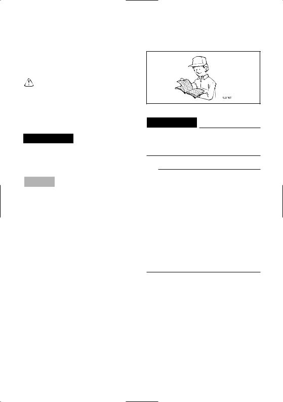
Read this manual carefully before operating this machine.
EF2000iS
LIT-19626-01-53
7DK-28199-10
 Read this manual carefully befor operating this machine.This manual should stay with this machine if it is sold.

AE00002
INTRODUCTION
Congratulations on your purchase of your new Yamaha.
This manual will provide you with a good basic understanding of the operation and maintenance of this machine.
If you have any questions regarding the operation or maintenance of your machine, please consult a Yamaha dealer.
AE00022
EF2000iS
OWNER’S MANUAL
© 2009 by Yamaha Motor Corporation, U.S.A. 1st Edition, January 2009
All rights reserved.
Any reprinting or unauthorized use without the written permission of Yamaha Motor Corporation, U.S.A. is expressly prohibited.
Printed in Japan
P/N LIT-19626-01-53
IMPOTANT MANUAL INFORMATION
Particularly important information is distinguished in this manual by the following notations.
This is the safety alert symbol. It is used to alert you to potential personal injury hazards. Obey all safety messages that follow this symbol to avoid possible injury or death.
 WARNING
A WARNING indicates a hazardous situation which, if not avoided, could result in death or serious injury.
NOTICE
A NOTICE indicates special precautions that must be taken to avoid damage to the machine or other property.
TIP
A TIP provides key information to make procedures easier or clearer.
AE00032
 WARNING
PLEASE READ AND UNDERSTAND THIS MANUAL COMPLETELY BEFORE OPERATING THE MACHINE.
TIP
9Yamaha continually seeks advancements in product design and quality. Therefore, while this manual contains the most current product information available at the time of printing, there may be minor discrepancies between your engine and this manual. If there is any question concerning this manual, please consult a Yamaha dealer.
9This manual should be considered a permanent part of this engine and should remain with this engine when resold.
*Product and specifications are subject to change without notice.

AE00041 |
|
CONTENTS |
|
SAFETY INFORMATION......................... |
1 |
EXHAUST FUMES ARE |
|
POISONOUS........................................ |
1 |
FUEL IS HIGHLY FLAMMABLE AND |
|
POISONOUS........................................ |
1 |
ENGINE AND MUFFLER MAY BE |
|
HOT ...................................................... |
1 |
ELECTRIC SHOCK PREVENTION ..... |
2 |
CONNECTION NOTES ........................ |
3 |
CONNECTION ..................................... |
3 |
EXTENSION CORD NOTES................ |
3 |
LOCATION OF IMPORTANT |
|
LABELS................................................... |
4 |
DESCRIPTION ........................................ |
6 |
Control Panel........................................ |
6 |
CONTROL FUNCTION............................ |
7 |
Engine switch ....................................... |
7 |
Oil warning light (Red).......................... |
7 |
DC protector ......................................... |
7 |
Economy control switch........................ |
8 |
AC pilot light (Green)............................ |
8 |
Overload indicator light (Red) .............. |
9 |
Fuel tank cap........................................ |
9 |
Fuel tank cap air vent knob ................ |
10 |
Fuel cock knob ................................... |
10 |
Ground (Earth) terminal ..................... |
10 |
Twin Tech ............................................ |
10 |
PREPARATION ..................................... |
11 |
Fuel..................................................... |
11 |
Engine oil............................................ |
12 |
PRE-OPERATION CHECK ................... |
13 |
Pre-operation check ........................... |
13 |
OPERATION .......................................... |
14 |
Starting the engine ............................. |
14 |
Stopping the engine ........................... |
16 |
Connection ......................................... |
17 |
Battery charging ................................. |
18 |
Application range................................ |
20 |
PERIODIC MAINTENANCE.................. |
21 |
Maintenance chart.............................. |
21 |
Spark plug inspection......................... |
23 |
Carburetor adjustment........................ |
24 |
Engine oil replacement....................... |
24 |
Air filter ............................................... |
26 |
Muffler screen and spark arrester ...... |
27 |
Fuel tank filter..................................... |
29 |
STORAGE ............................................. |
30 |
Drain the fuel ...................................... |
30 |
Engine ................................................ |
32 |
TROUBLESHOOTING........................... |
33 |
Engine won’t start............................... |
33 |
Generator won’t produce power ......... |
34 |
SPECIFICATIONS ................................. |
36 |
Dimensions......................................... |
36 |
Engine ................................................ |
36 |
Generator ........................................... |
36 |
CONSUMER INFORMATION................ |
37 |
Identification number records ............. |
37 |
Machine identification......................... |
37 |
LIMITED WARRANTY (EFAND |
|
EDL-SERIES) ........................................ |
38 |
EXHAUST EMISSION CONTROL |
|
SYSTEM AND COMPONENTS ......... |
40 |
WIRING DIAGRAM ............................... |
41 |
7DK-001
7DK-002
7DK-003
7DK-004
7DK-005
AE00071
SAFETY INFORMATION
AE00072
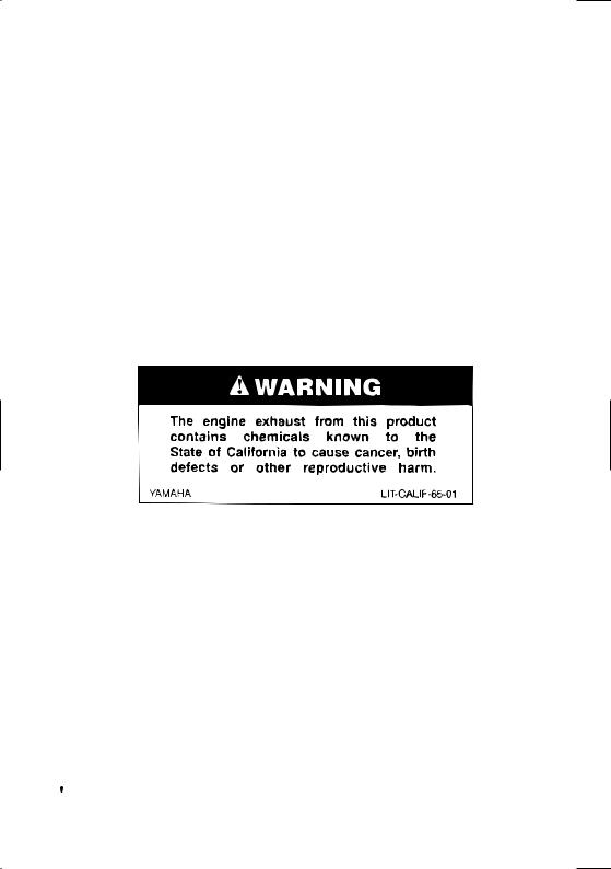
EXHAUST FUMES ARE POISONOUS
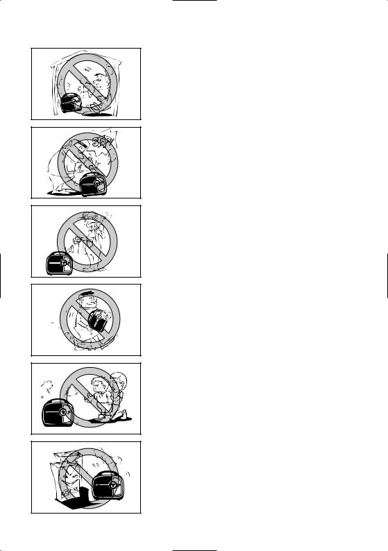
9Never operate the engine in a closed area or it may cause unconsciousness and death within a short time. Operate the engine in a well ventilated area.
AE00075
FUEL IS HIGHLY FLAMMABLE AND POISONOUS
9Always turn off the engine when refuelling.
9Never refuel while smoking or in the vicinity of an open flame.
9Take care not to spill any fuel on the engine or muffler when refueling.
9If you swallow any fuel, inhale fuel vapor, or allow any to get in your eye(s), see your doctor immediately. If any fuel spills on your skin or clothing, immediately wash with soap and water and change your clothes.
9When operating or transporting the machine, be sure it is kept upright. If it tilts, fuel may leak from the carburetor or fuel tank.
AE00843
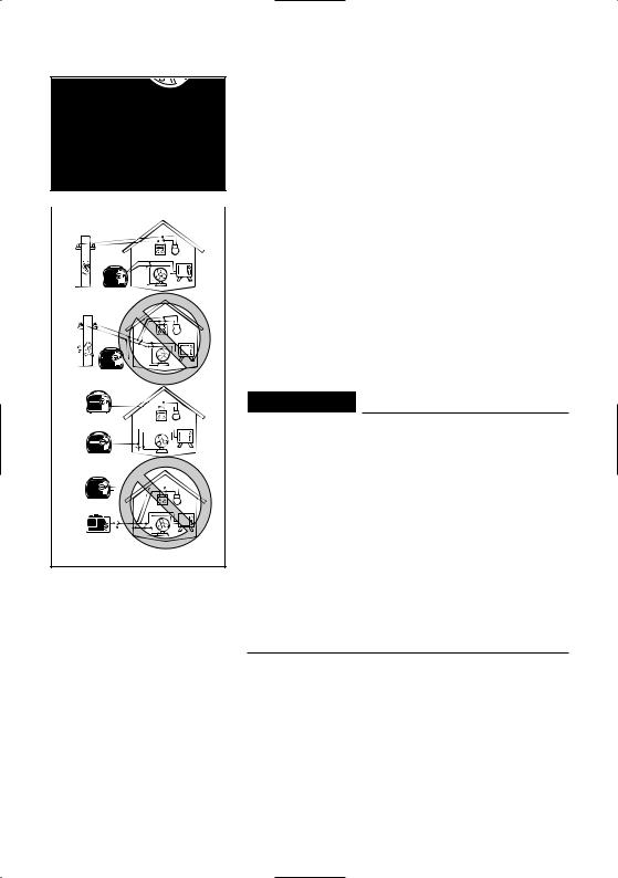
ENGINE AND MUFFLER MAY BE HOT
9Place the machine in a place where pedestrians or children are not likely to touch the machine.
9Avoid placing any flammable materials near the exhaust outlet during operation.
7DK-006
– 1 –
|
9 |
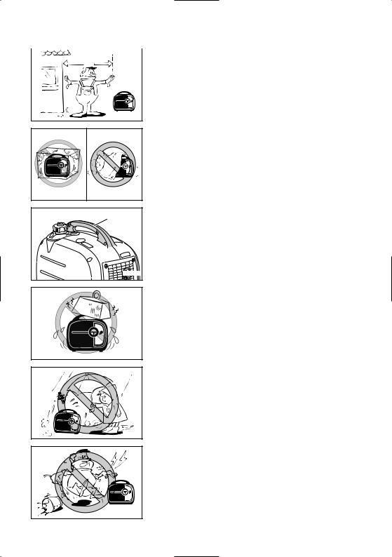
Keep the machine at least 1 m (3 ft) from buildings |
a |
or other equipment, or the engine may overheat. |
|
a 1 m (3 ft)
7DK-007
7DK-008a
1
7DK-036
9Do not operate the engine with a dust cover or other objects covering it.
9When covering the generator, be sure to do so only after the engine and muffler have completely cooled down.
9Be sure to carry the generator only by its carrying handles 1.
9 Do not place any obstacles on the generator.
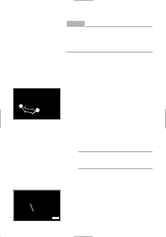
AE00083
ELECTRIC SHOCK PREVENTION
9 Never operate the engine in rain or snow.
7DK-009
9 Never touch the machine with wet hands or electrical shock will occur.
7DK-010
– 2 –
1 |
7DK-011 |
1 |
2
1
2
9Connect the ground lead of the machine to the ground (Earth) terminal 1 and connect the end to the ground electrode buried in the ground.
AE00088
CONNECTION NOTES
9Avoid connecting the generator to commercial power outlet.
9Avoid connecting the generator in parallel with any other generator.
1 Correct
2 Incorrect
AE00091
CONNECTION
 WARNING
Before the generator can be connected to a building’s electrical system, a licensed electrician must install an isolation (transfer) switch in the building’s main fuse box. The switch is the connection point for generator power and allows selection of generator or main line power to the building. This will prevent the generator from charging the main power line (backfeeding) when the main power supply has failed or has been turned off for line repair. Backfeeding can electrocute or injure line maintenance personnel. Also, generator and building electrical system damage can occur when normal operating power returns if unit is used without an isolation switch.
AE00086
EXTENSION CORD NOTES
Extension cords should be protected by a tough flexible rubber sheath (IEC 245) or the equivalent to withstand mechanical stresses.
– 3 –
AE00062
LOCATION OF IMPORTANT LABELS
Please read the following labels carefully before operating this machine.
TIP
Maintain or replace safety and instruction labels, as necessary.
1 |
2 |
3 |
4
6
7DK-013 |
5 |
7DK-014 |
1
 DANGER
Using a generator indoors CAN KILL YOU IN MINUTES.
Generator exhaust contains carbon monoxide.
This is a poison you cannot see or smell.
NEVER use inside a home or garage, EVEN IF doors and windows are open.
Only use OUTSIDE and far away from windows, door, and vents.
– 4 –
2
qWARNING
8Read the owner’s manual and all labels before operating.
8Only operate in well-ventilated areas. Exhaust gas contains poisonous carbon monoxide.
8Check for spilled fuel or fuel leaks.
8Stop engine before refueling.
8Do not operate near flammable materials.
8Electrocution can occur if generator is used in rain, snow, or near water. Keep this unit dry at all times.
8Electrocution or property damage can occur: Do not connect this generator to any building’s electrical system unless an isolation switch has been installed by a licensed electrician. Refer to the owner’s manual.
8When operating the generator:
Never place a partition or other barrier around the generator. |
|
Do not cover the generator with a box. |
7DK-24162-10 |
Do not place any objects on the generator. |
3
NOTICE
Use the specified spark plug only.
Specified plug:BPR6HS(NGK)
5
Important Emissions Information
YAMAHA MOTOR POWERED PRODUCTS CO.,LTD.
This engine meets **** California exhaust and evaporative emission regulations for small off-road engines.
This engine conforms to Phase 2 U.S.EPA regulations for small nonroad engines.
EMISSIONS COMPLIANCE PERIOD : CATEGORY A(EPA)
EF: ********* |
DISPLACEMENT: *** cc |
EVAP F: ******** |
EMISSION CONTROL SYSTEM: EM |
This engine is certified to operate on unleaded gasoline. |
|
ENGINE OIL: SAE10W-30 |
TYPE: SE |
No other adjustments needed.
4
HOT EXHAUST
7WL-28176-10
The air index of this engine is 3 (California only)
0 |
2 |
4 |
6 |
8 |
10 |
MOST CLEAN |
|
|
|
|
LEAST CLEAN |
Note: The lower the air index, the less the pollution. This engine is certified to be emissions compliant for the following use:
MODERATE |
INTERMEDIATE |
X |
EXTENDED |
(*** HOURS) |
(*** HOURS) |
(*** HOURS) |
Check owner's manual for further details.
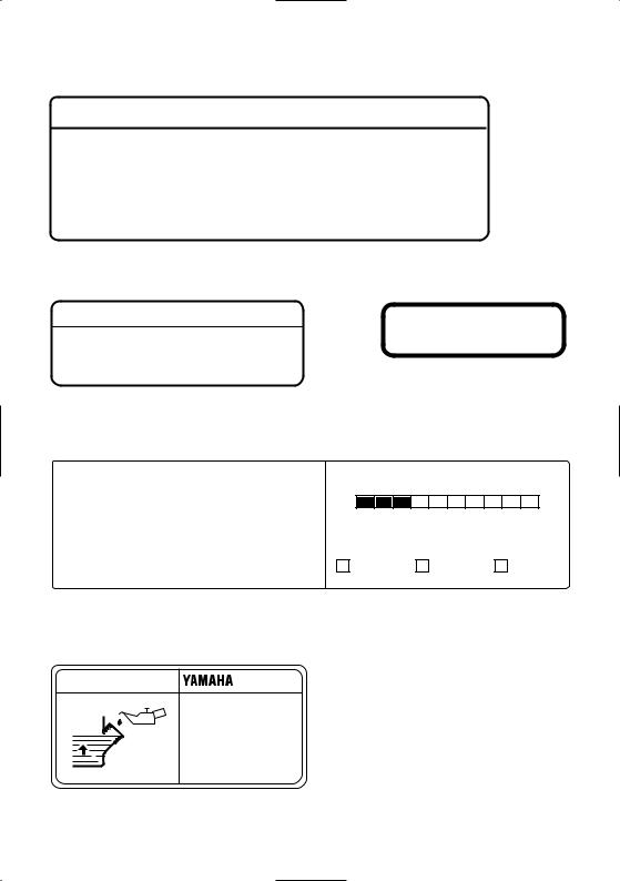
6
OIL |
|
EF2000IS |
|
AC output |
60Hz |
|
Rated |
1.6kVA |
|
Phase |
120V |
|
Single |
|
|
DC output |
12V 8A |
|
Fuel |
Gasoline |
|
YAMAHA MOTOR POWERED PRODUCTS CO.,LTD. |
|
7DK-24164-10 |
MADE IN JAPAN |
|
– 5 –

1 |
2 |
5 |
|
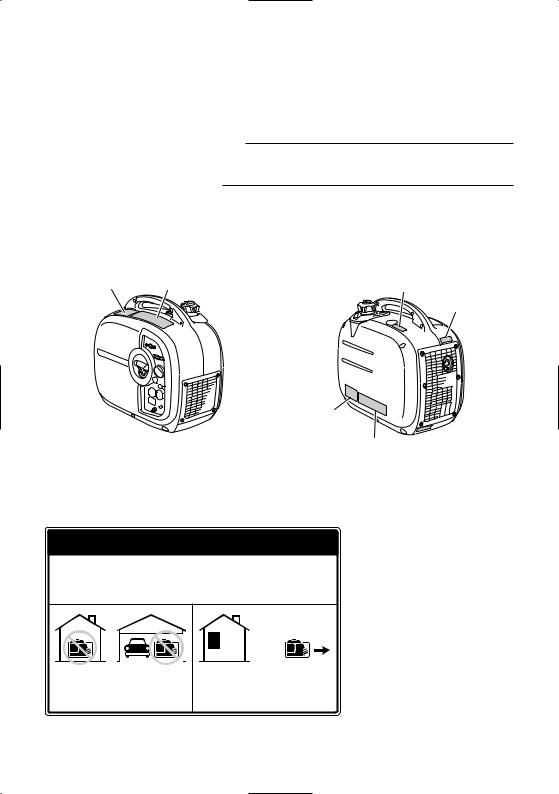
DESCRIPTION |
|
1 Carrying handle |
|||
|
3 |
|
|
|
|
|
|
2 Fuel tank cap air vent knob |
|
|
|
|
|
|
|
|
|
6 |
3 Fuel tank cap |
|
|
|
4 Recoil starter |
|
|
|
|
|
|
|
|
|
|
5 Fuel gauge |
|
|
|
|
6 Muffler |
|
|
|
|
7 Oil filler cap |
4 |
|
7 |
|
|
|
|
|
|
|
|
7DK-015 |
|
7DK-016 |
|
1 |
2 3 |
4 5 |
6
7
8
w
9
q |
0 |
7DK-017 |
|
|
AE00103
Control panel
1 Oil warning light
2 AC pilot light
3 Overload indicator light
4Economy control switch (Black)
5 Engine switch (Red)
6 Fuel cock knob
7 Choke knob
8Twin Tech (parallel running terminal)
9 AC receptacle
0 DC protector (breaker) q Ground (Earth) terminal w DC receptacle
– 6 –
|
|
AE00101 |
|
|
CONTROL FUNCTION |
|
|
AE00121 |
|
|
Engine switch |
2 |
|
The engine switch controls the ignition system. |
|
1 |
|
|
7DK-018 |
1 7 “ON” |
|
|
Ignition circuit is switched on.
The engine can be started.
2 5 “STOP”
Ignition circuit is switched off. The engine will not run.
AE00111
Oil warning light (Red)
When the oil level falls below the lower level, the oil warning light comes on and then the engine stops automatically. Unless you refill with oil, the engine will not start again.
TIP
If the engine stalls or does not start, turn the engine switch to “ON” and then pull the recoil starter. If the oil warning light flickers for a few seconds, the engine oil is insufficient. Add oil and restart.
700-115
DC protector
The DC protector turns off 2 automatically when electric device being connected to the generator is operating and current above the rated flows. To use this equipment again, turn on the DC protector by pressing its button to “ON” 1.
1 “ON”
Direct current is output. (This is the default position.)
2 “OFF”
Direct current is not output.
2 |
1 |
|
7DK-052 |
– 7 –
NOTICE
Reduce the load of the connected electric device below the specified rated output of the generator if the DC protector turns off. If the DC protector turns off again, stop using the device immediately and consult a Yamaha dealer.
2

 1
1
7DK-020
1
7DK-048
AE00142
Economy control switch
1 I “ON”
When the economy control switch is turned to “ON” 1, the economy control unit controls the engine speed according to the connected load. The results are better fuel consumption and less noise.
2 3 “OFF”
When the economy control switch is turned to “OFF” 2, the engine runs at the rated r/min (4,500 r/min) regardless of whether is a load connected or not.
TIP
The economy control switch must be turned to “OFF” 2 when using electric devices that require a large starting current, such as a compressor of a submergible pump.
AC pilot light (Green)
The AC pilot light 1 comes on when the engine starts and produces power.
– 8 –
 1
1
7DK-021
7DK-022
AE01087
Overload indicator light (Red)
The overload indicator light 1 comes on when an overload of a connected electrical device is detected, the inverter control unit overheats, or the AC output voltage rises. Then, the AC protector will trip, stopping power generation in order to protect the generator and any connected electric devices. The AC pilot light (Green) will go off and the overload indicator light (Red) will stay on, but the engine will not stop running.
When the overload indicator light comes on and power generation stops, proceed as follows:
1.Turn off any connected electric devices and stop the engine.
2.Reduce the total wattage of connected electric devices within the rated output.
3.Check for blockages in the cooling air inlet and around the control unit. If any blockages are found, remove.
4.After checking, restart the engine.
TIP
The overload indicator light may come on for a few seconds at first when using electric devices that require a large starting current, such as a compressor or a submergible pump. However, this is not a malfunction.
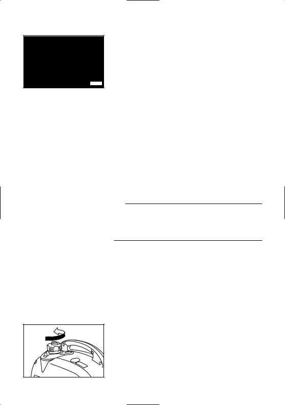
Fuel tank cap
Remove the fuel tank cap by turning it counterclockwise.
– 9 –
2
1
7DK-023
 2
2

1
7DK-024
1


7DK-011
7DK-042a
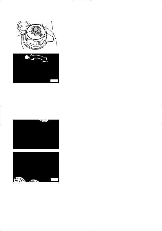
Fuel tank cap air vent knob
The fuel tank cap 2 is provided with an air vent knob 1 to stop fuel flow.
The air vent knob must be turned to “ON”. This will allow fuel to flow to the carburetor and the engine to run. When the engine is not in use, turn the air vent knob to “OFF” to stop fuel flow.
Fuel cock knob
The fuel cock supplies fuel from the fuel tank to the carburetor.
The fuel cock has two positions.
1 “ON”
With the knob in this position, fuel flows to the carburetor. Normal using is done with the knob in this position.
2 “OFF”
With the knob in this position, fuel will not flow. Always turn the knob to this position when the engine is not running.
Ground (Earth) terminal
Ground (Earth) terminal 1 connects the earth line for prevention of electric shock.
When the electric device is earthed, always the generator must be earthed.
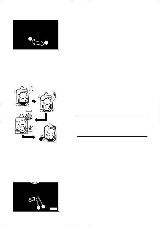
Twin Tech
(Terminal for Connecting special cables for parallel running)
This is the terminal for connecting special cables for parallel running of two EF2000iS. The parallel running requires two EF2000iS and the special cables. (The rated output in parallel running is 3.0 kVA and the rated current is 25.0 A.)
The handling, operation procedure and the notes on usage are described in the PARALLEL RUNNING KIT OWNER’S MANUAL included in the Parallel Running Kit. Consult a Yamaha dealer for this Parallel Running Kit.
– 10 –
 Loading...