


 Loading...
WaveRunner
GP1300R
SERVICE MANUAL
*LIT186160244*
LIT-18616-02-44 |
F1G-28197-1F-11 |

E 
NOTICE
This manual has been prepared by Yamaha primarily for use by Yamaha dealers and their trained mechanics when performing maintenance procedures and repairs to Yamaha equipment. It has been written to suit the needs of persons who have a basic understanding of the mechanical and electrical concepts and procedures inherent in the work, for without such knowledge attempted repairs or service to the equipment could render it unsafe or unfit for use.
Because Yamaha has a policy of continuously improving its products, models may differ in detail from the descriptions and illustrations given in this publication. Use only the latest edition of this manual. Authorized Yamaha dealers are notified periodically of modifications and significant changes in specifications and procedures, and these are incorporated in successive editions of this manual.
A10001-0*
WaveRunner GP1300R
SERVICE MANUAL
©2003 by Yamaha Motor Corporation, USA 1st Edition, February 2003
All rights reserved.
Any reprinting or unauthorized use without the written permission of Yamaha Motor Corporation, USA is expressly prohibited.
Printed in USA
LIT-18616-02-44

E 
HOW TO USE THIS MANUAL
MANUAL FORMAT
All of the procedures in this manual are organized in a sequential, step-by-step format. The information has been compiled to provide the mechanic with an easy to read, handy reference that contains comprehensive explanations of all disassembly, repair, assembly, and inspection operations.
In this revised format, the condition of a faulty component will precede an arrow symbol and the course of action required will follow the symbol, e.g.,
• Bearings
Pitting/scratches → Replace.
To assist you in finding your way through this manual, the section title and major heading is given at the top of every page.
ILLUSTRATIONS
The illustrations within this service manual represent all of the designated models.
CROSS REFERENCES
The cross references have been kept to a minimum. Cross references will direct you to the appropriate section or chapter.

E 
IMPORTANT INFORMATION
In this Service Manual particularly important information is distinguished in the following ways.
The Safety Alert Symbol means ATTENTION! BECOME ALERT! YOUR SAFETY IS INVOLVED!

 WARNING
Failure to follow WARNING instructions could result in severe injury or death to the machine operator, passenger(s), a bystander, or a person inspecting or repairing the watercraft.
CAUTION:
A CAUTION indicates special precautions that must be taken to avoid damage to the watercraft.
NOTE:
A NOTE provides key information to make procedures easier or clearer.
IMPORTANT:
This part has been subjected to change of specification during production.

E 
HOW TO USE THIS MANUAL
1To help identify parts and clarify procedure steps, there are exploded diagrams at the start of each removal and disassembly section.
2Numbers are given in the order of the jobs in the exploded diagram.
3Symbols indicate parts to be lubricated or replaced (see “SYMBOLS”).
4A job instruction chart accompanies the exploded diagram, providing the order of jobs, names of parts, notes in jobs, etc.
5Dimension figures and the number of parts, are provided for fasteners that require a tightening torque.
Example: |
|
Bolt or screw size |
10 × 25 mm : M10 (D) × 25 mm (L) |
D
L
6Jobs requiring more information (such as special service tools and technical data) are described sequentially.
E 
1 |
2 |
|
|||
|
|
|
|
|
|
|
GEN |
|
|
SPEC |
|
|
INFO |
|
|
|
|
|
|
|
|
|
|
3 4
INSP  FUEL
FUEL
ADJ
5 |
6 |
POWR |
JET |
|
PUMP |
||
|
||
7 |
8 |
|
ELEC – + |
HULL |
|
|
HOOD |
|
9 |
0 |
|
TRBL |
|
|
ANLS |
|
|
A |
B |
C D
T .
R .
E F
E |
G H
A |
M |
I J
GM |
4 |
K L
LT |
LT |
271 |
242 |
M N
LT
SS
572
A50001-1-4
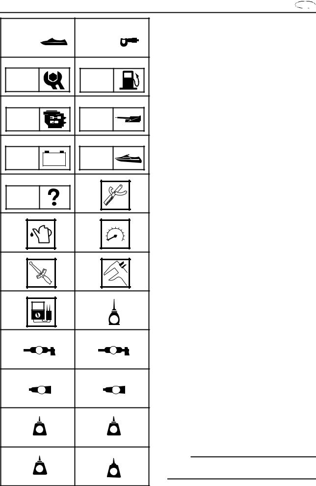
SYMBOLS
Symbols 1 to 9 are designed to indicate the content of a chapter.
1General Information
2Specifications
3Periodic Inspection and Adjustment
4Fuel System
5Power Unit
6Jet Pump Unit
7Electrical System
8Hull and Hood
9Trouble Analysis
Symbols 0 to E indicate specific data.
0 Special service tool
ASpecified oil or fluid
BSpecified engine speed
CSpecified tightening torque
DSpecified measurement
ESpecified electrical value (resistance, voltage, electric current)
Symbols F to H in an exploded diagram indicate the grade of lubricant and the lubrication point.
FApply Yamaha 2-stroke motor oil
GApply water resistant grease
(Yamaha grease A, Yamaha marine grease)
HApply molybdenum disulfide grease
Symbols I to N in an exploded diagram indicate the type of sealant or locking agent and the application point.
IApply Gasket Maker
JApply Yamabond No. 4
KApply LOCTITE 271 (red)
LApply LOCTITE 242 (blue)
MApply LOCTITE 572
NApply silicone sealant
NOTE:
Additional symbols may be used in this manual.

E 
A30000-0 |
INDEX |
|
|
|
|
|
|
|
|
|
|
|
|
|
|
|
|
|
|
|
|
|
|
|
|
||
|
|
|
|
|
|
|
|
|
|
|
|
||
GENERAL INFORMATION |
|
|
|
|
|
|
|
|
|
|
1 |
||
|
GEN |
||||||||||||
|
|
INFO |
|||||||||||
|
|
|
|
|
|
|
|
|
|
|
|
|
|
SPECIFICATIONS |
|
|
|
|
|
|
|
|
|
|
2 |
||
SPEC |
|||||||||||||
|
|
||||||||||||
|
|
|
|
|
|
|
|
|
|
|
|
||
|
|
|
|
|
|
|
|
|
|
|
|
|
|
PERIODIC INSPECTION AND |
|
|
|
|
|
|
|
|
|
|
3 |
||
ADJUSTMENT |
|
ADJ |
|||||||||||
|
|
INSP |
|
||||||||||
|
|
|
|
|
|
|
|
|
|
|
|
|
|
FUEL SYSTEM |
|
|
|
|
|
|
|
|
|
|
4 |
||
|
|
|
|
|
|
|
|
|
|
||||
FUEL |
|||||||||||||
|
|
||||||||||||
|
|
|
|
|
|
|
|
|
|
|
|
|
|
|
|
|
|
|
|
|
|
|
|
|
|
|
|
POWER UNIT |
|
|
|
|
|
|
|
|
|
|
|
5 |
|
|
|
|
|
|
|
|
|
|
|
|
|||
|
|
|
|
|
|
|
|
|
|
|
|||
|
POWR |
||||||||||||
|
|
||||||||||||
|
|
|
|
|
|
|
|
|
|
|
|
||
|
|
|
|
|
|
|
|
|
|
|
|
|
|
JET PUMP UNIT |
|
|
|
|
|
|
|
|
|
|
6 |
||
|
JET |
||||||||||||
|
|
PUMP |
|||||||||||
|
|
|
|
|
|
|
|
|
|
|
|
|
|
|
|
|
|
|
|
|
|
|
|
|
7 |
||
|
|
|
– + |
|
|
||||||||
ELECTRICAL SYSTEM |
|
|
|
|
|
|
|
|
|
|
|||
|
|
|
|
|
|
|
|
|
|
||||
ELEC |
|||||||||||||
|
|
||||||||||||
|
|
|
|
|
|
|
|
|
|
|
|
||
|
|
|
|
|
|
|
|
|
|
|
|
|
|
HULL AND HOOD |
|
|
|
|
|
|
|
|
|
|
8 |
||
HULL |
|||||||||||||
|
|
HOOD |
|||||||||||
|
|
|
|
|
|
|
|
|
|
|
|
|
|
TROUBLE ANALYSIS |
|
|
|
|
|
|
|
|
|
|
9 |
||
TRBL |
|||||||||||||
|
|
ANLS |
|||||||||||
GEN |
|
|
|
|
INFO |
|
|
E |
|
|
|
|
CHAPTER 1 |
|
|
|
|
GENERAL INFORMATION |
|
IDENTIFICATION NUMBERS ......................................................................... |
1-1 |
|||
|
PRIMARY l.D. NUMBER ........................................................................... |
1-1 |
||
|
ENGINE SERIAL NUMBER ...................................................................... |
1-1 |
||
|
JET PUMP UNIT SERIAL NUMBER ......................................................... |
1-1 |
||
|
HULL IDENTIFICATION NUMBER (H.l.N.)............................................... |
1-1 |
||
|
SAFETY WHILE WORKING...................................................................... |
1-2 |
||
|
FIRE PREVENTION .................................................................................. |
1-2 |
||
|
VENTILATION ........................................................................................... |
1-2 |
||
|
SELF-PROTECTION................................................................................. |
1-2 |
||
|
PARTS, LUBRICANTS, AND SEALANTS ................................................ |
1-2 |
||
|
GOOD WORKING PRACTICES ............................................................... |
1-3 |
||
|
DISASSEMBLY AND ASSEMBLY ............................................................ |
1-4 |
||
SPECIAL SERVICE TOOLS ........................................................................... |
1-5 |
|||
|
MEASURING AND DIAGNOSIS ............................................................... |
1-5 |
||
|
REMOVAL AND INSTALLATION.............................................................. |
1-7 |
||
1
2
3
4
5
6
7
8
9
GEN INFO
IDENTIFICATION NUMBERS
E 
|
A60700-0* |
|
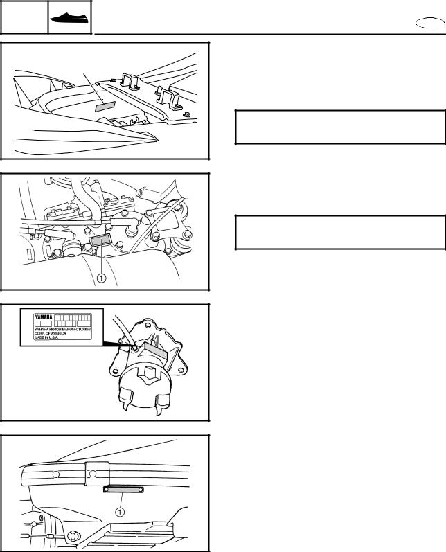
IDENTIFICATION NUMBERS |
1 |
PRIMARY l.D. NUMBER |
|
The primary l.D. number is stamped on a label |
|
1 attached inside the engine compartment. |
|
Starting primary l.D. number: |
|
F1G: 800301 |
ENGINE SERIAL NUMBER
The engine serial number is stamped on a label 1 attached to the engine unit.
Starting serial number: 60T: 1000001
JET PUMP UNIT SERIAL NUMBER
The jet pump unit serial number is stamped on a label attached to the intermediate housing.
HULL IDENTIFICATION NUMBER (H.l.N.)
The H.l.N. is stamped on a plate 1 attached to the hull on the aft, starboard (right) side.
1-1
GEN INFO
SAFETY WHILE WORKING |
E |
 SAFETY WHILE WORKING
To prevent and accident or injury and to ensure quality service, follow the safety procedures provided below.
FIRE PREVENTION
Gasoline is highly flammable.
Keep gasoline and all flammable products away from heat, sparks, and open flames.
VENTILATION
Gasoline vapor and exhaust gas are heavier than air and extremely poisonous. If inhaled in large quantities they may cause loss of consciousness and death within a short time. When test running an engine indoors (e.g., in a water tank), be sure to do so where adequate ventilation can be maintained.
SELF-PROTECTION
Protect your eyes by wearing safety glasses or safety goggles during all operation involving drilling and grinding, or when using an air compressor.
Protect your hands and feet by wearing protective gloves or safety shoes when necessary.
PARTS, LUBRICANTS, AND SEALANTS
Use only genuine Yamaha parts, lubricants, and sealants or those recommended by Yamaha, when servicing or repairing the watercraft.
1-2
GEN INFO
SAFETY WHILE WORKING |
E |
Under normal conditions, the lubricants mentioned in this manual should not harm or be hazardous to your skin. However, you should follow these precautions to minimize any risk when working with lubricants.
1.Maintain good standards of personal and industrial hygiene.
2.Change and wash clothing as soon as possible if soiled with lubricants.
3.Avoid contact with skin. Do not, for example, place a soiled rag in your pocket.
4.Wash hands and any other part of the body thoroughly with soap and hot water after contact with a lubricant or lubricant soiled clothing has been made.
5.To protect your skin, apply a protective cream to your hands before working on the watercraft.
6.Keep a supply of clean, lint-free cloths for wiping up spills, etc.
GOOD WORKING PRACTICES
1.The right tools
Use the recommended special service tools to protect parts from damage. Use the right tool in the right manner—do not improvise.
2.Tightening torques
Follow the tightening torque specifications provided throughout the manual. When tightening nuts, bolts, and screws, tighten the large sizes first, and tighten fasteners starting in the center and moving outward.
1-3
GEN INFO
SAFETY WHILE WORKING |
E |
3.Non-reusable parts
Always use new gaskets, seals, O-rings, oil seals, cotter pins, circlips, etc., when installing or assembling parts.
DISASSEMBLY AND ASSEMBLY
1.Use compressed air to remove dust and dirt during disassembly.
2.Apply engine oil to the contact surfaces of moving parts during assembly.
3.Install bearings with the manufacture identification mark in the direction indication in the installation procedure. In addition, be sure to lubricate the bearings liberally.
4.Apply a thin coat of water-resistant grease to the lip and periphery of an oil seal before installation.
5.Check that moving parts operate normally after assembly.
1-4
GEN INFO
SPECIAL SERVICE TOOLS |
E |
|
|
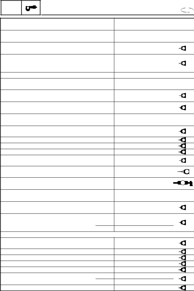
SPECIAL SERVICE TOOLS
1 YU-34899-A |
2 90890-03174 |
3 YU-03097 |
90890-01252 |
4 YU-03112 |
5 YW-06842 |
90890-03112 |
90890-06842 |
6 YB-06766 |
90890-06786 |
7 YU-03017
90890-06759
Using the special service tools recommended by Yamaha will aid service and enable accurate assembly and tune-up. Improvisations and using improper tools can damage the equipment.
NOTE:
•For USA and Canada, use the special service tools starting with part numbers “J-,” “YB-,” “YM-,” “YS-,” “YU-,” or “YW-.”
•For all other countries, use the special service tools starting with part number “90890-.”
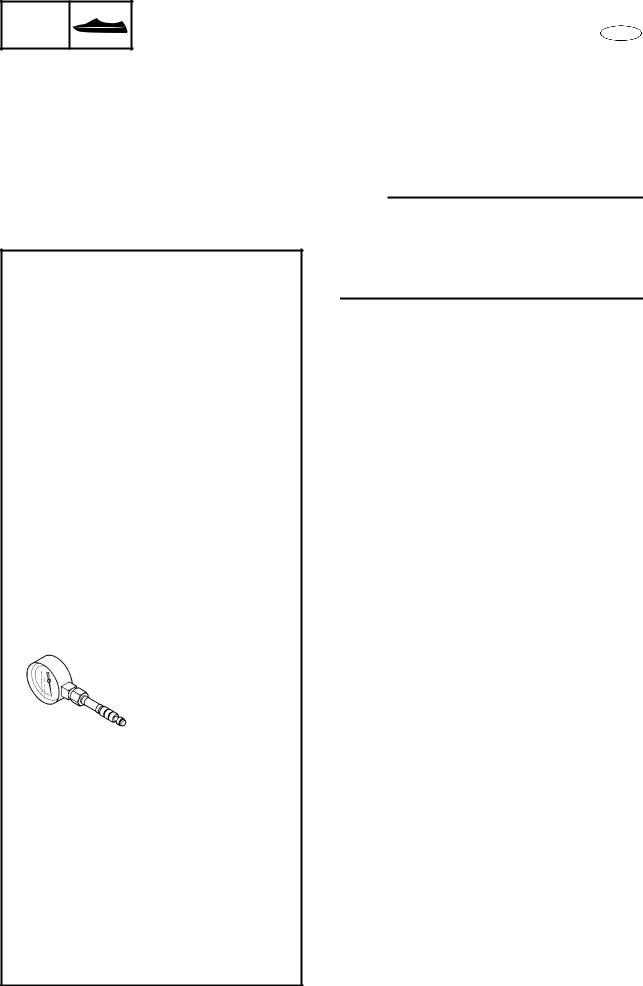
MEASURING AND DIAGNOSIS
1Digital multimeter YU-34899-A
2Digital circuit tester 90890-03174
3Dial gauge YU-03097 90890-01252
4Pocket tester YU-03112 90890-03112
5Fuel pressure gauge adapter YW-06842
90890-06842
6Fuel pressure gauge YB-06766 90890-06786
7Cylinder gauge set YU-03017 90890-06759
8Compression gauge YU-33223-1 90890-03160
8 YU-33223-1 |
90890-03160 |
1-5
GEN |
SPECIAL SERVICE TOOLS |
|
||||
INFO |
E |
|||||
|
|
|
|
9 |
Peak volt meter adapter |
|
9 YU-39991 |
0 90890-03172 |
|
YU-39991 |
|
||
|
|
|
|
0 |
Peak voltage adapter B |
|
|
|
|
|
|
90890-03172 |
|
|
|
|
|
A Spark gap tester |
|
|
|
|
|
|
|
YM-34487 |
|
|
|
|
|
B Ignition tester |
|
|
|
|
|
|
|
90890-06754 |
|
A YM-34487 |
B 90890-06754 |
C |
Lighting coil tester (3 pins) |
|
||
|
YB-06870 |
|
||||
|
|
|
|
|
|
|
|
|
|
|
|
Test harness SMT250-3 (3 pins) |
|
|
|
|
|
|
90890-06870 |
|
|
|
|
|
D Air pressure sensor tester (3 pins) |
|
|
|
|
|
|
|
YB-06869 |
|
|
|
|
|
|
Test harness EJ-II-3 (3 pins) |
|
C YB-06870 |
D YB-06869 |
|
90890-06869 |
|
||
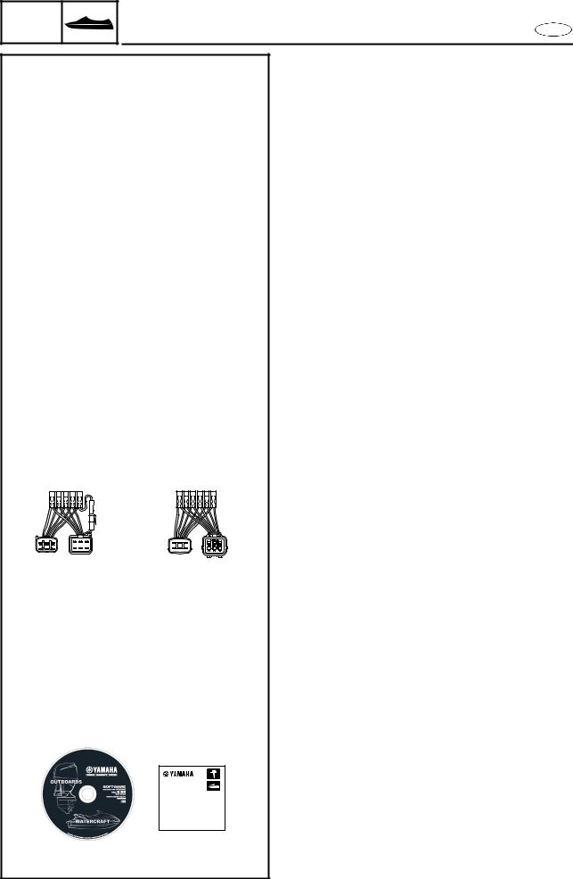
E Test harness (6 pins) |
|
|||||
|
90890-06870 |
|
90890-06869 |
|
||
|
|
|
|
|
YB-06848 |
|
|
|
|
|
|
Test harness FSW-6A (6 pins) |
|
|
|
|
|
|
90890-06848 |
|
|
|
|
|
F Test harness (6 pins) |
|
|
|
|
|
|
|
YB-06849 |
|
|
|
|
|
|
Test harness SM6195021-6 (6 pins) |
|
|
|
|
|
|
90890-06849 |
|
E |
YB-06848 |
F |
YB-06849 |
G Lower unit pressure/vacuum tester |
|
|
90890-06848 |
90890-06849 |
|
||||
|
|
|
YB-35956-A |
|
||
|
|
|
|
|
|
|
|
|
|
|
|
Vacuum/pressure pump gauge set |
|
|
|
|
|
|
90890-06756 |
|
|
|
|
|
H Yamaha diagnostic system |
|
|
|
|
|
|
|
(CD-ROM only) |
|
|
|
|
|
|
60V-WS853-01 |
|
G YB-35956-A |
|
|
|
|
|
|
|
90890-06756 |
|
|
|
|
|
H 60V-WS853-01
YAMAHA
DIAGNOSTIC
SYSTEM
INSTALLATION MANUAL
60V-2819K-10
1-6

GEN |
|
|
SPECIAL SERVICE TOOLS |
|
|||
INFO |
|
|
E |
||||
|
|
|
|
REMOVAL AND INSTALLATION |
|
||
|
|
|
|
|
|||
1 YW-06551 |
2 YW-06550 |
1 Coupler wrench |
|
||||
|
|
|
90890-06550 |
|
YW-06551 |
|
|
90890-06551 |
|
|
|||||
|
90890-06551 |
|
|||||
|
|
|
|
|
|
||
|
|
|
|
2 |
Flywheel holder |
|
|
|
|
|
|
|
YW-06550 |
|
|
|
|
|
|
|
90890-06550 |
|
|
|
|
|
|
3 |
Universal puller |
|
|
|
|
|
|
|
YB-06117 |
|
|
3 YB-06117 |
4 90890-06521 |
4 |
Flywheel puller |
|
|||
|
90890-06521 |
|
|||||
|
|
|
|
5 |
Drive shaft holder (impeller) |
|
|
|
|
|
|
|
YB-06151 |
|
|
|
|
|
|
|
Drive shaft holder 5 (impeller) |
|
|
|
|
|
|
|
90890-06519 |
|
|
|
|
|
|
6 |
Slide hammer and adapters |
|
|
|
|
|
|
|
(jet pump bearing) |
|
|
5 YB-06151 |
6 YB-06096 |
|
YB-06096 |
|
|||
7 Stopper guide plate (jet pump bearing) |
|||||||
90890-06519 |
|
|
|||||
|
|
|
|
|
90890-06501 |
|
|
|
|
|
|
8 |
Bearing puller assembly |
|
|
|
|
|
|
|
(jet pump bearing) |
|
|
|
|
|
|
|
90890-06535 |
|
|
|
|
|
|
9 |
Stopper guide stand (jet pump bearing) |
||
|
|
|
|
|
90890-06538 |
|
|
|
|
|
|
0 |
Driver rod L3 (jet pump bearing) |
|
|
7 90890-06501 |
|
8 90890-06535 |
|
90890-06652 |
|
||
|
|
|
|
A Bearing housing needle bearing remover |
|||
|
|
|
|
|
(jet pump bearing) |
|
|
|
|
|
|
|
YB-06112 |
|
|
|
|
|
|
|
Drive shaft needle bearing installer and |
||
|
|
|
|
|
remover (jet pump oil seal) |
|
|
|
|
|
|
|
YB-06196 |
|
|
|
|
|
|
B Needle bearing attachment |
|
||
9 90890-06538 |
|
0 90890-06652 |
|
(jet pump bearing and oil seal) |
|
||
|
|
|
|
|
90890-06614, 90890-06653 |
|
|
A YB-06112 |
B 90890-06614 |
YB-06196 |
90890-06653 |
1-7

GEN INFO
SPECIAL SERVICE TOOLS
E 
C YB-06085 |
D 90890-06634 |
E YB-06071 |
F 90890-06606 |
G YB-34474 H YB-06552
90890-06552
I YB-06156
90890-06626
COuter race installer—forward gear (jet pump oil seal)
YB-06085
DBall bearing attachment (jet pump oil seal) 90890-06634
EDriver handle—large (intermediate shaft and jet pump) YB-06071
FDriver rod LS
(intermediate shaft and jet pump) 90890-06606
GDrive shaft needle bearing depth stop (jet pump bearing)
YB-34474
HShaft holder (intermediate shaft) YB-06552
Crankshaft holder 20 (intermediate shaft) 90890-06552
IDrive shaft taper roller bearing cup installer (intermediate shaft) YB-06156
Bearing outer race attachment (intermediate shaft) 90890-06626
1-8

SPEC |
|
|
E |
|
|
|
|
|
|
|
|
|
CHAPTER 2 |
|
|
|
|
SPECIFICATIONS |
|
GENERAL SPECIFICATIONS ....................................................................... |
2-1 |
|||
MAINTENANCE SPECIFICATIONS ............................................................... |
2-3 |
|||
|
ENGINE .................................................................................................... |
2-3 |
||
|
JET PUMP UNIT ...................................................................................... |
2-4 |
||
|
HULL AND HOOD .................................................................................... |
2-5 |
||
|
ELECTRICAL ............................................................................................ |
2-5 |
||
TIGHTENING TORQUES ................................................................................ |
2-8 |
|||
|
SPECIFIED TORQUES............................................................................. |
2-8 |
||
|
GENERAL TORQUE ............................................................................... |
2-14 |
||
CABLE AND HOSE ROUTING ..................................................................... |
2-15 |
|||
1
2
3
4
5
6
7
8
9

SPEC
GENERAL SPECIFICATIONS
E 
GENERAL SPECIFICATIONS
Item |
Unit |
Model |
|
|
|||
GP1300R |
|||
|
|
||
|
|
|
|
Model code |
|
|
|
Hull |
|
F1G |
|
Engine/jet |
|
60T |
|
|
|
|
|
Dimensions |
|
|
|
Length |
mm (in) |
2,930 (115.4) |
|
Width |
mm (in) |
1,150 (45.3) |
|
Height |
mm (in) |
1,020 (40.2) |
|
Dry weight |
kg (lb) |
297 (653) |
|
Maximum capacity |
Person/kg (lb) |
2/160 (353) |
|
|
|
|
|
Performance |
|
|
|
Maximum output |
kW (PS) at r/min |
121.4 (165) at 7,000 |
|
Maximum fuel consumption |
l/h (US gal/h, |
63.0 (16.6, 13.9) |
|
|
lmp gal/h) |
|
|
Cruising range |
h |
0.95 |
|
|
|
|
|
Engine |
|
|
|
Engine type |
|
2-stroke |
|
Number of cylinders |
|
3 |
|
Displacement |
cm3 (cu. in) |
1,297 (79.1) |
|
Bore × stroke |
mm (in) |
84 × 78 (3.31 × 3.07) |
|
Compression ratio |
|
|
|
#1, #2 |
|
5.9:1 |
|
#3 |
|
5.7:1 |
|
Intake system |
|
Reed valve |
|
Scavenging system |
|
Loop charge |
|
Exhaust system |
|
Wet exhaust/YPVS |
|
Lubrication system |
|
Variable oil injection |
|
Cooling system |
|
Water cooled |
|
Starting system |
|
Electric starter |
|
Ignition system |
|
Digital CDI |
|
Spark plug model |
|
BR8ES-11 (NGK) |
|
(manufacturer) |
|
|
|
Spark plug gap |
mm (in) |
1.0–1.1 (0.039–0.043) |
|
Battery |
|
|
|
Voltage, capacity |
V, Ah |
12, 19 |
|
Generator output |
A at r/min |
15 at 6,000 |
|
|
|
|
2-1

SPEC
GENERAL SPECIFICATIONS
E 
|
Item |
Unit |
Model |
|
|
||
|
GP1300R |
||
|
|
|
|
|
|
|
|
Drive unit |
|
|
|
|
Propulsion system |
|
Jet pump |
|
Jet pump type |
|
Axial flow, single stage |
|
Impeller rotation |
|
Counterclockwise (viewed from rear) |
|
Transmission |
|
Direct drive from engine |
|
Jet thrust nozzle horizontal |
Degree |
23 + 23 |
|
angle |
|
|
|
Jet thrust nozzle trim angle |
Degree |
–5, 0, 5, 10, 15 |
|
Trim system |
|
Manual 5 positions |
|
Reverse system |
|
NA |
|
|
|
|
Fuel and oil |
|
|
|
|
Fuel |
|
Regular unleaded gasoline |
|
Minimum fuel rating |
PON*1 |
86 |
|
|
RON*2 |
90 |
|
Oil |
|
YAMALUBE 2-W*3 |
|
Fuel-oil ratio |
|
30:1 |
|
(wide open throttle) |
|
|
|
Fuel tank capacity |
L (US gal, |
60 (15.9, 13.2) |
|
|
Imp gal) |
|
|
Oil tank quantity |
L (US qt, |
5.5 (1.5, 1.2) |
|
|
Imp qt) |
|
|
|
|
|
*1 |
Pump Octane Number = (Motor Octane Number + Research Octane Number)/2 |
||
*2 |
Research Octane Number |
|
|
*3 |
YAMALUBE 2-W has been developed for this watercraft and it is available at a Yamaha dealer. |
||
CAUTION:
Use only YAMALUBE 2-W oil. Using another oil can seriously damage the catalytic converter and other engine components.
2-2

SPEC
MAINTENANCE SPECIFICATIONS
E 
MAINTENANCE SPECIFICATIONS
ENGINE
Item |
Unit |
Model |
|
|
|||
GP1300R |
|||
|
|
||
|
|
|
|
Cylinder head |
|
|
|
Warpage limit |
mm (in) |
0.05 (0.002) |
|
Minimum compression |
kPa |
640 (6.4, 91) |
|
pressure*1 |
(kgf/cm2, psi) |
|
|
Cylinders |
|
|
|
Bore size |
mm (in) |
84.000–84.018 (3.3071–3.3078) |
|
Taper limit |
mm (in) |
0.080 (0.0031) |
|
Out-of-round limit |
mm (in) |
0.050 (0.0020) |
|
Wear limit |
mm (in) |
84.100 (3.3110) |
|
|
|
|
|
Pistons |
|
|
|
Piston diameter |
mm (in) |
Red: 83.899–83.902 (3.3031–3.3032) |
|
|
|
Orange: 83.903–83.906 (3.3033–3.3034) |
|
|
|
Green: 83.907–83.910 (3.3034–3.3035) |
|
|
|
Purple: 83.911–83.914 (3.3036–3.3037) |
|
Measuring point* |
mm (in) |
11 (0.43) |
|
Piston-to-cylinder clearance |
mm (in) |
0.100–0.105 (0.0039–0.0041) |
|
Wear limit |
mm (in) |
0.155 (0.0061) |
|
Piston pin boss inside diameter |
mm (in) |
22.008–22.020 (0.8665–0.8669) |
|
|
|
|
|
Piston rings |
|
|
|
Top |
|
|
|
Type |
|
Keystone |
|
Dimension (B) |
mm (in) |
1.47–1.49 (0.058–0.059) |
|
Dimension (T) |
mm (in) |
3.0–3.2 (0.118–0.126) |
|
End gap |
mm (in) |
0.45–0.60 (0.018–0.024) |
|
Ring groove clearance |
mm (in) |
0.020–0.070 (0.0008–0.0028) |
|
2nd |
|
|
|
Type |
|
Keystone |
|
Dimension (B) |
mm (in) |
1.47–1.49 (0.058–0.059) |
|
Dimension (T) |
mm (in) |
3.0–3.2 (0.118–0.126) |
|
End gap |
mm (in) |
0.45–0.60 (0.018–0.024) |
|
Ring groove clearance |
mm (in) |
0.020–0.070 (0.0008–0.0028) |
|
|
|
|
|
Piston pins |
|
|
|
Outside diameter |
mm (in) |
21.995–22.000 (0.8659–0.8661) |
|
Wear limit |
mm (in) |
21.990 (0.8657) |
|
|
|
|
|
Connecting rod |
|
|
|
Small end inside diameter |
mm (in) |
26.995–27.008 (1.0628–1.0633) |
|
|
|
|
*1Measuring conditions:
Engine temperature 48 °C (118 °F), wide open throttle, with spark plugs removed from all cylinders.
The figures are for reference only.
2-3
SPEC
MAINTENANCE SPECIFICATIONS
E 
Item |
Unit |
Model |
|
|
|||
GP1300R |
|||
|
|
||
|
|
|
|
Crankshaft assembly |
|
|
|
Crank width A |
mm (in) |
72.95–73.00 (2.872–2.874) |
|
Deflection limit B |
mm (in) |
0.05 (0.002) |
|
Deflection limit C |
mm (in) |
0.15 (0.006) |
|
Big end side clearance D |
mm (in) |
0.250–0.750 (0.0098–0.0295) |
|
Maximum small end axial |
mm (in) |
2.000 (0.0787) |
|
play E |
|
|
|
|
|
|
|
Throttle body |
|
|
|
Model/quantity |
|
60TA/3 |
|
Manufacturer |
|
SANSHIN |
|
ID mark |
|
60T00 |
|
Trolling speed |
r/min |
1,250–1,450 |
|
|
|
|
|
Reed valves |
|
|
|
Thickness |
mm (in) |
0.6 (0.024) |
|
Reed valve stopper height |
mm (in) |
10.5–10.9 (0.413–0.429) |
|
Reed valve warpage limit |
mm (in) |
1.5 (0.059) |
|
|
|
|
|
Fuel pump |
|
|
|
Pump type |
|
Electrical |
|
Output pressure |
kPa |
320.8–327.2 (3.21–3.27, 45.62–46.53) |
|
|
(kgf/cm2, psi) |
|
|
Coupling clearance |
|
|
|
Vertical |
mm (in) |
0–0.5 (0–0.020) |
|
Horizontal |
mm (in) |
2–4 (0.079–0.157) |
|
|
|
|
|
JET PUMP UNIT |
|
|
|
|
|
|
|
Item |
Unit |
Model |
|
|
|||
GP1300R |
|||
|
|
||
|
|
|
|
Jet pump |
|
|
|
Impeller material |
|
Stainless steel |
|
Number of impeller blades |
|
4 |
|
Impeller pitch angle |
Degree |
16.3 |
|
Impeller clearance |
mm (in) |
0.7–0.9 (0.028–0.035) |
|
Impeller clearance limit |
mm (in) |
0.9 (0.035) |
|
Drive shaft runout limit |
mm (in) |
0.30 (0.0118) |
|
Nozzle diameter |
mm (in) |
85.0–85.6 (3.35–3.37) |
|
|
|
|
2-4

SPEC |
|
|
MAINTENANCE SPECIFICATIONS |
|
|
|
|
HULL AND HOOD |
|
||
E 
Item |
Unit |
Model |
|
|
|||
GP1300R |
|||
|
|
||
|
|
|
|
Free play |
|
|
|
YPVS cable slack |
mm (in) |
0.5–1.5 (0.02–0.06) |
|
Throttle lever free play |
mm (in) |
4–7 (0.16–0.28) |
|
|
|
|
ELECTRICAL
Item |
Unit |
Model |
||
|
||||
GP1300R |
||||
|
|
|
||
|
|
|
|
|
Battery |
|
|
|
|
Type |
|
|
Fluid |
|
Voltage, capacity |
V, Ah |
12, 19 |
||
Specific gravity |
|
1.28 |
||
|
|
|
|
|
ECM unit |
|
|
|
|
(B/R – Ground for cylinder #1) |
|
|
||
(B/W – Ground for cylinder #2) |
|
|
||
(B/Y – Ground for cylinder #3) |
|
|
||
Output peak voltage lower |
|
|
||
limit |
|
|
|
|
|
at cranking |
V |
0.8 |
|
|
at 2,000 r/min |
V |
174 |
|
|
at 3,500 r/min |
V |
156 |
|
|
|
|
|
|
Stator |
|
|
|
|
Pickup coil |
|
|
|
|
(W/R, W/B, W/Y – B) |
|
|
||
Output peak voltage |
|
|
||
|
at cranking 1 |
V |
6.0 |
|
|
at cranking 2 |
V |
6.0 |
|
|
at 2,000 r/min |
V |
24 |
|
|
at 3,500 r/min |
V |
40 |
|
Pickup coil resistance 1 |
Ω |
459–561 |
||
|
(W/R – B) |
|
|
|
Pickup coil resistance 2 |
Ω |
459–561 |
||
|
(W/B – B) |
|
|
|
Pickup coil resistance 3 |
Ω |
459–561 |
||
|
(W/Y – B) |
|
|
|
Lighting coil |
(G – G) |
|
|
|
Output peak voltage |
|
|
||
|
at cranking 1 |
V |
9.0 |
|
|
at cranking 2 |
V |
7.5 |
|
|
at 2,000 r/min |
V |
12.5 |
|
|
at 3,500 r/min |
V |
12.5 |
|
Lighting coil resistance |
Ω |
0.54–0.66 |
||
|
(G – G) |
|
|
|
Cranking 1: unloaded |
|
|
||
Cranking 2: loaded |
|
|
||
2-5

SPEC
MAINTENANCE SPECIFICATIONS
E 
Item |
|
Unit |
Model |
|
|
|
|||
|
GP1300R |
|||
|
|
|
|
|
|
|
|
|
|
Ignition coil |
|
|
|
|
Minimum spark gap |
|
mm (in) |
10–11 (0.39–0.43) |
|
Primary coil resistance |
Ω |
0.26–0.36 |
||
|
(B/W – body) |
|
|
|
Secondary coil resistance |
kΩ |
3.5–4.7 |
||
(B/W – spark plug lead |
|
|
||
|
terminal) |
|
|
|
Spark plug lead resistance |
|
|
||
|
|
#1 |
kΩ |
6.1–14.3 |
|
|
#2 |
kΩ |
4.5–10.9 |
|
|
#3 |
kΩ |
3.3–8.2 |
|
|
|
|
|
Rectifier/regulator |
(R – B) |
|
|
|
Output peak voltage |
|
|
|
|
(unloaded) |
|
|
|
|
|
at 3,500 r/min |
V |
14.5 |
|
|
|
|
|
|
Starter motor |
|
|
|
|
Type |
|
|
|
Bendix |
Output |
|
|
kW |
0.8 |
Rating |
|
|
Seconds |
30 |
Brush length |
|
|
mm (in) |
12.5 (0.49) |
Wear limit |
|
|
mm (in) |
6.5 (0.26) |
Commutator undercut |
mm (in) |
0.7 (0.03) |
||
Limit |
|
|
mm (in) |
0.2 (0.01) |
Commutator diameter |
mm (in) |
28.0 (1.10) |
||
Limit |
|
|
mm (in) |
27.0 (1.06) |
|
|
|
|
|
Starter relay |
|
|
|
|
Rating |
|
|
Seconds |
30 |
|
|
|
||
Engine temperature sensor |
|
|
||
Engine temperature sensor |
|
|
||
resistance |
(B/Y – B/Y) |
|
|
|
at 20 °C (68 °F) |
|
kΩ |
54.2–69.0 |
|
at 100 °C (212 °F) |
|
kΩ |
3.12–3.48 |
|
Intake air temperature sensor |
|
|
||
Intake air temperature sensor |
|
|
||
resistance |
|
|
|
|
at 0 °C (32 °F) |
|
kΩ |
5.4–6.6 |
|
at 80 °C (176 °F) |
|
kΩ |
0.29–0.39 |
|
|
|
|
||
Atmospheric pressure sensor |
V at kPa |
4.00 at 101.3 (1.01, 14.4) |
||
output voltage |
(P/G – B/O) |
(kgf/cm2, psi) |
|
|
|
|
|
V at kPa |
1.97 at 50 (0.5, 7.1) |
|
|
|
(kgf/cm2, psi) |
|
|
|
|
V at kPa |
0.79 at 20 (0.2, 2.8) |
|
|
|
(kgf/cm2, psi) |
|
2-6

SPEC
MAINTENANCE SPECIFICATIONS
E 
Item |
|
Unit |
Model |
|
|
||
|
GP1300R |
||
|
|
|
|
|
|
|
|
Exhaust temperature sensor |
|
|
|
resistance |
|
|
|
at 300 °C (572 °F) |
|
kΩ |
73–241 |
at 600 °C (1,112 °F) |
|
kΩ |
0.86–1.58 |
at 900 °C (1,652 °F) |
|
Ω |
64–90 |
|
|
|
|
Cooling water temperature |
|
|
|
sensor resistance |
|
|
|
at 0 °C (32 °F) |
|
kΩ |
24.0–37.1 |
at 100 °C (212 °F) |
|
kΩ |
0.87–1.18 |
at 200 °C (392 °F) |
|
Ω |
104–153 |
Speed sensor |
|
|
|
Output voltage (on pulse) |
|
V |
11.6 |
Output pulse/one full turn |
|
|
2 |
|
|
|
|
Throttle position sensor |
|
|
|
Output voltage (P – B/O) |
|
|
|
at trolling speed |
|
V |
0.793–0.807 |
|
|
|
|
Fuel sender |
|
|
|
Fuel sender resistance |
|
|
|
Position A |
|
Ω |
133.5–136.5 |
Position B |
|
Ω |
5–7 |
Fuel injector |
|
|
|
Fuel injector resistance*1 |
|
Ω |
13.8 |
Oil level sensor |
|
|
|
Oil level sensor resistance |
|
|
|
Position A |
|
Ω |
292–308 |
Position B |
|
Ω |
97–103 |
Position C |
|
Ω |
0–3 |
Fuse |
|
|
|
Rating |
|
|
|
Main |
|
V/A |
12/20 |
Multifunction meter |
|
V/A |
12/3 |
Electrical bilge pump |
|
V/A |
12/3 |
|
|
|
|
*1 The figures are for reference only. |
|
|
|
2-7

|
SPEC |
|
|
TIGHTENING TORQUES |
|||||
|
|
|
|
|
|
|
|
||
TIGHTENING TORQUES |
|
|
|
||||||
SPECIFIED TORQUES |
|
|
|
|
|||||
|
Part to be tightened |
|
Part name |
|
Thread |
||||
|
|
|
|||||||
|
|
|
|
|
|
|
|
|
size |
|
Fuel system |
|
|
|
|
|
|
||
|
Strap/fuel tank/oil tank – hull |
|
Bolt |
|
M8 |
||||
|
|
|
|||||||
|
Oil filler hose screw clamp |
|
— |
|
— |
||||
|
|
1st |
|
|
|
||||
|
Retainer/fuel pump module |
|
Nut |
|
— |
||||
|
– fuel tank |
|
|
2nd |
|
||||
|
|
|
|
|
|
||||
|
Fuel filler hose screw clamp |
|
— |
|
— |
||||
|
Cap screw clamp (fuel tank) |
|
— |
|
— |
||||
|
Intake silencer screw clamp |
|
— |
|
— |
||||
|
Intake silencer pipe screw clamp |
— |
|
— |
|||||
|
Intake duct – |
|
|
1st |
Bolt |
|
M8 |
||
|
|
|
|
||||||
|
exhaust chamber bracket |
|
2nd |
|
|||||
|
|
|
|
|
|||||
|
Intake duct – |
|
|
1st |
Bolt |
|
M8 |
||
|
generator cover |
|
|
2nd |
|
||||
|
|
|
|
|
|
||||
|
Throttle bodies assembly – |
|
1st |
Bolt |
|
M8 |
|||
|
throttle bodies bracket 1, 2 |
|
2nd |
|
|||||
|
|
|
|
|
|||||
|
Throttle cable locknut and adjuster |
— |
|
— |
|||||
|
(throttle bodies end) |
|
|
|
|
||||
|
|
|
|
|
|
|
|||
|
Intake air temperature sensor – |
— |
|
— |
|||||
|
intake silencer case cover |
|
|
||||||
|
|
|
|
|
|||||
|
Intake silencer case cover – intake |
Tapping |
|
ø6 |
|||||
|
silencer case |
|
|
|
screw |
|
|||
|
|
|
|
|
|
||||
|
Flame arrester – intake silencer |
Screw |
|
M5 |
|||||
|
case |
|
|
|
|
||||
|
|
|
|
|
|
|
|||
|
Fuel rail – throttle bodies |
|
Bolt |
|
M6 |
||||
|
Oil pump cable – |
|
|
1st |
Bolt |
|
M5 |
||
|
|
|
|
||||||
|
oil pump lever |
|
|
2nd |
|
||||
|
|
|
|
|
|
||||
|
Oil pump cable locknut and |
|
|
— |
|
— |
|||
|
adjuster |
|
|
|
|
||||
|
|
|
|
|
|
|
|||
|
Bleed hose stay – |
|
|
|
Bolt |
|
M6 |
||
|
exhaust chamber bracket |
|
|
||||||
|
|
|
|
|
|||||
|
Oil pump – generator cover |
|
1st |
Bolt |
|
M6 |
|||
|
|
|
|||||||
|
|
|
|
||||||
|
|
2nd |
|
||||||
|
|
|
|
|
|
|
|
|
|
|
Air bleed screw |
|
|
|
— |
|
— |
||
|
Engine |
|
|
|
|
|
|
||
|
Spark plug |
|
|
|
— |
|
— |
||
|
|
|
|
|
|||||
|
Muffler cover – muffler |
|
Bolt |
|
M6 |
||||
|
Outer exhaust joint screw clamp |
— |
|
— |
|||||
|
Inner exhaust joint screw clamp |
— |
|
— |
|||||
|
Exhaust joint screw clamp |
|
— |
|
— |
||||
|
Eye – muffler |
|
|
|
Nut |
|
M10 |
||
|
Eye – cylinder head |
|
|
|
Bolt |
|
M10 |
||
|
Muffler stay – cylinder |
|
Bolt |
|
M10 |
||||
|
|
|
|
|
|
|
|
|
|
E 
Q’ty |
Tightening torques |
|
Remarks |
||||
N•m |
kgf•m |
|
ft•lb |
|
|||
|
|
|
|
|
|||
4 |
|
1.6 |
|
11 |
|
LT |
572 |
16 |
|
|
|||||
1 |
0.6 |
0.06 |
|
0.4 |
|
|
|
9 |
3.2 |
0.32 |
|
2.3 |
|
|
|
|
|
|
|
|
|
|
|
6.4 |
0.64 |
|
4.6 |
|
|
|
|
|
|
|
|
|
|||
2 |
3.7 |
0.37 |
|
2.7 |
|
|
|
1 |
1.3 |
0.13 |
|
0.9 |
|
|
|
1 |
2.5 |
0.25 |
|
1.8 |
|
|
|
2 |
2.5 |
0.25 |
|
1.8 |
|
|
|
1 |
9.0 |
0.9 |
|
6.5 |
|
LT |
242 |
|
|
|
|
|
|||
18 |
1.8 |
|
13 |
|
|||
|
|
|
|
|
|||
2 |
9.0 |
0.9 |
|
6.5 |
|
LT |
242 |
|
|
|
|
|
|||
18 |
1.8 |
|
13 |
|
|||
|
|
|
|
|
|||
2 |
9.0 |
0.9 |
|
6.5 |
|
LT |
242 |
|
|
|
|
|
|||
18 |
1.8 |
|
13 |
|
|||
|
|
|
|
|
|||
1 |
11 |
1.1 |
|
8.0 |
|
|
|
1 |
7.5 |
0.75 |
|
5.4 |
|
LT |
572 |
13 |
1.8 |
0.18 |
|
1.3 |
|
|
|
6 |
0.8 |
0.08 |
|
0.6 |
|
|
|
3 |
8.8 |
0.88 |
|
6.4 |
|
|
|
1 |
2.2 |
0.22 |
|
1.6 |
|
LT |
572 |
|
|
|
|
|
|||
4.4 |
0.44 |
|
3.2 |
|
|||
|
|
|
|
|
|||
1 |
11 |
1.1 |
|
8.0 |
|
|
|
1 |
7.6 |
0.76 |
|
5.5 |
|
|
|
2 |
3.8 |
0.38 |
|
2.7 |
|
|
|
|
|
|
|
|
|
|
|
7.6 |
0.76 |
|
5.5 |
|
|
|
|
|
|
|
|
|
|||
1 |
3.4 |
0.34 |
|
2.5 |
|
|
|
3 |
|
2.5 |
|
18 |
|
|
|
25 |
|
|
|
|
|||
3 |
12 |
1.2 |
|
8.7 |
|
LT |
242 |
2 |
2.5 |
0.25 |
|
1.8 |
|
|
|
2 |
1.5 |
0.15 |
|
1.1 |
|
|
|
2 |
2.5 |
0.25 |
|
1.8 |
|
|
|
2 |
39 |
3.9 |
|
28 |
|
LT |
271 |
4 |
39 |
3.9 |
|
28 |
|
LT |
271 |
2 |
39 |
3.9 |
|
28 |
|
LT |
271 |
|
|
|
|
|
|
|
|
2-8

SPEC
TIGHTENING TORQUES
E 
Part to be tightened |
|
Part name |
Thread |
|||
|
|
|
|
|
size |
|
Muffler stay 2 – crankcase |
|
Bolt |
M10 |
|||
Muffler – muffler stay 2 |
|
Bolt |
M10 |
|||
Exhaust temperature sensor |
|
— |
— |
|||
Cooling water temperature sensor |
— |
— |
||||
|
1st |
|
|
|||
Muffler stay – catalytic |
|
|
Bolt |
M10 |
||
converter housing |
|
|
2nd |
|||
|
|
|
|
|||
Cover/catalytic converter |
|
|
1st |
|
|
|
housing/catalytic converter |
|
|
|
Bolt |
M8 |
|
|
|
2nd |
||||
– muffler |
|
|
|
|
||
Mixing joint – muffler |
|
|
1st |
Bolt |
M8 |
|
|
|
|
||||
|
|
2nd |
||||
|
|
|
|
|
||
Exhaust chamber assembly |
|
– |
|
Bolt |
M10 |
|
exhaust manifold |
|
|||||
|
|
|
||||
Exhaust chamber stay/ |
|
|
|
|||
exhaust chamber assembly – |
|
Bolt |
M10 |
|||
exhaust chamber bracket |
|
|
|
|||
Exhaust chamber joint – |
|
Bolt |
M10 |
|||
exhaust chamber |
|
|||||
|
|
|
||||
Coupling cover – |
|
Bolt |
M6 |
|||
intermediate housing assembly |
||||||
|
|
|||||
Engine unit – engine mount |
|
Bolt |
M8 |
|||
|
|
|
1st |
Bolt |
M10 |
|
|
|
|
||||
|
|
|
|
|||
Exhaust manifold – |
|
|
2nd |
|||
|
|
|
|
|||
cylinder |
|
|
1st |
Nut |
M10 |
|
|
|
|
|
|||
|
|
|
2nd |
|||
|
|
|
|
|
||
Cooling water joint – |
|
Bolt |
M6 |
|||
exhaust manifold |
|
|||||
|
|
|
||||
|
|
|
|
|||
Throttle bodies bracket 1, 2/ |
|
|
1st |
|
|
|
throttle bodies joint/balance |
|
|
|
|
||
|
|
|
Bolt |
M6 |
||
plate/plate/reed valve |
|
|
2nd |
|||
|
|
|
|
|||
assembly – crankcase |
|
|
|
|
||
|
|
|
|
|
||
Throttle bodies joint/ |
|
|
1st |
|
|
|
balance plate/plate/reed |
|
|
|
|
||
|
|
|
Bolt |
M6 |
||
valve assembly – |
|
|
2nd |
|||
|
|
|
|
|||
crankcase |
|
|
|
|
||
|
|
|
|
|
||
Balance plate/plate/reed |
|
|
1st |
|
|
|
valve assembly – |
|
|
|
Bolt |
M6 |
|
|
|
2nd |
||||
crankcase |
|
|
|
|
||
Valve stopper/reed valve – |
|
|
|
Screw |
M3 |
|
|
|
|||||
reed valve base |
|
|||||
|
|
|
||||
YPVS cable holder/YPVS valve |
Bolt |
M6 |
||||
cover – cylinder |
|
|||||
|
|
|
||||
YPVS valve cover – cylinder |
|
Bolt |
M6 |
|||
YPVS valve arm – shaft 1, 2, 3 |
Bolt |
M4 |
||||
YPVS valve stopper bolt |
|
— |
M5 |
|||
|
|
|
|
|
|
|
Q’ty
2
1
1
1
2
6
6
4
2
6
1
4
10
2
6
4
14
4
24
2
10
3
3
Tightening torques
N•m |
kgf•m |
ft•lb |
39 |
3.9 |
28 |
39 |
3.9 |
28 |
39 |
3.9 |
28 |
20 |
2.0 |
14 |
15 |
1.5 |
11 |
|
|
|
39 |
3.9 |
28 |
15 |
1.5 |
11 |
|
|
|
33 |
3.3 |
24 |
11 |
1.1 |
8.0 |
|
|
|
22 |
2.2 |
16 |
39 |
3.9 |
28 |
39 |
3.9 |
28 |
39 |
3.9 |
28 |
7.9 |
0.79 |
5.7 |
17 |
1.7 |
12 |
22 |
2.2 |
16 |
|
|
|
39 |
3.9 |
28 |
22 |
2.2 |
16 |
|
|
|
39 |
3.9 |
28 |
12 |
1.2 |
8.7 |
3.8 |
0.38 |
2.7 |
|
|
|
7.6 |
0.76 |
5.5 |
3.8 |
0.38 |
2.7 |
|
|
|
7.6 |
0.76 |
5.5 |
3.8 |
0.38 |
2.7 |
|
|
|
7.6 |
0.76 |
5.5 |
1.0 |
0.1 |
0.7 |
9.8 |
0.98 |
7.1 |
9.8 |
0.98 |
7.1 |
2.8 |
0.28 |
2.0 |
3.8 |
0.38 |
2.7 |
|
|
|
Remarks
LT |
271 |
LT |
271 |
LT |
572 |
LT |
572 |
LT |
271 |
LT |
271 |
LT |
271 |
LT |
271 |
LT |
271 |
LT |
271 |
LT |
572 |
LT |
572 |
LT |
271 |
LT |
242 |
LT |
572 |
LT |
572 |
LT |
572 |
LT |
242 |
LT |
572 |
LT |
572 |
LT |
242 |
LT |
242 |
2-9
SPEC
TIGHTENING TORQUES
E 
Part to be tightened |
|
Part name |
|
Thread |
|
|
|
|
|
|
size |
|
1st |
|
|
|
|
Ground lead – |
|
Bolt |
|
M6 |
|
cylinder head |
|
2nd |
|
||
|
|
|
|
||
Exhaust chamber stay/ |
|
1st |
Bolt |
|
M8 |
cylinder head – cylinder |
|
2nd |
|
||
|
|
|
|
||
|
|
1st |
|
|
|
Cylinder head – cylinder |
|
|
Bolt |
|
M8 |
|
2nd |
|
|||
|
|
|
|
|
|
|
|
3rd |
|
|
|
Anode – cylinder head |
|
Screw |
|
M5 |
|
Engine temperature sensor – |
|
— |
|
— |
|
cylinder |
|
|
|||
|
|
|
|
||
Cylinder – crankcase |
|
1st |
Bolt |
|
M10 |
|
|
||||
|
|
|
|||
|
2nd |
|
|||
|
|
|
|
|
|
Generator cover – |
|
1st |
Bolt |
|
M10 |
crankcase |
|
2nd |
|
||
|
|
|
|
||
Generator cover/ground |
|
1st |
Bolt |
|
M10 |
lead – crankcase |
|
2nd |
|
||
|
|
|
|
||
Exhaust chamber bracket – |
|
|
Bolt |
|
M10 |
crankcase |
|
|
|||
|
|
|
|
||
Cable holder – generator cover |
Bolt |
|
M6 |
||
Pickup coil – generator cover |
|
Bolt |
|
M5 |
|
Lighting coil – generator cover |
Bolt |
|
M6 |
||
Drive coupling – |
|
Drive |
|
— |
|
crankshaft assembly |
|
coupling |
|
||
|
|
|
|||
Flywheel magneto – |
|
Bolt |
|
M10 |
|
crankshaft assembly |
|
|
|||
|
|
|
|
||
|
1st |
|
|
|
|
Starter motor/negative |
|
Bolt |
|
M8 |
|
battery lead – crankcase |
|
2nd |
|
||
|
|
|
|
||
Starter motor – crankcase |
|
1st |
Bolt |
|
M8 |
|
|
|
|||
|
2nd |
|
|||
|
|
|
|
|
|
Mount bracket – lower |
|
1st |
Bolt |
|
M8 |
crankcase |
|
2nd |
|
||
|
|
|
|
||
Upper crankcase – |
|
1st |
|
|
M8 |
|
|
|
|
||
|
2nd |
Bolt |
|
||
lower crankcase |
|
|
|
||
|
|
|
|
M6 |
|
|
|
|
|
||
|
|
|
|
|
|
Jet pump unit |
|
|
|
|
|
Steering cable joint – |
|
Nut |
|
— |
|
|
|
||||
jet thrust nozzle |
|
|
|||
|
|
|
|
||
Ride plate – hull |
|
Bolt |
|
M8 |
|
Intake duct – hull |
|
Bolt |
|
M8 |
|
Intake grate – hull |
|
Bolt |
|
M6 |
|
Speed sensor – ride plate |
|
Screw |
|
M5 |
|
Jet pump unit assembly/impeller |
Bolt |
|
M10 |
||
housing 2 – transom |
|
|
M6 |
||
|
|
|
|||
Nozzle ring – nozzle |
|
Bolt |
|
M8 |
|
|
|
|
|
|
|
Q’ty |
Tightening torques |
|
Remarks |
||||||
N•m |
kgf•m |
|
ft•lb |
|
|||||
|
|
|
|
|
|
|
|||
1 |
3.8 |
0.38 |
|
2.7 |
|
|
|
|
|
|
|
|
|
|
|
|
|
|
|
7.6 |
0.76 |
|
5.5 |
|
|
|
|
|
|
|
|
|
|
|
|
|
|||
2 |
15 |
1.5 |
|
11 |
|
|
LT |
572 |
|
|
|
|
|
|
|
|
|||
35 |
3.5 |
|
25 |
|
|
|
|||
|
|
|
|
|
|
|
|||
|
22 |
2.2 |
|
16 |
|
|
|
|
|
16 |
|
|
|
|
|
|
|
|
|
22 |
2.2 |
|
16 |
|
|
LT |
572 |
|
|
|
|
|
|
|
|
|
|
|
|
|
35 |
3.5 |
|
25 |
|
|
|
|
|
2 |
4.4 |
0.44 |
|
3.2 |
|
|
|
|
|
1 |
15 |
1.5 |
|
11 |
|
|
|
|
|
12 |
22 |
2.2 |
|
16 |
|
|
LT |
572 |
|
|
|
|
|
|
|
|
|||
39 |
3.9 |
|
28 |
|
|
|
|||
|
|
|
|
|
|
|
|||
7 |
15 |
1.5 |
|
11 |
|
|
LT |
271 |
|
|
|
|
|
|
|
|
|||
50 |
5.0 |
|
36 |
|
|
|
|||
|
|
|
|
|
|
|
|||
1 |
15 |
1.5 |
|
11 |
|
|
|
|
|
|
|
|
|
|
|
|
|
|
|
50 |
5.0 |
|
36 |
|
|
|
|
|
|
|
|
|
|
|
|
|
|||
4 |
39 |
3.9 |
|
28 |
|
|
LT |
271 |
|
2 |
14 |
1.4 |
|
10 |
|
|
LT |
242 |
|
6 |
4.9 |
0.49 |
|
3.5 |
|
|
LT |
242 |
|
3 |
14 |
1.4 |
|
10 |
|
|
LT |
242 |
|
1 |
36 |
3.6 |
|
25 |
|
|
LT |
572 |
|
1 |
74 |
7.4 |
|
53 |
|
|
|
E |
|
|
|
||||||||
|
|
||||||||
1 |
9.0 |
0.9 |
|
6.5 |
|
A |
|
|
|
|
|
|
|
|
|
|
|||
18 |
1.8 |
|
13 |
|
|
|
|||
|
|
|
|
|
|||||
|
|
|
|
|
|
|
|||
1 |
9.0 |
0.9 |
|
6.5 |
|
|
|
|
|
|
|
|
|
|
|
|
|
|
|
18 |
1.8 |
|
13 |
|
|
|
|
|
|
|
|
|
|
|
|
|
|||
6 |
15 |
1.5 |
|
11 |
|
|
LT |
271 |
|
|
|
|
|
|
|
|
|||
27 |
2.7 |
|
19 |
|
|
|
|||
|
|
|
|
|
|
|
|||
17 |
15 |
1.5 |
|
11 |
|
|
|
|
|
|
|
|
|
|
|
|
|
|
|
27 |
2.7 |
|
19 |
|
|
LT |
271 |
|
|
|
|
|
|
|
|||||
10 |
11 |
1.1 |
|
8.0 |
|
|
|
|
|
1 |
|
0.68 |
|
4.9 |
|
|
LT |
242 |
|
6.8 |
|
|
|
|
|||||
4 |
17 |
1.7 |
|
12 |
|
|
LT |
572 |
|
4 |
17 |
1.7 |
|
12 |
|
|
LT |
572 |
|
4 |
7.4 |
0.74 |
|
5.4 |
|
|
LT |
572 |
|
4 |
3.7 |
0.37 |
|
2.7 |
|
|
LT |
242 |
|
4 |
40 |
4.0 |
|
29 |
|
|
LT |
572 |
|
1 |
7.8 |
0.78 |
|
5.6 |
|
|
|
||
|
|
|
|
|
|
||||
2 |
15 |
1.5 |
|
11 |
|
|
LT |
271 |
|
|
|
|
|
|
|
|
|
|
|
2-10

SPEC
TIGHTENING TORQUES
E 
Part to be tightened |
|
Part name |
|
Thread |
|
Q’ty |
|
Tightening torques |
||||
|
|
size |
|
|
N•m |
|
kgf•m |
|
ft•lb |
|||
|
|
|
|
|
|
|
|
|
||||
Jet thrust nozzle – nozzle ring |
|
Bolt |
|
M8 |
|
2 |
|
15 |
|
1.5 |
|
11 |
Spout hose screw clamp |
|
— |
|
— |
|
1 |
|
1.2 |
|
0.12 |
|
0.9 |
Nozzle/impeller duct assembly – |
|
Bolt |
|
M10 |
|
4 |
|
40 |
|
4.0 |
|
29 |
impeller housing 1 |
|
|
|
|
|
|
||||||
|
|
|
|
|
|
|
|
|
|
|
|
|
Water inlet cover/water inlet |
|
Bolt |
|
M6 |
|
4 |
|
6.6 |
|
0.66 |
|
4.8 |
strainer – impeller duct |
|
|
|
|
|
|
||||||
|
|
|
|
|
|
|
|
|
|
|
|
|
Drive shaft nut – drive shaft |
|
Nut |
|
— |
|
1 |
|
74 |
|
7.4 |
|
53 |
Impeller (left-hand threads) – |
|
Impeller |
|
M22 |
|
1 |
|
75 |
|
7.5 |
|
54 |
drive shaft |
|
|
|
|
|
|
||||||
|
|
|
|
|
|
|
|
|
|
|
|
|
Transom plate – hull |
|
Nut |
|
— |
|
4 |
|
26 |
|
2.6 |
|
19 |
Intermediate housing – bulkhead |
|
Bolt |
|
M8 |
|
3 |
|
17 |
|
1.7 |
|
12 |
Driven coupling – shaft |
|
Driven |
|
M24 |
|
1 |
|
36 |
|
3.6 |
|
25 |
|
coupling |
|
|
|
|
|
||||||
|
|
|
|
|
|
|
|
|
|
|
|
|
Grease nipple – |
|
Nipple |
|
— |
|
1 |
|
5.4 |
|
0.54 |
|
3.9 |
intermediate housing |
|
|
|
|
|
|
||||||
|
|
|
|
|
|
|
|
|
|
|
|
|
Hull and hood |
|
|
|
|
|
|
|
|
|
|
|
|
Handlebar cover – |
|
Screw |
|
M6 |
|
4 |
|
1.1 |
|
0.11 |
|
0.8 |
|
|
|
|
|
|
|||||||
handlebar cover stay |
|
|
|
|
|
|
||||||
|
|
|
|
|
|
|
|
|
|
|
|
|
Handlebar cover stay – |
|
Screw |
|
M6 |
|
4 |
|
2.9 |
|
0.29 |
|
2.1 |
steering column |
|
|
|
|
|
|
||||||
|
|
|
|
|
|
|
|
|
|
|
|
|
Upper handlebar holder/lower |
|
Bolt |
|
M8 |
|
4 |
|
16 |
|
1.6 |
|
11 |
handlebar holder – steering column |
|
|
|
|
|
|
||||||
|
|
|
|
|
|
|
|
|
|
|
|
|
QSTS converter – hull |
|
Nut |
|
M6 |
|
2 |
|
5.4 |
|
0.54 |
|
3.9 |
QSTS cable 1, 2 locknut |
|
— |
|
— |
|
2 |
|
16 |
|
1.6 |
|
11 |
Throttle lever assembly – |
|
Screw |
|
M5 |
|
2 |
|
3.4 |
|
0.34 |
|
2.5 |
handlebar |
|
|
|
|
|
|
||||||
|
|
|
|
|
|
|
|
|
|
|
|
|
Handlebar switch assembly – |
|
Screw |
|
M5 |
|
2 |
|
3.4 |
|
0.34 |
|
2.5 |
handlebar |
|
|
|
|
|
|
||||||
|
|
|
|
|
|
|
|
|
|
|
|
|
QSTS grip assembly – handlebar |
|
Screw |
|
M6 |
|
1 |
|
3.4 |
|
0.34 |
|
2.5 |
Grip end – handlebar |
|
Bolt |
|
M5 |
|
2 |
|
1.2 |
|
0.12 |
|
0.9 |
QSTS cable housing – cover |
|
Screw |
|
M4 |
|
1 |
|
1.0 |
|
0.1 |
|
0.7 |
Plate/steering column assembly – |
|
Nut |
|
M8 |
|
2 |
|
16 |
|
1.6 |
|
11 |
deck |
|
|
|
|
|
|
||||||
|
|
|
|
|
|
|
|
|
|
|
|
|
Steering column assembly – deck |
|
Nut |
|
M8 |
|
2 |
|
16 |
|
1.6 |
|
11 |
Steering arm – steering column |
|
Nut |
|
M8 |
|
1 |
|
16 |
|
1.6 |
|
11 |
Magnet – steering arm |
|
Screw |
|
M5 |
|
1 |
|
2.0 |
|
0.2 |
|
1.4 |
Steering cable ball joint – |
|
Nut |
|
M6 |
|
1 |
|
5.0 |
|
0.5 |
|
3.6 |
steering arm |
|
|
|
|
|
|
||||||
|
|
|
|
|
|
|
|
|
|
|
|
|
Handlebar stopper – |
|
Nut |
|
M10 |
|
1 |
|
26 |
|
2.6 |
|
19 |
steering column housing |
|
|
|
|
|
|
||||||
|
|
|
|
|
|
|
|
|
|
|
|
|
QSTS cable locknut |
|
— |
|
— |
|
1 |
|
3.8 |
|
0.38 |
|
2.7 |
(nozzle ring side) |
|
|
|
|
|
|
||||||
|
|
|
|
|
|
|
|
|
|
|
|
|
QSTS cable – hull |
|
Nut |
|
— |
|
1 |
|
5.9 |
|
0.59 |
|
4.3 |
QSTS cable end – pin – |
|
Nut |
|
M6 |
|
1 |
|
3.8 |
|
0.38 |
|
2.7 |
QSTS converter |
|
|
|
|
|
|
||||||
|
|
|
|
|
|
|
|
|
|
|
|
|
|
|
|
|
|
|
|
|
|
|
|
|
|
Remarks
LT |
271 |
LT |
572 |
LT |
572 |
LT |
572 |
LT |
572 |
LT |
572 |
LT |
572 |
LT |
242 |
2-11

SPEC
TIGHTENING TORQUES
E 
Part to be tightened
Steering cable locknut (jet thrust nozzle end)
Steering cable – hull
Steering cable holder – bracket
Speed sensor lead – hull
Hinge assembly – hood
Visor – hood
Hood lock – hood
Hinge assembly – deck
Steering console cover assembly – deck
Multifunction meter – holder
Steering console cover – side cover
Steering console cover – glove compartment
Steering cable bracket – deck
Buzzer bracket/deck – steering cable bracket
Hood lock assembly – deck
Seat lock assembly – seat
Bracket/deck – projection
Bracket/deck – handgrip
Handgrip – deck
Seat bracket – deck
Battery box/stay – holder
Battery box – deck/bracket
Battery box – electrical box
Battery box/stay – electrical box
Extension bolt – negative battery terminal
Exhaust outlet – hull
Hose screw clamp
Sponson – hull
Spout – hull
Rope hole – hull
Bow eye – hull
Flap – hull
Drain plug/packing – hull
Engine mount – hull
Engine damper – hull
Part name |
Thread |
Q’ty |
Tightening torques |
Remarks |
|||
size |
N•m |
kgf•m |
ft•lb |
||||
|
|
|
|||||
— |
— |
1 |
6.5 |
0.65 |
4.7 |
|
|
Nut |
— |
1 |
5.9 |
0.59 |
4.3 |
|
|
Bolt |
M6 |
1 |
6.4 |
0.64 |
4.6 |
|
|
Nut |
— |
1 |
5.9 |
0.59 |
4.3 |
|
|
Bolt |
M6 |
2 |
12 |
1.2 |
8.7 |
|
|
Screw |
M5 |
8 |
1.0 |
0.1 |
0.7 |
|
|
Bolt |
M6 |
2 |
5.4 |
0.54 |
3.9 |
|
|
Nut |
M8 |
2 |
16 |
1.6 |
11 |
|
|
Nut |
M6 |
2 |
5.4 |
0.54 |
3.9 |
|
|
|
|
|
|
|
|
|
|
Bolt |
M6 |
4 |
2.9 |
0.29 |
2.1 |
|
|
|
|
|
|
|
|
|
|
Screw |
M5 |
2 |
2.0 |
0.2 |
1.4 |
|
|
|
|
|
|
|
|
|
|
Nut |
M8 |
2 |
16 |
1.6 |
11 |
|
|
Nut |
M5 |
2 |
1.8 |
0.18 |
1.3 |
|
|
Screw |
M6 |
4 |
2.9 |
0.29 |
2.1 |
|
|
Screw |
M5 |
4 |
1.3 |
0.13 |
0.9 |
|
|
Bolt |
M6 |
1 |
6.4 |
0.64 |
4.6 |
|
|
Bolt |
M6 |
2 |
6.4 |
0.64 |
4.6 |
|
|
Nut |
M6 |
2 |
6.4 |
0.64 |
4.6 |
|
|
Bolt |
M6 |
2 |
6.4 |
0.64 |
4.6 |
LT 572 |
|
Nut |
M10 |
1 |
26 |
2.6 |
19 |
|
|
Bolt |
M8 |
2 |
5.2 |
0.52 |
3.8 |
|
|
Nut |
M8 |
2 |
5.2 |
0.52 |
3.8 |
|
|
Nut |
M8 |
2 |
15 |
1.5 |
11 |
|
|
Nut |
M6 |
2 |
8.9 |
0.89 |
6.4 |
|
|
Nut |
M8 |
2 |
13 |
1.3 |
9.4 |
|
|
Bolt |
M8 |
1 |
13 |
1.3 |
9.4 |
|
|
Nut |
M8 |
2 |
13 |
1.3 |
9.4 |
|
|
— |
M6 |
1 |
6.4 |
0.64 |
4.6 |
|
|
Bolt |
M6 |
3 |
6.4 |
0.64 |
4.6 |
|
|
— |
— |
3 |
3.7 |
0.37 |
2.7 |
|
|
Bolt |
M8 |
6 |
18 |
1.8 |
13 |
|
|
Nut |
M24 |
1 |
5.4 |
0.54 |
3.9 |
|
|
Nut |
M24 |
2 |
5.4 |
0.54 |
3.9 |
|
|
Bolt |
M6 |
2 |
13 |
1.3 |
9.4 |
|
|
Bolt |
M6 |
8 |
7.4 |
0.74 |
5.4 |
|
|
Nut |
— |
4 |
2.0 |
0.2 |
1.4 |
|
|
Bolt |
M8 |
8 |
17 |
1.7 |
12 |
LT 271 |
|
Bolt |
M6 |
4 |
6.4 |
0.64 |
4.6 |
|
|
|
|
|
|
|
|
|
|
2-12

SPEC
TIGHTENING TORQUES
E 
Part to be tightened |
Part name |
Thread |
Q’ty |
Tightening torques |
Remarks |
|||
|
|
|
||||||
size |
N•m |
kgf•m |
ft•lb |
|||||
|
|
|
|
|||||
|
|
|
|
|
|
|
|
|
Electrical |
|
|
|
|
|
|
|
|
|
|
|
|
|
|
|
|
|
Cover – electrical box |
Tapping |
ø6 |
11 |
4.9 |
0.49 |
3.5 |
|
|
screw |
|
|||||||
|
|
|
|
|
|
|
||
|
|
|
|
|
|
|
|
|
Lead retainer – electrical box |
Tapping |
ø6 |
2 |
4.9 |
0.49 |
3.5 |
|
|
screw |
|
|||||||
|
|
|
|
|
|
|
||
|
|
|
|
|
|
|
|
|
Positive battery lead – starter relay |
Bolt |
M6 |
1 |
3.4 |
0.34 |
2.5 |
|
|
|
|
|
|
|
|
|
|
|
Starter motor lead – starter relay |
Bolt |
M6 |
1 |
3.4 |
0.34 |
2.5 |
|
|
|
|
|
|
|
|
|
|
|
Rectifier/regulator – electrical box |
Tapping |
ø6 |
2 |
3.9 |
0.39 |
2.8 |
|
|
screw |
|
|||||||
|
|
|
|
|
|
|
||
|
|
|
|
|
|
|
|
|
Coupler bracket – electrical box |
Tapping |
ø6 |
2 |
3.4 |
0.34 |
2.5 |
|
|
screw |
|
|||||||
|
|
|
|
|
|
|
||
|
|
|
|
|
|
|
|
|
Wire harness retainer – |
Tapping |
ø6 |
2 |
4.9 |
0.49 |
3.5 |
|
|
electrical box |
screw |
|
||||||
|
|
|
|
|
|
|||
|
|
|
|
|
|
|
|
|
Ignition coil #1, # 2, #3 – electrical |
Tapping |
ø6 |
6 |
3.9 |
0.39 |
2.8 |
|
|
box |
screw |
|
||||||
|
|
|
|
|
|
|||
|
|
|
|
|
|
|
|
|
Fuse holder stay – electrical box |
Tapping |
ø6 |
1 |
3.4 |
0.34 |
2.5 |
|
|
screw |
|
|||||||
|
|
|
|
|
|
|
||
|
|
|
|
|
|
|
|
|
Main and fuel pump relay – |
Tapping |
ø6 |
1 |
3.9 |
0.39 |
2.8 |
|
|
electrical box |
screw |
|
||||||
|
|
|
|
|
|
|||
|
|
|
|
|
|
|
|
|
Ground leads – electrical box |
Bolt |
M6 |
2 |
7.6 |
0.76 |
5.5 |
|
|
|
|
|
|
|
|
|
|
|
ECM – hull |
Nut |
— |
2 |
5.4 |
0.54 |
3.9 |
|
|
|
|
|
|
|
|
|
|
|
Slant detection switch – hull |
Nut |
— |
2 |
5.4 |
0.54 |
3.9 |
|
|
|
|
|
|
|
|
|
|
|
Nut/spring washer/washer (starter |
Nut |
— |
1 |
8.8 |
0.88 |
6.4 |
|
|
motor lead terminal) – starter motor |
|
|||||||
|
|
|
|
|
|
|
||
|
|
|
|
|
|
|
|
|
Starter motor rear cover/starter |
|
|
|
|
|
|
|
|
motor yoke – starter motor front |
Bolt |
M5 |
2 |
6.4 |
0.64 |
4.6 |
|
|
cover |
|
|
|
|
|
|
|
|
|
|
|
|
|
|
|
|
|
YPVS servomotor bracket – deck |
Nut |
— |
3 |
15 |
1.5 |
11 |
|
|
|
|
|
|
|
|
|
|
|
YPVS servomotor/ |
|
|
|
|
|
|
|
|
throttle cable plastic tie bracket – |
Nut |
— |
2 |
5.4 |
0.54 |
3.9 |
|
|
YPVS servomotor bracket |
|
|
|
|
|
|
|
|
|
|
|
|
|
|
|
|
|
2-13
Loading...