


WaveRunner
GP800R
 SERVICEMANUAL
*LIT186160226*
LIT-18616-02-26 |
F0W-28197-1A-11 |

E
NOTICE
This manual has been prepared by Yamaha primarily for use by Yamaha dealers and their trained mechanics when performing maintenance procedures and repairs to Yamaha equipment. It has been written to suit the needs of persons who have a basic understanding of the mechanical and electrical concepts and procedures inherent in the work, for without such knowledge attempted repairs or service to the equipment could render it unsafe or unfit for use.
Because Yamaha has a policy of continuously improving its products, models may differ in detail from the descriptions and illustrations given in this publication. Use only the latest edition of this manual. Authorized Yamaha dealers are notified periodically of modifications and significant changes in specifications and procedures, and these are incorporated in successive editions of this manual.
A10001-0*
WaveRunner GP800R
SERVICE MANUAL
©2000 by Yamaha Motor Corporation, USA 1st Edition, November 2000
All rights reserved.
Any reprinting or unauthorized use without the written permission of Yamaha Motor Corporation, USA is expressly prohibited.
Printed in USA
LIT-18616-02-26

E
HOW TO USE THIS MANUAL
MANUAL FORMAT
All of the procedures in this manual are organized in a sequential, step-by-step format. The information has been compiled to provide the mechanic with an easy to read, handy reference that contains comprehensive explanations of all disassembly, repair, assembly, and inspection operations.
In this revised format, the condition of a faulty component will precede an arrow symbol and the course of action required will follow the symbol, e.g.,
●Bearings
Pitting/scratches → Replace.
To assist you in finding your way through this manual, the section title and major heading is given at the top of every page.
ILLUSTRATIONS
The illustrations within this service manual represent all of the designated models.
CROSS REFERENCES
The cross references have been kept to a minimum. Cross references will direct you to the appropriate section or chapter.

E
IMPORTANT INFORMATION
In this Service Manual particularly important information is distinguished in the following ways.
The Safety Alert Symbol means ATTENTION! BECOME ALERT! YOUR SAFETY IS INVOLVED!
 WARNING
Failure to follow WARNING instructions could result in severe injury or death to the machine operator, a bystander, or a person inspecting or repairing the watercraft.
CAUTION:
A CAUTION indicates special precautions that must be taken to avoid damage to the watercraft.
NOTE:
A NOTE provides key information to make procedures easier or clearer.
IMPORTANT:
This part has been subjected to change of specification during production.
E
HOW TO USE THIS MANUAL
1To help identify parts and clarify procedure steps, there are exploded diagrams at the start of each removal and disassembly section.
2 Numbers are given in the order of the jobs in the exploded diagram.
3 Symbols indicate parts to be lubricated or replaced (see “SYMBOLS”).
4A job instruction chart accompanies the exploded diagram, providing the order of jobs, names of parts, notes in jobs, etc.
5Dimension figures and the number of parts, are provided for fasteners that require a tightening torque.
Example: |
|
Bolt or screw size |
10 × 25 mm : M10 (D) × 25 mm (L) |
D
L
6Jobs requiring more information (such as special tools and technical data) are described sequentially.
12
|
|
|
|
|
|
|
|
GEN |
|
|
|
SPEC |
|
|
INFO |
|
|
|
|
|
|
|
|
|
|
|
|
|
|
|
|
|
|
|
34
INSP |
FUEL |
|
ADJ |
||
|
56
POWR 
 JET
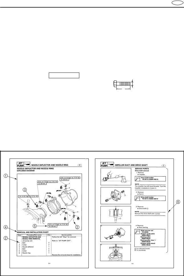
JET  PUMP
PUMP
78
|
|
|
|
|
|
|
|
|
|
|
|
|
ELEC |
|
|
|
|
|
|
|
|
|
HULL |
|
|
|
|
– + |
||||||||||
|
|
|
|
|
|
|
|
|
|
HOOD |
|
|
|
|
|
|
|
|
|
||||||
|
|
|
|
|
|
|
|
|
|
|
|
|
90
TRBL
ANLS
AB
CD
T .
R .
EF
E |
GH
A |
M |
IJ
GM |
4 |
KL
LT |
LT |
271 |
242 |
MN
LT |
SSLT |
|
572
E
A50001-1-4
SYMBOLS
Symbols 1 to 9 are designed as thumbtabs to indicate the content of a chapter.
1 General Information
2 Specifications
3 Periodic Inspection and Adjustment
4 Fuel System
5 Power Unit
6 Jet Pump Unit
7 Electrical System
8 Hull and Hood
9 Trouble analysis
Symbols 0 to E indicate specific data:
0 Special tool
A Specified liquid
B Specified engine speed C Specified torque
D Specified measurement
ESpecified electrical value
[Resistance (Ω), Voltage (V), Electric current (A)]
Symbol F to H in an exploded diagram indicate the grade of lubricant and the location of lubrication point:
FApply YAMALUBE 2-W oil or TC-W3 cirtified outboard oil
GApply water resistant grease
(Yamaha grease A, Yamaha marine grease)
H Apply molybdenum disulfide grease
Symbols I to N in an exploded diagram indicate the grade of the sealing or locking agent, and the location of the application point:
I Apply Gasket Maker®
JApply Yamabond #4 (Yamaha bond number 4)
K Apply LOCTITE® No. 271 (Red LOCTITE) L Apply LOCTITE® No. 242 (Blue LOCTITE) M Apply LOCTITE® No. 572
N Apply silicone sealant
NOTE:
In this manual, the above symbols may not be used in every case.
E
A30000-0 |
INDEX |
|
|
|
|
|
|
|
|
|
|
|
|
|
|
|
|
|
|
|
|
|
|
|
|
|
|
|
|
|
|
|
|
|
|
|
|
|
|
|
|
GENERAL INFORMATION |
|
|
|
|
|
|
|
|
|
|
1 |
|
|
|
INFOGEN |
|
|||||||||||
|
|
|
|
||||||||||
|
|
|
|
|
|
|
|
|
|
|
|
|
|
SPECIFICATIONS |
|
|
|
|
|
|
|
|
|
|
2 |
|
|
|
SPEC |
|
|||||||||||
|
|
|
|
||||||||||
|
|
|
|
|
|
|
|
|
|
|
|
|
|
|
|
|
|
|
|
|
|
|
|
|
|
|
|
PERIODIC INSPECTION AND |
|
|
|
|
|
|
|
|
|
|
3 |
|
|
ADJUSTMENT |
|
INSPADJ |
|
||||||||||
|
|
|
|
|
|
|
|
|
|
|
|
|
|
FUEL SYSTEM |
|
|
|
|
|
|
|
|
|
|
4 |
|
|
|
|
|
|
|
|
|
|
|
|
|
|||
|
FUEL |
|
|||||||||||
|
|
|
|
||||||||||
|
|
|
|
|
|
|
|
|
|
|
|
|
|
|
|
|
|
|
|
|
|
|
|
|
|
|
|
POWER UNIT |
|
|
|
|
|
|
|
|
|
|
|
5 |
|
|
|
|
|
|
|
|
|
|
|
|
|
||
|
|
|
|
|
|
|
|
|
|
|
|
||
|
POWR |
|
|||||||||||
|
|
|
|||||||||||
|
|
|
|
|
|
|
|
|
|
|
|
|
|
|
|
|
|
|
|
|
|
|
|
|
|
|
|
JET PUMP UNIT |
|
|
|
|
|
|
|
|
|
|
6 |
|
|
PUMPJET |
|
||||||||||||
|
|
|
|||||||||||
|
|
|
|
|
|
|
|
|
|
|
|
|
|
|
|
|
|
|
|
|
|
|
7 |
|
|||
|
|
|
|
– + |
|
|
|
||||||
ELECTRICAL SYSTEM |
|
|
|
|
|
|
|
|
|
|
|
||
|
|
|
|
|
|
|
|
|
|
|
|||
|
ELEC |
|
|||||||||||
|
|
|
|
||||||||||
|
|
|
|
|
|
|
|
|
|
|
|
|
|
|
|
|
|
|
|
|
|
|
|
|
|
|
|
HULL AND HOOD |
|
|
|
|
|
|
|
|
|
|
8 |
|
|
HOODHULL |
|
||||||||||||
|
|
|
|||||||||||
TROUBLE ANALYSIS |
9 |
ANLSTRBL |
|
|
|
|
|
|
GEN |
|
|
|
|
INFO |
|
|
E |
|
|
|
|
|
|
|
|
|
CHAPTER 1 |
|
|
|
|
GENERAL INFORMATION |
IDENTIFICATION NUMBERS......................................................................... |
1-1 |
PRIMARY l.D. NUMBER........................................................................... |
1-1 |
ENGINE SERIAL NUMBER ...................................................................... |
1-1 |
JET PUMP UNIT SERIAL NUMBER ........................................................ |
1-1 |
HULL IDENTIFICATION NUMBER (H.l.N.).............................................. |
1-1 |
SAFETY WHILE WORKING ...................................................................... |
1-2 |
FIRE PREVENTION................................................................................... |
1-2 |
VENTILATION........................................................................................... |
1-2 |
SELF-PROTECTION.................................................................................. |
1-2 |
OILS, GREASES AND SEALING FLUIDS................................................ |
1-2 |
GOOD WORKING PRACTICES................................................................ |
1-3 |
DISASSEMBLY AND ASSEMBLY........................................................... |
1-4 |
SPECIAL TOOLS............................................................................................. |
1-5 |
MEASURING ............................................................................................ |
1-5 |
REMOVAL AND INSTALLATION ............................................................ |
1-6 |
1
2
3
4
5
6
7
8
9
GEN INFO
IDENTIFICATION NUMBERS |
E |
A60700-0*
IDENTIFICATION NUMBERS
PRIMARY l.D. NUMBER
The primary l.D. number is stamped on a label attached to the inside of the engine compartment.
Starting primary l.D. number:
F0W: 800101–
ENGINE SERIAL NUMBER
The engine serial number is stamped on a label attached to the cylinder head.
Starting serial number: 68A: 000101–
JET PUMP UNIT SERIAL NUMBER
The jet pump unit serial number is stamped on a label attached to the intermediate housing.
Starting serial number: 68A: 800101–
HULL IDENTIFICATION NUMBER (H.l.N.)
The H.l.N. is stamped on a plate attached to the aft deck.
1-1
GEN INFO
SAFETY WHILE WORKING |
E |
 SAFETY WHILE WORKING
The procedures given in this manual are those recommended by Yamaha to be followed by Yamaha dealers and their mechanics.
FIRE PREVENTION
Gasoline (petrol) is highly flammable. Gasoline vapor is explosive if ignited.
Do not smoke while handling gasoline (petrol) and keep it away from heat, sparks, and open flames.
VENTILATION
Gasoline vapor is heavier than air and is deadly if inhaled in large quantities. Engine exhaust gases are harmful to breathe. When test-running an engine indoors, maintain good ventilation.
SELF-PROTECTION
Protect your eyes with suitable safety spectacles or safety goggles when grinding or doing any operation which may cause particles to fly off.
Protect hands and feet by wearing safety gloves or protective shoes if appropriate to the work you are doing.
OILS, GREASES AND SEALING FLUIDS
Use only genuine Yamaha oils, greases, and sealing fluids or those recommended by Yamaha.
1-2
GEN INFO
SAFETY WHILE WORKING |
E |
Under normal conditions of use there should be no hazards from the use of the lubricants mentioned in this manual, but safety is all-important, and by adopting good safety practises any risk is minimized. A summary of the most important precautions is as follows:
1.While working, maintain good standards of personal and industrial hygiene.
2.Clothing which has become contaminated with lubricants should be changed as soon as practicable and laundered before further use.
3.Avoid skin contact with lubricants (e.g., do not place a soiled rag in your pocket).
4.Hands and any other part of the body which have been in contact with lubricants or lubricant-contaminated clothing should be thoroughly washed with hot water and soap as soon as practicable.
5.To protect the skin, the application of a suitable barrier cream to the hands before working is recommended.
6.A supply of clean lint-free cloths should be available for wiping purposes.
GOOD WORKING PRACTICES
1.The right tools
Use the recommended special tools to protect parts from damage. Use the right tool in the right manner – do not improvise.
2.Tightening torque
Follow the tightening torque instructions. When tightening bolts, nuts and screws, tighten the larger sizes first and tighten inner-positioned fixings before outer-positioned ones.
1-3
GEN INFO
SAFETY WHILE WORKING |
E |
3.Non-reusable items
Always use new gaskets, packings, O- rings, oil seals, split-pins, circlips, etc., on reassembly.
DISASSEMBLY AND ASSEMBLY
1.Clean parts with compressed air when disassembling.
2.Oil the contact surfaces of moving parts during assembly.
3.After assembly, check that moving parts operate normally.
4.Install bearings with the manufacturer’s markings on the side exposed to view and liberally oil the bearings.
CAUTION:
Do not spin bearings with compressed air because this will damage their surfaces.
5.When installing oil seals, apply a light coat of water-resistant grease to the outside diameter.
1-4
GEN INFO
SPECIAL TOOLS
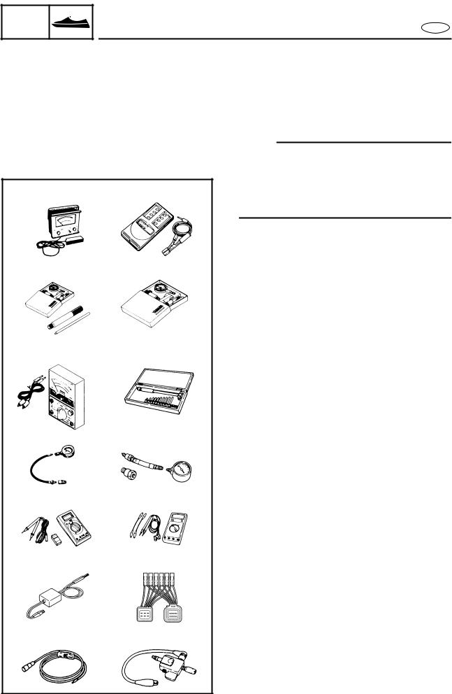
SPECIAL TOOLS
E
1 YU-8036-A |
90890-06760 |
2 YU-03097 |
90890-01252 |
YU-01256 |
|
3 YU-03112 |
4 YU-03017 |
90890-03112 |
90890-06759 |
5 YU-33223 |
90890-03160 |
6 J-39299 |
90890-06752 |
7 YU-39991 |
8 YW-06779 |
90890-03169 |
90890-06779 |
Using the correct special tools recommended by Yamaha, will aid the work and enable accurate assembly and tune-up. Improvisations and using improper tools can damage the equipment.
NOTE:
●For U.S.A. and Canada, use part numbers starting with “J-”, “YB-”, “YM-”, “YU-” or “YW-”.
●For other countries, use part numbers starting with “90890-”.
MEASURING
1Engine tachometer P/N. YU-8036-A
90890-06760
2 Dial gauge and stand P/N. YU-03097, YU-01256
90890-01252
3Pocket tester P/N. YU-03112
90890-03112
4 Cylinder gauge set P/N. YU-03017
90890-06759
5Compression gauge P/N. YU-33223
90890-03160
6Digital tester P/N. J-39299
90890-06752
7Peak voltage adapter P/N. YU-39991
90890-03169
8Peak voltage test harness P/N. YW-06779
90890-06779
9Spark gap tester P/N. YM-34487
90890-06754
9 YM-34487 |
90890-06754 |
1-5
|
|
|
|
|
|
|
|
|
|
GEN |
|
|
|
SPECIAL TOOLS |
|
|
|
|
INFO |
|
|
|
|
E |
||
|
|
|
|
|
|
|
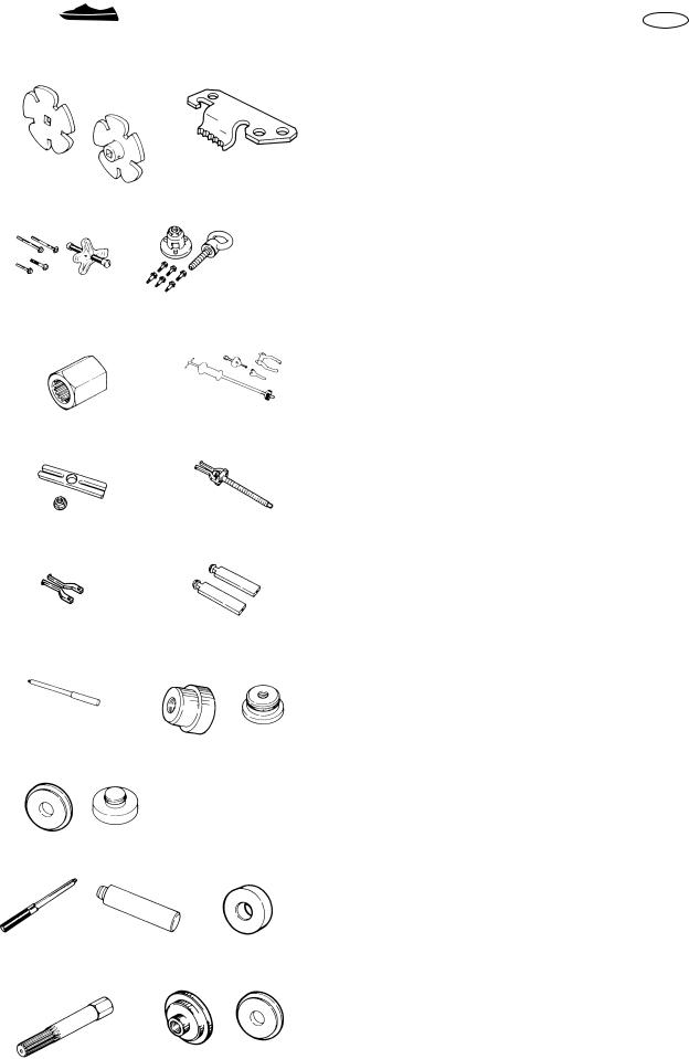
REMOVAL AND INSTALLATION |
|
|
|
|
|
|
|
|
||
|
1 YW-06551 |
|
|
2 YW-06550 |
90890-06550 |
|||
|
|
|
1 |
Coupler wrench |
||||
|
|
|
|
|
|
|
||
|
|
|
90890-06551 |
|
|
P/N. YW-06551 |
||
|
|
|
|
|
|
|
|
90890-06551 |
|
|
|
|
|
|
|
2 |
Flywheel holder |
|
|
|
|
|
|
|
|
P/N. YW-06550 |
|
|
|
|
|
|
|
|
90890-06550 |
|
3 YB-06117 |
90890-06521 |
|
3 |
Flywheel puller |
|||
|
|
|
P/N. YB-06117 |
|||||
|
|
|
|
|
|
|
|
|
|
|
|
|
|
|
|
|
90890-06521 |
|
|
|
|
|
|
|
4 |
Drive shaft holder (impeller) |
|
|
|
|
|
|
|
|
P/N. YB-06151 |
|
|
|
|
|
|
|
|
90890-06519 |
|
4 YB-06151 |
90890-06519 5 YB-06096 |
|
5 Slide hammer set (jet pump bearing) |
||||
|
|
|
|
|
|
|
|
P/N. YB-06096 |
|
|
|
|
|
|
|
6 |
Stopper guide plate (jet pump bearing) |
|
|
|
|
|
|
|
|
P/N. 90890-06501 |
|
|
|
|
|
|
|
7 |
Bearing puller (jet pump bearing) |
|
6 90890-06501 |
7 90890-06535 |
|
P/N. 90890-06535 |
||||
|
8 Bearing puller claw 1 (jet pump bearing) |
|||||||
|
|
|
|
|
|
|
|
P/N. 90890-06536 |
|
|
|
|
|
|
|
9 |
Stopper guide stand (jet pump bearing) |
|
|
|
|
|
|
|
|
P/N. 90890-06538 |
|
8 90890-06536 |
9 90890-06538 |
0 |
Drive rod L3 (jet pump bearing) |
||||
|
|
P/N. 90890-06652 |
||||||
|
|
|
|
|
|
|
|
|
|
|
|
|
|
|
|
A Needle bearing attachment |
|
|
|
|
|
|
|
|
|
(jet pump bearing and oil seal) |
|
|
|
|
|
|
|
|
P/N. YB-06112, YB-06196 |
|
0 90890-06652 |
|
|
A YB-06112 |
90890-06614 |
|
90890-06614, 90890-06653 |
|
|
|
|
B |
Ball bearing attachment |
||||
|
|
|
|
|
YB-06196 |
90890-06653 |
||
|
|
|
|
|
|
|
|
(jet pump oil seal) |
|
|
|
|
|
|
|
|
P/N. YB-06156 |
|
|
|
|
|
|
|
|
90890-06634 |
|
|
|
|
|
|
|
C Driver rod |
|
|
B YB-06156 90890-06634 |
|
|
(intermediate shaft and jet pump) |
||||
|
|
|
P/N. YB-06071 |
|||||
|
|
|
|
|
|
|
|
|
|
|
|
|
|
|
|
|
90890-06606 |
|
|
|
|
|
|
|
D Bearing inner/outer race attachment |
|
|
|
|
|
|
|
|
|
(jet pump bearing) |
|
C YB-06071 |
90890-06606 D YB-34474 |
|
P/N. YB-34474 |
||||
|
|
|
|
|
|
|
E Shaft holder (intermediate shaft) |
|
|
|
|
|
|
|
|
|
P/N. YB-06552 |
|
|
|
|
|
|
|
|
90890-06552 |
|
|
|
|
|
|
|
F Bearing outer race attachment |
|
|
E YB-06552 |
|
|
F YB-06016 90890-06626 |
|
(intermediate shaft) |
||
|
90890-06552 |
|
|
|
|
|
P/N. YB-06016 |
|
|
|
|
|
|
|
|
|
|
|
|
|
|
|
|
|
|
90890-06626 |
|
|
|
|
|
|
|
|
|
1-6

|
|
|
|
|
|
|
SPEC |
|
|
|
E |
|
|
|
|
|
|
|
|
|
|
CHAPTER 2 |
|
|
|
|
|
|
|
|
|
|
|
SPECIFICATIONS |
|
|
GENERAL SPECIFICATIONS.......................................................................... |
2-1 |
|||
|
MAINTENANCE SPECIFICATIONS................................................................ |
2-3 |
|||
|
|
ENGINE..................................................................................................... |
2-3 |
||
|
|
JET PUMP UNIT....................................................................................... |
2-4 |
||
|
|
HULL AND HOOD .................................................................................... |
2-4 |
||
|
|
ELECTRICAL ............................................................................................. |
2-5 |
||
|
TIGHTENING TORQUES................................................................................ |
2-7 |
|||
|
|
SPECIFIED TORQUES.............................................................................. |
2-7 |
||
|
|
GENERAL TORQUE ............................................................................... |
2-10 |
||
|
CABLE AND HOSE ROUTING...................................................................... |
2-11 |
|||
1
2
3
4
5
6
7
8
9

SPEC 


GENERAL SPECIFICATIONS |
E |
GENERAL SPECIFICATIONS
Item |
Unit |
Model |
|
GP800R |
|||
|
|
||
|
|
|
|
MODEL CODE |
|
|
|
Hull |
|
F0W |
|
Engine |
|
68A |
|
|
|
|
|
DIMENSIONS |
|
|
|
Length |
mm (in) |
2,930 (115.4) |
|
Width |
mm (in) |
1,150 (45.3) |
|
Height |
mm (in) |
1,020 (40.2) |
|
Dry weight |
kg (lb) |
268 (591) |
|
Watercraft capacity |
|
2 |
|
|
|
|
|
PERFORMANCE |
|
|
|
Maximum output |
kW (PS) @ r/min |
88.2 (120) @ 7,000 |
|
Maximum fuel consumption |
R/h (US gal/h, |
49 (12.9, 10.8) |
|
|
lmp gal/h) |
|
|
Cruising range |
h |
1.2 |
|
|
|
|
|
ENGINE |
|
|
|
Engine type |
|
2-stroke |
|
Number of cylinders |
|
2 |
|
Displacement |
cm3 (cu. in) |
784 (47.8) |
|
Bore × stroke |
mm (in) |
80.0 × 78.0 (3.15 × 3.07) |
|
Compression ratio |
|
6.6:1 |
|
Intake system |
|
Reed valve |
|
Carburetor model |
|
BN44 (Mikuni) × 2 |
|
(manufacturer) × quantity |
|
|
|
Enrichment control |
|
Choke valve |
|
Scavenging system |
|
Loop charge |
|
Lubrication system |
|
Oil injection |
|
Cooling system |
|
Water |
|
Starting system |
|
Electric |
|
Ignition system |
|
Digital CDI |
|
Ignition timing |
Degree |
15 BTDC–20 BTDC |
|
Spark plug model |
|
BR8ES (NGK) |
|
(manufacturer) |
|
|
|
Battery capacity |
V/Ah (kC) |
12/19 (68.4) |
|
Lighting coil |
max. A @ r/min |
8 @ 6,000 |
|
Propulsion system |
|
Jet pump |
|
|
|
|
|
DRIVE UNIT |
|
|
|
Jet pump type |
|
Axial flow, single stage |
|
Impeller rotation (from rear) |
|
Counterclockwise |
|
Transmission |
|
Direct drive from engine |
|
Nozzle angle (horizontal) |
Degree |
23 + 23 |
|
Nozzle angle (vertical) |
Degree |
–5, 0, 5, 10, 15 |
|
Trim system |
|
Manual 5 positions |
|
|
|
|
2-1

SPEC 


GENERAL SPECIFICATIONS |
E |
Item |
Unit |
Model |
|
GP800R |
|||
|
|
||
|
|
|
|
FUEL AND OIL |
|
|
|
Fuel |
|
Regular unleaded gasoline |
|
Fuel rating |
PON* |
86 |
|
|
RON* |
90 |
|
Oil |
|
YAMALUBE 2-W or an equivalent TC-W3 |
|
|
|
certified outboard oil |
|
Fuel/oil mixing ratio |
|
30:1 |
|
(wide open throttle) |
|
|
|
Fuel tank capacity |
R(US gal, |
60 (15.9, 13.2) |
|
|
Imp gal) |
|
|
Fuel tank reserve capacity |
R(US gal, |
10 (2.6, 2.2) |
|
|
Imp gal) |
|
|
Oil tank capacity |
R(US gal, |
5.5 (1.45, 1.21) |
|
|
Imp gal) |
|
PON*: Pump Octane Number = (Motor Octane Number + Research Octane Number)/2 RON*: Research Octane Number
2-2
|
|
|
|
|
|
SPEC |
|
|
MAINTENANCE SPECIFICATIONS |
|
|
|
|
|
MAINTENANCE SPECIFICATIONS
ENGINE
E
Item |
Unit |
Model |
|
GP800R |
|||
|
|
||
CYLINDER HEAD |
|
|
|
Warpage limit |
mm (in) |
0.1 (0.004) |
|
Compression pressure*1 |
kPa (kg/cm2) |
560 (5.6) |
|
CYLINDERS |
|
|
|
Bore size |
mm (in) |
80.000–80.018 (3.1496–3.1503) |
|
Taper limit |
mm (in) |
0.08 (0.003) |
|
Out-of-round limit |
mm (in) |
0.05 (0.002) |
|
Wear limit |
mm (in) |
Original cylinder bore + 0.04 (0.0016) |
|
PISTONS |
|
|
|
Diameter |
mm (in) |
Red: 79.899–79.902 (3.1456–3.1457) |
|
|
|
Orange: 79.903–79.906 (3.1458–3.1459) |
|
|
|
Green: 79.907–79.910 (3.1459–3.1461) |
|
|
|
Purple: 79.911–79.914 (3.1461–3.1462) |
|
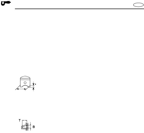
Measuring point* |
mm (in) |
22 (0.87) |
|
Piston-to-cylinder clearance |
mm (in) |
0.100–0.105 (0.0039–0.0041) |
|
Wear limit |
mm (in) |
Cylinder bore – 0.105 (0.0041) |
|
Piston pin bore inside |
mm (in) |
22.004–22.025 (0.8663–0.8671) |
|
diameter |
|
|
|
|
|
|
|
PISTON RINGS |
|
|
|
Top |
|
|
|
Type |
|
Keystone |
|
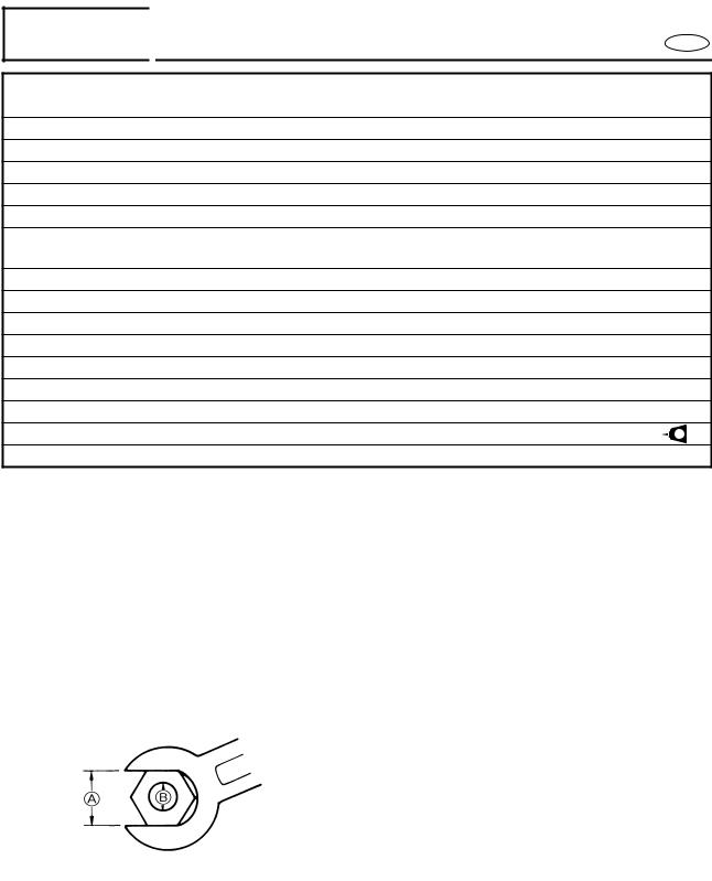
Dimensions (B) |
mm (in) |
1.2 (0.05) |
|
Dimensions (T) |
mm (in) |
2.85 (0.112) |
|
End gap |
mm (in) |
0.30–0.45 (0.012–0.018) |
|
Ring groove clearance |
mm (in) |
0.03–0.05 (0.001–0.002) |
|
2nd*2 |
|
|
|
Type |
|
Keystone |
|
Dimensions (B) |
mm (in) |
1.2 (0.05) |
|
Dimensions (T) |
mm (in) |
2.85 (0.112) |
|
End gap |
mm (in) |
0.30–0.45 (0.012–0.018) |
|
Ring groove clearance |
mm (in) |
0.03–0.05 (0.001–0.002) |
|
PISTON PINS |
|
|
|
Diameter |
mm (in) |
21.995–22.000 (0.8659–0.8661) |
|
Wear limit |
mm (in) |
21.990 (0.8657) |
*1: At 760 mmHg and 20 ˚C (68 ˚F)
*2: The top ring and 2nd ring are of the same type.
2-3
SPEC 


MAINTENANCE SPECIFICATIONS |
E |
Item |
Unit |
Model |
|
GP800R |
|||
|
|
||
CRANKSHAFT ASSEMBLY |
|
|
|
Crank width A |
mm (in) |
72.95–73.00 (2.872–2.874) |
|
Deflection limit B |
mm (in) |
0.05 (0.002) |
|
Big end side clearance C |
mm (in) |
0.25–0.75 (0.010–0.030) |
|
Maximum small end axial |
mm (in) |
2.0 (0.08) |
|
play D |
|
|
|
|
|
|
|
CARBURETORS |
|
|
|
Type |
|
Floatless |
|
Identification mark |
|
#1: 68A-01, #2: 68A-02 |
|
Main nozzle |
mm (in) |
3.0 (0.12) |
|
Main jet |
|
150 |
|
Pilot jet |
|
90 |
|
Throttle valve |
|
120 |
|
Valve seat size |
mm (in) |
1.2 (0.05) |
|
Trolling speed |
r/min |
1,300 ± 50 |
|
|
|
|
|
REED VALVES |
|
|
|
Thickness |
mm (in) |
0.52 (0.020) |
|
Reed valve stopper height |
mm (in) |
10.8–11.4 (0.43–0.45) |
|
Reed valve warpage limit |
mm (in) |
0.2 (0.01) |
|
JET PUMP UNIT |
|
|
|
|
|
|
|
Item |
Unit |
Model |
|
GP800R |
|||
|
|
||
JET PUMP |
|
|
|
Impeller material |
|
Stainless steel |
|
Number of impeller blades |
|
3 |
|
Impeller pitch angle |
Degree |
13.2 |
|
Impeller clearance |
mm (in) |
0.35–0.45 (0.014–0.018) |
|
Impeller clearance limit |
mm (in) |
0.6 (0.024) |
|
Drive shaft runout limit |
mm (in) |
0.3 (0.012) |
|
Nozzle diameter |
mm (in) |
86.8 (3.42) |
|
HULL AND HOOD |
|
|
|
|
|
|
|
Item |
Unit |
Model |
|
GP800R |
|||
|
|
||
FREE PLAY |
|
|
|
YPVS cable slack |
mm (in) |
0.5–1.5 (0.02–0.06) |
|
Throttle lever free play |
mm (in) |
4–7 (0.16–0.28) |
2-4

|
|
|
|
|
|
|
|
|
|
SPEC |
|
|
|
MAINTENANCE SPECIFICATIONS |
E |
||
|
|
|
|
|
|
|
|
|
|
ELECTRICAL |
|
|
|
|
|
|
|
|
|
|
|
|
|
|
|
|
|
|
Item |
Unit |
Model |
|
|||
|
|
GP800R |
|
|||||
|
|
|
|
|
|
|
|
|
|
|
|
|
|
|
|
|
|
|
BATTERY |
|
|
|
|
|
|
|
|
Type |
|
|
|
|
Fluid |
|
|
|
Capacity |
|
|
|
V/Ah (kC) |
12/19 (68.4) |
|
|
|
|
|
|
|
|
|
|
|
|
CDI UNIT |
|
|
(O – B) |
|
|
|
|
|
Output peak voltage lower |
|
|
|
||||
|
limit |
|
|
|
|
|
|
|
|
|
|
@cranking 1 |
V |
85 |
|
||
|
|
|
@cranking 2 |
V |
110 |
|
||
|
|
|
@2,000 r/min |
V |
205 |
|
||
|
|
|
@3,500 r/min |
V |
200 |
|
||
|
|
|
|
|
|
|
|
|
|
STATOR |
|
|
|
|
|
|
|
|
Charge coil |
|
|
(Br – L) |
|
|
|
|
|
Output peak voltage |
|
|
|
||||
|
lower limit |
|
|
|
|
|
|
|
|
|
|
@cranking 1 |
V |
90 |
|
||
|
|
|
@cranking 2 |
V |
120 |
|
||
|
|
|
@2,000 r/min |
V |
220 |
|
||
|
|
|
@3,500 r/min |
V |
210 |
|
||
|
Pickup coil |
(W/R – W/B) |
|
|
|
|||
|
Output peak voltage |
|
|
|
||||
|
lower limit |
|
|
|
|
|
|
|
|
|
|
@cranking 1 |
V |
5 |
|
||
|
|
|
@cranking 2 |
V |
3 |
|
||
|
|
|
@2,000 r/min |
V |
7 |
|
||
|
|
|
@3,500 r/min |
V |
11 |
|
||
|
Lighting coil |
|
|
(G – G) |
|
|
|
|
|
Output peak voltage |
|
|
|
||||
|
lower limit |
|
|
|
|
|
|
|
|
|
|
@cranking 1 |
V |
8.5 |
|
||
|
|
|
@cranking 2 |
V |
8.5 |
|
||
|
|
|
@2,000 r/min |
V |
13 |
|
||
|
|
|
@3,500 r/min |
V |
13 |
|
||
|
Charge coil resistance |
Ω (color) |
299–365 (Br – L) |
|
||||
|
Pickup coil resistance |
Ω (color) |
446–545 (W/R – W/B) |
|
||||
|
Lighting coil resistance |
Ω (color) |
0.86–1.06 (G – G) |
|
||||
|
Minimum charging current |
A @ r/min |
9 @ 6,000 |
|
||||
|
|
|
|
|
||||
|
IGNITION COIL |
|
|
|
||||
|
Minimum spark gap |
mm (in) |
10 (0.39) |
|
||||
|
Primary coil resistance |
Ω (color) |
0.078–0.106 (O – B) |
|
||||
|
Secondary coil resistance |
kΩ |
14.3–30.5 |
|
||||
(#1 Spark plug cap – #2 Spark plug cap)
Cranking 1: unloaded
Cranking 2: loaded
2-5

SPEC 


MAINTENANCE SPECIFICATIONS |
E |
Item |
Unit |
Model |
||
GP800R |
||||
|
|
|||
|
|
|
|
|
RECTIFIER/REGULATOR |
|
|
|
|
(R – B) |
|
|
|
|
Output peak voltage lower |
|
|
|
|
limit (unloaded) |
|
|
|
|
@cranking |
V |
|
7.5 |
|
@2,000 r/min |
V |
12.5 |
||
@3,500 r/min |
V |
12.5 |
||
|
|
|
|
|
THERMO SWITCH |
|
|
|
|
On temperature |
˚C (˚F) |
80 |
(177) |
|
Off temperature |
˚C (˚F) |
70 |
(159) |
|
|
|
|
|
|
STARTER MOTOR |
|
|
|
|
Brush length |
mm (in) |
12.5 (0.49) |
||
Wear limit |
mm (in) |
6.5 |
(0.26) |
|
Commutator undercut |
mm (in) |
0.7 |
(0.03) |
|
Limit |
mm (in) |
0.2 |
(0.01) |
|
Commutator diameter |
mm (in) |
28.0 (1.10) |
||
Limit |
mm (in) |
27.0 (1.06) |
||
|
|
|
|
|
FUSE |
|
|
|
|
Rating |
V/A |
12/10 |
||
|
|
|
|
|
2-6
SPEC 


TIGHTENING TORQUES |
E |
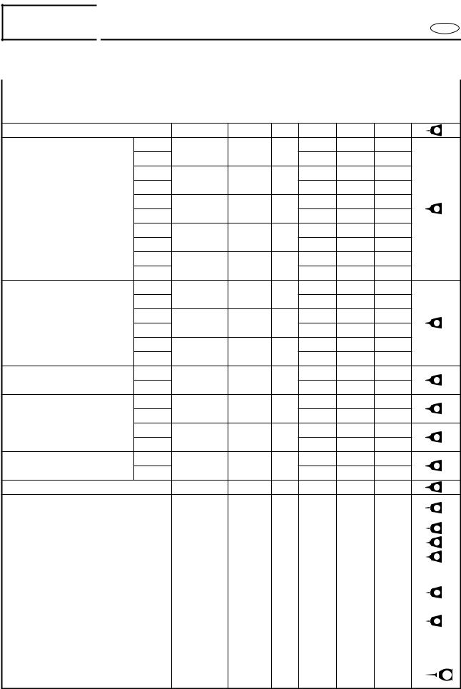
TIGHTENING TORQUES
SPECIFIED TORQUES
Part to tightened |
Part name |
Thread |
Q’ty |
Tightening torque |
Remarks |
|||
size |
N•m |
kgf•m |
ft•lb |
|||||
|
|
|
|
|||||
|
|
|
|
|
|
|
|
|
ENGINE UNIT
Engine unit – engine mount |
|
Bolt |
M8 |
4 |
17 |
1.7 |
12 |
LT |
572 |
|
|
1st |
Bolt |
M10 |
2 |
2 |
0.2 |
1.4 |
|
|
|
|
4th |
51 |
5.1 |
37 |
|
|
||||
|
|
|
|
|
|
|||||
|
2nd |
Bolt |
M10 |
4 |
2 |
0.2 |
1.4 |
|
|
|
|
6th |
39 |
3.9 |
28 |
|
|
||||
Exhaust chamber |
|
|
|
|
|
|||||
3rd |
Nut |
M10 |
2 |
2 |
0.2 |
1.4 |
|
|
||
assembly – muffler stay 1 |
LT |
271 |
||||||||
5th |
51 |
5.1 |
37 |
|||||||
– muffler stay 3 |
|
|
|
|
|
|||||
7th |
|
|
|
2 |
0.2 |
1.4 |
|
|
||
|
Bolt |
M10 |
1 |
|
|
|||||
|
9th |
49 |
4.9 |
35 |
|
|
||||
|
|
|
|
|
|
|||||
|
8th |
Bolt |
M10 |
1 |
2 |
0.2 |
1.4 |
|
|
|
|
10th |
49 |
4.9 |
35 |
|
|
||||
|
|
|
|
|
|
|||||
|
1st |
Nut |
M8 |
2 |
15 |
1.5 |
11 |
|
|
|
|
2nd |
39 |
3.9 |
28 |
|
|
||||
|
|
|
|
|
|
|||||
Exhaust chamber – |
1st |
Bolt |
M8 |
3 |
15 |
1.5 |
11 |
LT |
271 |
|
muffler |
2nd |
33 |
3.3 |
24 |
||||||
|
|
|
|
|
||||||
|
1st |
Nut |
M10 |
1 |
15 |
1.5 |
11 |
|
|
|
|
2nd |
51 |
5.1 |
37 |
|
|
||||
|
|
|
|
|
|
|||||
Exhaust chamber joint – |
1st |
Bolt |
M8 |
5 |
17 |
1.7 |
12 |
LT |
271 |
|
exhaust manifold |
2nd |
34 |
3.4 |
24 |
||||||
|
|
|
|
|
||||||
|
1st |
Bolt |
M10 |
1 |
2 |
0.2 |
1.4 |
LT |
271 |
|
Exhaust chamber joint – |
3rd |
49 |
4.9 |
35 |
||||||
|
|
|
|
|
||||||
muffler stay |
2nd |
Bolt |
M8 |
2 |
2 |
0.2 |
1.4 |
LT |
271 |
|
|
4th |
37 |
3.7 |
27 |
||||||
|
|
|
|
|
|
|||||
Exhaust manifold – |
1st |
Bolt |
M10 |
8 |
23 |
2.3 |
17 |
LT |
271 |
|
cylinder |
2nd |
51 |
5.1 |
37 |
||||||
|
|
|
|
|
||||||
Reed valve – reed valve seat |
Screw |
M3 |
16 |
0.8 |
0.08 |
0.58 |
LT |
242 |
||
YPVS cable bracket – YPVS cover |
Bolt |
M6 |
2 |
10 |
1.0 |
7.2 |
LT |
572 |
|||
– cylinder |
|||||||||||
|
|
|
|
|
|
|
|
|
|||
|
|
|
|
|
|
|
|
|
|||
YPVS cover – cylinder |
Bolt |
M6 |
6 |
10 |
1.0 |
7.2 |
LT |
572 |
|||
|
|
|
|
|
|
|
|
|
|||
YPVS valve assembly – cylinder |
Bolt |
M5 |
2 |
4 |
0.4 |
2.9 |
LT |
271 |
|||
|
|
|
|
|
|
|
|
|
|||
YPVS valve lever – shaft |
Bolt |
M4 |
2 |
3 |
0.3 |
2.2 |
LT |
242 |
|||
|
|
|
|
|
|
|
|
|
|
||
Spark plug – cylinder head |
Spark plug |
M14 |
2 |
25 |
2.5 |
18 |
|
|
|
||
|
|
|
|
|
|
|
|
|
|
|
|
Cylinder head – cylinder |
1st |
Bolt |
M8 |
10 |
15 |
1.5 |
11 |
LT |
572 |
||
|
|
|
|
||||||||
2nd |
37 |
3.7 |
27 |
||||||||
|
|
|
|
|
|
|
|||||
|
|
|
|
|
|
|
|
|
|
|
|
Cylinder – crankcase |
1st |
Bolt |
M10 |
8 |
22 |
2.2 |
16 |
LT |
572 |
||
|
|
|
|
||||||||
2nd |
39 |
3.9 |
28 |
||||||||
|
|
|
|
|
|
|
|||||
|
|
|
|
|
|
|
|
|
|
|
|
Starter motor lead – starter |
|
Nut |
M6 |
1 |
5 |
0.5 |
3.6 |
|
|
|
|
motor |
|
|
|
||||||||
|
|
|
|
|
|
|
|
|
|||
|
|
|
|
|
|
|
|
|
|
||
Flywheel magneto – crankshaft |
Bolt |
M10 |
1 |
74 |
7.4 |
53 |
|
|
E |
||
assembly |
|
|
|||||||||
|
|
|
|
|
|
|
|
|
|||
2-7
SPEC 


TIGHTENING TORQUES |
E |
Part to tightened |
|
|
Part name |
|
Thread |
|
|
|
|
|
|
|
size |
Drive coupling – crankshaft |
|
|
Drive |
|
M27 |
|
assembly |
|
|
coupling |
|
||
|
|
|
|
|||
|
1st |
|
|
|
|
|
Generator cover – |
|
|
Bolt |
|
M8 |
|
crankcase |
|
2nd |
|
|
||
|
|
|
|
|
||
Pickup coil – generator cover |
|
Bolt |
|
M5 |
||
Cable holder – generator cover |
|
Bolt |
|
M6 |
||
Stator coil – generator cover |
|
Bolt |
|
M6 |
||
Lower crankcase – upper |
|
1st |
|
|
|
M8 |
|
|
|
|
|||
|
|
|
Bolt |
|
||
|
2nd |
|
|
|||
crankcase |
|
|
|
|
||
|
|
|
|
|
M6 |
|
|
|
|
|
|
||
|
|
|
|
|
|
|
|
1st |
|
|
|
|
|
Mount bracket – |
|
|
Bolt |
|
M8 |
|
crankcase |
|
2nd |
|
|
||
|
|
|
|
|
||
JET PUMP UNIT |
|
|
|
|
|
|
Steering cable joint – nozzle |
|
|
Nut |
|
M6 |
|
|
|
|
||||
deflector |
|
|
|
|||
|
|
|
|
|
||
Ride plate – hull |
|
|
Bolt |
|
M8 |
|
Intake duct – hull |
|
|
Bolt |
|
M8 |
|
Intake grate – hull |
|
|
Bolt |
|
M6 |
|
Speed sensor – ride plate |
|
|
Screw |
|
M5 |
|
Nozzle ring – nozzle |
|
|
Bolt |
|
M8 |
|
Nozzle deflector – nozzle ring |
|
Bolt |
|
M8 |
||
Water inlet cover – water inlet |
|
Bolt |
|
M6 |
||
strainer – impeller duct |
|
|
|
|||
|
|
|
|
|
||
Drive shaft nut – drive shaft |
|
|
Nut |
|
M16 |
|
Impeller (left-hand threads) – |
|
Impeller |
|
M22 |
||
drive shaft |
|
|
|
|||
|
|
|
|
|
||
Transom plate – hull |
|
|
Nut |
|
M10 |
|
Bilge strainer holder – bulkhead |
|
Screw |
|
M5 |
||
Intermediate housing – bulkhead |
|
Bolt |
|
M8 |
||
Driven coupling – shaft |
|
|
Driven |
|
M27 |
|
|
|
coupling |
|
|||
|
|
|
|
|
|
|
Grease nipple – intermediate |
|
Nipple |
|
— |
||
housing |
|
|
|
|||
|
|
|
|
|
||
HULL AND HOOD |
|
|
|
|
|
|
Handlebar cover – handlebar |
|
Screw |
|
M6 |
||
|
|
|||||
cover stay |
|
|
|
|||
|
|
|
|
|
||
Handlebar cover stay – steering |
|
Screw |
|
M6 |
||
column |
|
|
|
|||
|
|
|
|
|
||
Upper handlebar holder/lower |
|
Bolt |
|
M8 |
||
handle holder – steering column |
|
|
||||
|
|
|
|
|||
QSTS converter – hull |
|
|
Nut |
|
M6 |
|
QSTS cable 1, 2 locknut |
|
|
Nut |
|
M8 |
|
Throttle lever assembly – |
|
|
Screw |
|
M5 |
|
handlebar |
|
|
|
|||
|
|
|
|
|
||
|
|
|
|
|
|
|
2-8
Q’ty |
Tightening torque |
|
Remarks |
||||
N•m |
kgf•m |
|
ft•lb |
|
|||
1 |
36 |
3.6 |
|
25 |
|
LT |
572 |
8 |
15 |
1.5 |
|
11 |
|
LT |
271 |
|
|
|
|
|
|||
27 |
2.7 |
|
19 |
|
|||
|
|
|
|
|
|||
2 |
5 |
0.5 |
|
3.6 |
|
LT |
242 |
2 |
14 |
1.4 |
|
10 |
|
LT |
242 |
3 |
14 |
1.4 |
|
10 |
|
LT |
242 |
13 |
15 |
1.5 |
|
11 |
|
|
|
|
|
|
|
|
|
|
|
27 |
2.7 |
|
19 |
|
LT |
572 |
|
|
|
|
|||||
7 |
11 |
1.1 |
|
8.0 |
|
|
|
6 |
15 |
1.5 |
|
11 |
|
LT |
271 |
|
|
|
|
|
|||
27 |
2.7 |
|
19 |
|
|||
|
|
|
|
|
|||
1 |
|
0.7 |
|
5.1 |
|
LT |
242 |
7 |
|
|
|||||
4 |
17 |
1.7 |
|
12 |
|
LT |
572 |
4 |
17 |
1.7 |
|
12 |
|
|
|
|
LT |
572 |
|||||
4 |
7 |
0.7 |
|
5.1 |
|
|
|
|
|
LT |
572 |
||||
4 |
4 |
0.4 |
|
2.9 |
|
|
|
|
|
LT |
242 |
||||
2 |
15 |
1.5 |
|
11 |
|
LT |
271 |
2 |
15 |
1.5 |
|
11 |
|
LT |
271 |
4 |
7 |
0.7 |
|
5.1 |
|
LT |
572 |
1 |
74 |
7.4 |
|
53 |
|
|
|
1 |
18 |
1.8 |
|
13 |
|
LT |
572 |
4 |
26 |
2.6 |
|
19 |
|
|
|
1 |
4 |
0.4 |
|
2.9 |
|
|
|
3 |
17 |
1.7 |
|
12 |
|
LT |
572 |
1 |
36 |
3.6 |
|
25 |
|
LT |
572 |
1 |
5 |
0.5 |
|
3.6 |
|
LT |
572 |
4 |
|
0.11 |
|
0.8 |
|
|
|
|
|
|
|
|
|||
1.1 |
|
|
|
|
|||
4 |
2.9 |
0.29 |
|
2.1 |
|
|
|
4 |
16 |
1.6 |
|
11 |
|
|
|
2 |
5 |
0.5 |
|
3.6 |
|
|
|
2 |
16 |
1.6 |
|
11 |
|
|
|
2 |
3 |
0.3 |
|
2.2 |
|
|
|
|
|
|
|
|
|
|
|

SPEC 


TIGHTENING TORQUES |
E |
Part to tightened
Handlebar switch assembly – handlebar
QSTS grip assembly – handlebar
Grip end – handlebar
Choke lever assembly – handlebar
QSTS cable housing – cover
Plate/steering column assembly
– deck
Steering column assembly – deck
Steering arm – steering column
Steering cable ball joint – steering arm
Handlebar stopper – steering column housing
QSTS cable locknut (nozzle ring side)
QSTS cable – hull
QSTS cable end – pin – QSTS converter
Steering cable locknut (nozzle deflector side)
Steering cable – hull
Steering cable holder – bracket
Speed sensor lead – hull
Hinge assembly – front hood
Wind shield – front hood
Hood lock – front hood
Hinge assembly – deck
Steering console cover assembly
– deck
Multifunction meter – holder
Steering console cover – side cover
Steering console cover – glove compartment
Steering cable bracket – deck
Buzzer bracket – deck – steering cable bracket
Hood lock assembly – deck
Seat lock assembly – seat
Bracket/deck – notch
Bracket/deck – hand grip
Part name |
Thread |
Q’ty |
Tightening torque |
Remarks |
|||
size |
N•m |
kgf•m |
ft•lb |
||||
|
|
|
|||||
Screw |
M5 |
2 |
3 |
0.3 |
2.2 |
|
|
Screw |
M6 |
1 |
3 |
0.3 |
2.2 |
|
|
Bolt |
M5 |
2 |
1 |
0.1 |
0.7 |
|
|
Screw |
M5 |
2 |
3 |
0.3 |
2.2 |
|
|
Screw |
M4 |
1 |
1 |
0.1 |
0.7 |
|
|
Nut |
M8 |
2 |
16 |
1.6 |
11 |
|
|
Nut |
M8 |
2 |
16 |
1.6 |
11 |
|
|
Nut |
M8 |
1 |
16 |
1.6 |
11 |
|
|
Nut |
M6 |
1 |
5 |
0.5 |
3.6 |
|
|
Nut |
M10 |
1 |
26 |
2.6 |
19 |
|
|
Nut |
M5 |
1 |
3 |
0.3 |
2.2 |
|
|
Nut |
— |
1 |
6 |
0.6 |
4.3 |
|
|
Nut |
M6 |
1 |
4 |
0.4 |
2.9 |
|
|
Nut |
M6 |
1 |
6 |
0.6 |
4.3 |
|
|
Nut |
— |
1 |
6 |
0.6 |
4.3 |
|
|
Bolt |
M6 |
1 |
6 |
0.6 |
4.3 |
|
|
Nut |
— |
1 |
6 |
0.6 |
4.3 |
|
|
Bolt |
M6 |
2 |
12 |
1.2 |
8.7 |
|
|
Screw |
M5 |
8 |
1 |
0.1 |
0.7 |
|
|
Bolt |
M6 |
2 |
5 |
0.5 |
3.6 |
|
|
Nut |
M8 |
2 |
16 |
1.6 |
11 |
|
|
Nut |
M6 |
2 |
5 |
0.5 |
3.6 |
|
|
|
|
|
|
|
|
|
|
Bolt |
M6 |
4 |
3 |
0.3 |
2.2 |
|
|
|
|
|
|
|
|
|
|
Screw |
M5 |
2 |
2 |
0.2 |
1.4 |
|
|
|
|
|
|
|
|
|
|
Nut |
M8 |
2 |
16 |
1.6 |
11 |
|
|
Nut |
M5 |
2 |
2 |
0.2 |
1.4 |
|
|
Screw |
M6 |
4 |
3 |
0.3 |
2.2 |
|
|
Screw |
M5 |
4 |
1 |
0.1 |
0.7 |
|
|
Bolt |
M6 |
1 |
6 |
0.6 |
4.3 |
|
|
Bolt |
M6 |
2 |
6 |
0.6 |
4.3 |
|
|
Nut |
M6 |
2 |
6 |
0.6 |
4.3 |
|
|
Bolt |
M6 |
2 |
6 |
0.6 |
4.3 |
LT 572 |
|
Nut |
M10 |
1 |
26 |
2.6 |
19 |
|
|
Bolt |
M8 |
2 |
5 |
0.5 |
3.6 |
|
|
|
|
|
|
|
|
|
|
2-9
SPEC 


TIGHTENING TORQUES
E
Part to tightened |
Part name |
Thread |
Q’ty |
Tightening torque |
|||
size |
N•m |
kgf•m |
ft•lb |
||||
|
|
|
|||||
Hand grip – deck |
Nut |
M8 |
2 |
5 |
0.5 |
3.6 |
|
Seat bracket – deck |
Nut |
M8 |
2 |
15 |
1.5 |
11 |
|
Battery box/stay – holder |
Nut |
M6 |
2 |
9 |
0.9 |
6.5 |
|
Battery box – bracket/deck |
Nut |
M8 |
2 |
13 |
1.3 |
9.4 |
|
Battery box – electrical box |
Bolt |
M8 |
3 |
15 |
1.5 |
11 |
|
Extension bolt – battery negative |
Bolt |
M6 |
1 |
6 |
0.6 |
4.3 |
|
terminal |
|||||||
|
|
|
|
|
|
||
Exhaust outlet – hull |
Bolt |
M6 |
3 |
6 |
0.6 |
4.3 |
|
Sponson – hull |
Bolt |
M8 |
6 |
18 |
1.8 |
13 |
|
Spout – hull |
Nut |
M24 |
1 |
5 |
0.5 |
3.6 |
|
Rope hole – hull |
Nut |
M24 |
2 |
5 |
0.5 |
3.6 |
|
Bow eye – hull |
Bolt |
M6 |
2 |
13 |
1.3 |
9.4 |
|
Flap – hull |
Bolt |
M6 |
8 |
6 |
0.6 |
4.3 |
|
Drain plug/packing – hull |
Nut |
M5 |
4 |
2 |
0.2 |
1.4 |
|
Engine mount – hull |
Bolt |
M8 |
8 |
17 |
1.7 |
12 |
|
Engine damper – hull |
Bolt |
M6 |
2 |
6 |
0.6 |
4.3 |
|
|
|
|
|
|
|
|
|
Remarks
LT |
572 |
|
|
General torque |
||
Nut A |
Bolt B |
specifications |
||
|
|
N•m |
kgf•m |
ft•lb |
|
|
|
|
|
8 mm |
M5 |
5.0 |
0.5 |
3.6 |
10 mm |
M6 |
8.0 |
0.8 |
5.8 |
12 mm |
M8 |
18 |
1.8 |
13 |
14 mm |
M10 |
36 |
3.6 |
25 |
17 mm |
M12 |
43 |
4.3 |
31 |
|
|
|
|
|
|
|
|
|
|
|
|
|
|
|
GENERAL TORQUE
This chart specifies tightening torques for standard fasteners with a standard ISO thread pitch. Tightening torque specifications for special components or assemblies are provided in applicable sections of this manual. To avoid warpage, tighten multifastener assemblies in a crisscross fashion and progressive stages until the specified tightening torque is reached. Unless otherwise specified, tightening torque specifications require clean, dry threads.
Components should be at room temperature.
2-10

|
|
|
|
|
|
SPEC |
|
|
CABLE AND HOSE ROUTING |
|
|
|
|
|
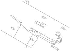
CABLE AND HOSE ROUTING
E
|
|
2 |
|
|
|
|
|
A |
|
|
|
|
|
|
|
|
|
F |
|
|
|
|
|
|
|
|
|
|
|
|
|
A |
2 |
1 |
B |
|
|
|
C B |
|
|
|
|
|
|
L |
K |
K |
|
E |
|
|
|
|
|
|
|
|
|
|
||
|
20˚ |
E |
|
D |
D |
|
|
|
|
|
|
|
2 |
2 |
|||
|
|
|
|
|
|
|
||
|
|
E |
|
|
E |
|
|
C |
|
|
|
|
F |
|
|
||
|
K |
|
|
|
|
|
|
|
B |
|
|
|
F |
|
|
2 |
|
|
|
|
|
|
|
|
||
L |
|
|
K |
|
|
|
|
|
|
A |
K |
|
|
|
|
3 |
|
9 |
|
|
|
|
|
|
|
|
|
|
|
|
|
|
|
D-D |
|
0 |
|
J |
J |
G |
G |
|
|
|
|
J |
J |
J |
|
|
|
|
4 |
K-K |
I |
|
|
|
|
|||
|
|
|
|
|
|
|
||
9 |
|
I |
I |
H |
H |
|
|
E-E |
0 |
|
|
|
|
|
|
|
|
A |
|
|
|
|
|
|
|
|
J-J |
H |
|
|
|
|
C |
|
|
G |
|
|
|
|
|
|
|
|
|
|
|
|
|
|
|
|
|
9 |
|
|
|
|
|
D |
5 |
|
|
|
|
|
|
|
|
|
|
0 |
|
|
|
|
|
E |
6 |
|
|
|
|
|
|
|
|
||
|
|
|
|
|
|
F |
7 |
|
I-I |
|
|
|
|
|
|
F-F |
|
|
|
|
|
|
|
|
||
|
|
|
|
|
|
|
|
|
|
9 |
|
|
|
|
|
|
|
8 |
|
|
|
|
|
|
|
4 |
H-H |
|
|
|
|
|
|
|
G-G |
1 Fuel filter |
9 Speed sensor lead |
G Battery breather hose |
2 Fuel tank breather hose |
0 Electrical box lead |
H Battery positive lead |
3 Fuel hose |
A YPVS cables |
I Starter motor lead |
4 Cooling water hose |
B Cooling water pilot outlet |
J Generator lead |
5 Choke cable |
C Battery negative lead |
K YPVS servomotor |
6 Throttle cable |
D Battery |
|
7 Oil return hose |
E Steering cable |
|
8 Bilge hose |
F QSTS cable |
|
|
2-11 |
|

SPEC 


CABLE AND HOSE ROUTING
E
 D
D
|
|
|
1 |
2 |
3 |
|
|
D |
|
||
|
|
|
|
|
|
|
E |
E |
D |
|
E |
|
|
|
|
||
A |
B |
C |
|
|
|
|
H |
|
|
|
|
A |
I |
|
|
|
|
|
2 J K |
|
|
|
|
|
B |
|
|
L |
|
|
|
|
|
|
|
|
|
|
|
M |
|
|
|
|
|
5 |
|
 J
J
I
 F
F
C
J |
E A F |
G 7 4 |
0 A |
8 |
4 |
|
||
E |
|
G-G |
A |
|
|
F |
|
9 |
G |
|
|
H |
G |
G |
H |
|
J-J |
|
|
|
|
|
F E D C B |
7 |
6 |
5 |
4 |
|
|
|
|
|
||
I |
H-H |
|
F |
|
|
1 Oil delivery hose |
9 Bilge hoses |
F To thermoswitch |
|||
2 Fuel return hose |
0 To multifunction meter |
G Battery negative lead |
|||
3 Fuel suction hose |
A To stator assembly |
H Buzzer lead |
|
|
|
4 Speed sensor lead |
B To cylinder #1 |
I Choke cable |
|
|
|
5 QSTS cable |
C To cylinder #2 |
J YPVS servomotor |
|||
6 Cooling water hose |
D To battery positive terminal |
K YPVS cables |
|
|
|
7 Steering cable |
E To starter motor positive |
L Battery positive lead |
|||
8 Flushing hose |
terminal |
M Battery breather hose |
|||
|
2-12 |
|
|
|
|
 Loading...