


FOREWORD
This Supplementary Service Manual has been prepared to introduce new service and data for the FZ6-N(S) 2004. For complete service information procedures it is necessary to use this Supplementary Service Manual together with the following manual.
FZ6-S(S) 2004 SERVICE MANUAL: 5VX1-AE1
FZ6-N(S) 2004
SUPPLEMENTARY
SERVICE MANUAL E2003 by Yamaha Motor Co., Ltd.
First Edition, December 2003 All rights reserved.
Any reproduction or unauthorized use without the written permission of Yamaha Motor Co., Ltd.
is expressly prohibited.
EAS00002
NOTICE
This manual was produced by the Yamaha Motor Company, Ltd. primarily for use by Yamaha dealers and their qualified mechanics. It is not possible to include all the knowledge of a mechanic in one manual. Therefore, anyone who uses this book to perform maintenance and repairs on Yamaha vehicles should have a basic understanding of mechanics and the techniques to repair these types of vehicles. Repair and maintenance work attempted by anyone without this knowledge is likely to render the vehicle unsafe and unfit for use.
Yamaha Motor Company, Ltd. is continually striving to improve all of its models. Modifications and significant changes in specifications or procedures will be forwarded to all authorized Yamaha dealers and will appear in future editions of this manual where applicable.
NOTE:
Designs and specifications are subject to change without notice.
EAS00004
IMPORTANT MANUAL INFORMATION
Particularly important information is distinguished in this manual by the following.
|
|
The Safety Alert Symbol means ATTENTION! BECOME ALERT! YOUR |
|||
|
|
SAFETY IS INVOLVED! |
|||
WARNING |
Failure to follow WARNING instructions could result in severe injury or death to |
||||
|
|
|
|||
the motorcycle operator, a bystander or a person checking or repairing the mo- |
|||||
|
|
||||
|
|
torcycle. |
|||
|
|
A CAUTION indicates special precautions that must be taken to avoid damage |
|||
CAUTION: |
|
||||
|
|
to the motorcycle. |
|||
NOTE: |
|||||
A NOTE provides key information to make procedures easier or clearer. |
|||||
EAS00007
HOW TO USE THIS MANUAL
This manual is intended as a handy, easy-to-read reference book for the mechanic. Comprehensive explanations of all installation, removal, disassembly, assembly, repair and check procedures are laid out with the individual steps in sequential order.
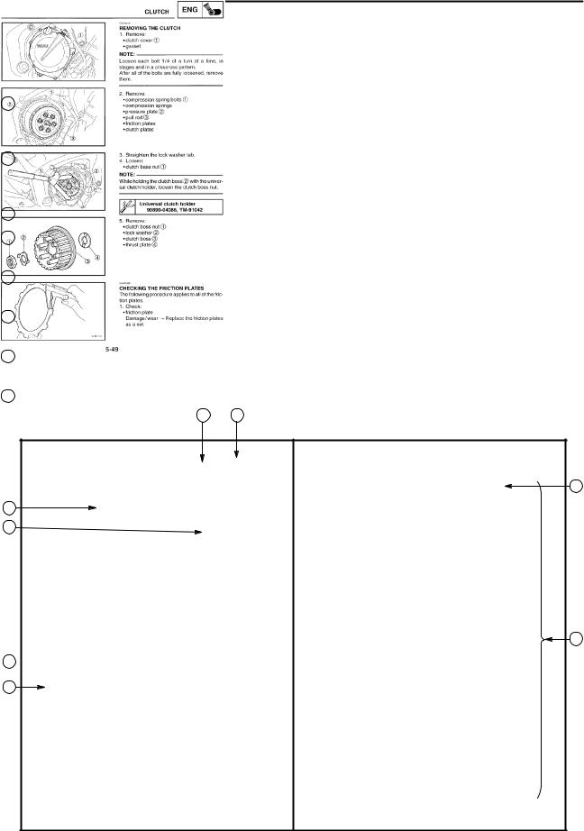
1The manual is divided into chapters. An abbreviation and symbol in the upper right corner of each page indicate the current chapter.
Refer to “SYMBOLS”.
2Each chapter is divided into sections. The current section title is shown at the top of each page, except in Chapter 3 (“PERIODIC CHECKS AND ADJUSTMENTS”), where the sub-section title(s) appears.
3Sub-section titles appear in smaller print than the section title.
4To help identify parts and clarify procedure steps, there are exploded diagrams at the start of each removal and disassembly section.
5Numbers are given in the order of the jobs in the exploded diagram. A circled number indicates a disassembly step.
6Symbols indicate parts to be lubricated or replaced.
Refer to “SYMBOLS”.
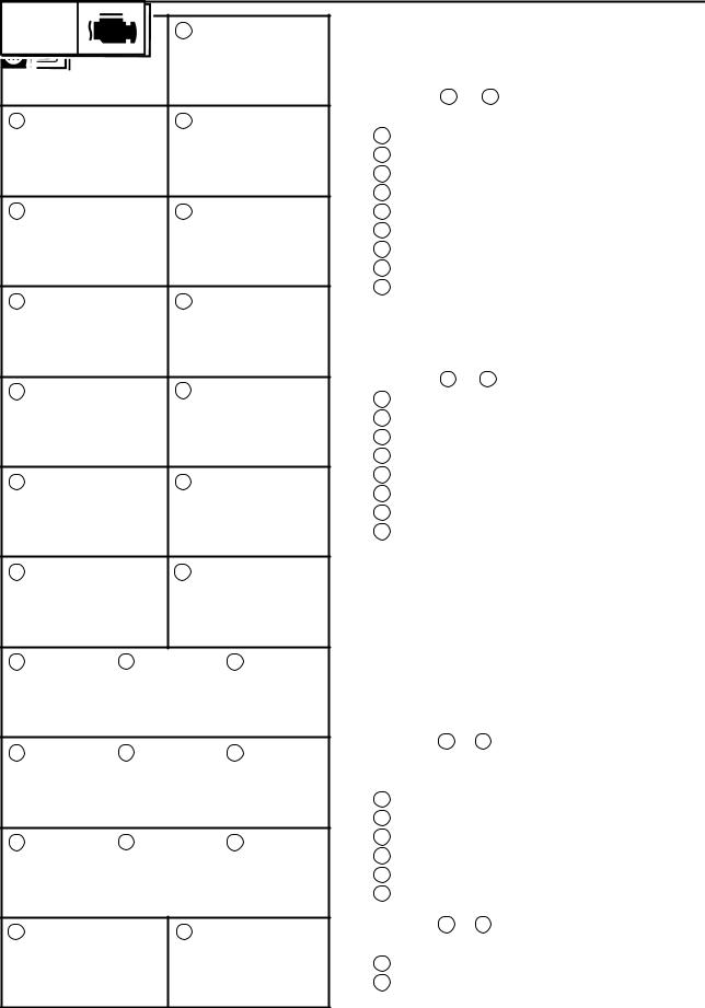
7A job instruction chart accompanies the exploded diagram, providing the order of jobs, names of parts, notes in jobs, etc.
8Jobs requiring more information (such as special tools and technical data) are described sequen-
tially. |
2 |
1 |
3
4
5
8
6 
7
1 |
2 |
GEN |
SPEC |
|
INFO |
||
|
||
3 |
4 |
|
CHK |
CHAS |
|
ADJ |
||
|
||
5 |
6 |
|
ENG |
COOL |
|
7 |
8 |
|
|
ELEC |
|
9 |
10 |
|
TRBL |
|
|
SHTG |
|
|
11 |
12 |
13 |
14 |
15 |
16 |
17 |
18 |
19 |
20 |
21 |
22 |
23 |
24 |
25 |
EAS00008
SYMBOLS
The following symbols are not relevant to every vehicle.
Symbols 1 to 9 indicate the subject of each chapter.
1General information
2Specifications
3Periodic checks and adjustments
4Chassis
5Engine
6Cooling system
7Fuel injection system
8Electrical system
9Troubleshooting
Symbols 10 to 17 indicate the following.
10Serviceable with engine mounted
11Filling fluid
12Lubricant
13Special tool
14Tightening torque
15Wear limit, clearance
16Engine speed
17Electrical data
Symbols 18 to 23 in the exploded diagrams indicate the types of lubricants and lubrication points.
18Engine oil
19Gear oil
20Molybdenum-disulfide oil
21Wheel-bearing grease
22Lithium-soap-based grease
23Molybdenum-disulfide grease
Symbols 24 to 25 in the exploded diagrams indicate the following.
24Apply locking agent (LOCTITE )
25Replace the part

CONTENTS
SPECIFICATIONS
GENERAL SPECIFICATIONS . . . . . . . . . . . . . . . . . . . . . . . . . . . . . . . . . . 1 ELECTRICAL SPECIFICATIONS . . . . . . . . . . . . . . . . . . . . . . . . . . . . . . . 1 TIGHTENING TORQUES . . . . . . . . . . . . . . . . . . . . . . . . . . . . . . . . . . . . . . 2 ENGINE TIGHTENING TORQUES . . . . . . . . . . . . . . . . . . . . . . . . . . . 2 CHASSIS TIGHTENING TORQUES . . . . . . . . . . . . . . . . . . . . . . . . . . 2 COOLING SYSTEM DIAGRAMS . . . . . . . . . . . . . . . . . . . . . . . . . . . . . . . 3 CABLE ROUTING . . . . . . . . . . . . . . . . . . . . . . . . . . . . . . . . . . . . . . . . . . . . 6
PERIODIC CHECKS AND ADJUSTMENTS
INTRODUCTION . . . . . . . . . . . . . . . . . . . . . . . . . . . . . . . . . . . . . . . . . . . . . . 18
PERIODIC MAINTENANCE AND LUBRICATION INTERVALS . . . . . 18
COWLINGS . . . . . . . . . . . . . . . . . . . . . . . . . . . . . . . . . . . . . . . . . . . . . . . . . . 20 ELECTRICAL SYSTEM . . . . . . . . . . . . . . . . . . . . . . . . . . . . . . . . . . . . . . . . 21 REPLACING THE HEADLIGHT BULBS . . . . . . . . . . . . . . . . . . . . . . 21 ADJUSTING THE HEADLIGHT BEAMS . . . . . . . . . . . . . . . . . . . . . . 22
ENGINE
CONNECTING RODS AND PISTONS . . . . . . . . . . . . . . . . . . . . . . . . . . . 23 REMOVING THE CONNECTING RODS AND PISTONS . . . . . . . . 24 CHECKING THE BIG END BEARINGS (for EUR) . . . . . . . . . . . . . . 25 CHECKING THE BIG END BEARINGS (for OCE) . . . . . . . . . . . . . . 28 INSTALLING THE CONNECTING ROD AND PISTON
(for EUR) . . . . . . . . . . . . . . . . . . . . . . . . . . . . . . . . . . . . . . . . . . . . . . . . . 32 INSTALLING THE CONNECTING ROD AND PISTON
(for OCE) . . . . . . . . . . . . . . . . . . . . . . . . . . . . . . . . . . . . . . . . . . . . . . . . . 35
COOLING SYSTEM
RADIATOR . . . . . . . . . . . . . . . . . . . . . . . . . . . . . . . . . . . . . . . . . . . . . . . . . . . 39 THERMOSTAT . . . . . . . . . . . . . . . . . . . . . . . . . . . . . . . . . . . . . . . . . . . . . . . 41 WATER PUMP . . . . . . . . . . . . . . . . . . . . . . . . . . . . . . . . . . . . . . . . . . . . . . . . 42
ELECTRICAL SYSTEM
CHECKING THE SWITCHES . . . . . . . . . . . . . . . . . . . . . . . . . . . . . . . . . . . 43 IGNITION SYSTEM . . . . . . . . . . . . . . . . . . . . . . . . . . . . . . . . . . . . . . . . . . . 44 CIRCUIT DIAGRAM . . . . . . . . . . . . . . . . . . . . . . . . . . . . . . . . . . . . . . . . 44 TROUBLESHOOTING . . . . . . . . . . . . . . . . . . . . . . . . . . . . . . . . . . . . . . 45 LIGHTING SYSTEM . . . . . . . . . . . . . . . . . . . . . . . . . . . . . . . . . . . . . . . . . . . 50 CIRCUIT DIAGRAM . . . . . . . . . . . . . . . . . . . . . . . . . . . . . . . . . . . . . . . . 50 TROUBLESHOOTING . . . . . . . . . . . . . . . . . . . . . . . . . . . . . . . . . . . . . . 52 CHECKING THE LIGHTING SYSTEM . . . . . . . . . . . . . . . . . . . . . . . . 54

SIGNALING SYSTEM . . . . . . . . . . . . . . . . . . . . . . . . . . . . . . . . . . . . . . . . . 57 CIRCUIT DIAGRAM . . . . . . . . . . . . . . . . . . . . . . . . . . . . . . . . . . . . . . . . 57 TROUBLESHOOTING . . . . . . . . . . . . . . . . . . . . . . . . . . . . . . . . . . . . . . 59 CHECKING THE SIGNALING SYSTEM . . . . . . . . . . . . . . . . . . . . . . 59
FZ6-N(S) 2004 WIRING DIAGRAM
|
GENERAL SPECIFICATIONS |
|
SPEC |
|
||||
SPECIFICATIONS |
|
|
|
|
||||
|
|
|
|
|||||
GENERAL SPECIFICATIONS |
|
|
|
|
|
|
|
|
|
|
|
|
|
|
|
|
|
Item |
|
|
|
Standard |
|
|
Limit |
|
|
|
|
|
|
|
|||
Model code |
|
1B31 (EUR), 1B32 (AUS) |
|
|
SSS |
|||
|
|
|
|
|
|
|
|
|
Dimensions |
|
|
|
|
|
|
|
|
Overall width |
|
755 mm (29.7 in) |
|
|
SSS |
|||
Overall height |
|
1,085 mm (42.7 in) |
|
|
SSS |
|||
|
|
|
|
|
|
|
|
|
Weight |
|
|
|
|
|
|
|
|
Wet (with oil and a full fuel tank) |
|
201 kg (443 lb) |
|
|
|
SSS |
||
Maximum load (except motorcycle) |
|
196 kg (432 lb) |
|
|
|
SSS |
||
|
|
|
|
|
|
|
|
|
ELECTRICAL SPECIFICATIONS |
|
|
|
|
|
|
||
|
|
|
|
|
|
|
|
|
Item |
|
|
|
Standard |
|
|
Limit |
|
|
|
|
|
|
|
|
|
|
Bulbs (voltage/wattage quantity) |
|
|
|
|
|
|
|
|
Headlight |
|
12V 60 W/55 W |
1 |
|
|
SSS |
||
Auxiliary light |
|
12 V 5 W |
1 |
|
|
|
SSS |
|
Tail/brake light |
|
12 V 5 W/21 W |
1 |
|
|
SSS |
||
Turn signal light |
|
12 V 10 W |
4 |
|
|
|
SSS |
|
Licence light |
|
12 V 5 W |
1 |
|
|
|
SSS |
|
Meter light |
|
EL |
|
|
|
|
SSS |
|
|
|
|
|
|
|
|
|
|
Starting circuit cut-off relay |
|
|
|
|
|
|
|
|
Model (manufacture) |
|
G8R-30Y-V3 (OMRON) |
|
|
SSS |
|||
–1–
|
|
|
TIGHTENING TORQUES |
|
|
SPEC |
|
|||||||||||||
TIGHTENING TORQUES |
|
|
|
|
|
|
|
|
|
|
|
|
|
|
|
|
|
|
|
|
|
|
|
|
|
|
|
|
|
|
|
|
|
|
|
|
|
|
|
||
ENGINE TIGHTENING TORQUES |
|
|
|
|
|
|
|
|
|
|
|
|
|
|
|
|
|
|
|
|
|
|
|
|
|
|
|
|
|
|
|
|
|
|
|
|
|
|
|||
Item |
|
Fastener |
|
Thread |
|
Q’ty |
|
Tightening torque |
|
Remarks |
||||||||||
|
|
size |
|
|
|
Nm |
|
S |
|
|
S |
|
||||||||
|
|
|
|
|
|
|
|
|
|
|
m kg |
|
|
ft lb |
|
|||||
Connecting rod caps (for EUR) |
|
Nut |
|
M7 |
|
|
8 |
15 + 150_ |
|
1.5 + 150_ |
|
|
11 + 150_ |
|
|
|||||
Connecting rod caps (for OCE) |
|
Bolt |
|
M7 |
|
|
8 |
15 + 120_ |
|
1.5 + 120_ |
|
11 + 120_ |
|
|
||||||
CHASSIS TIGHTENING TORQUES |
|
|
|
|
|
|
|
|
|
|
|
|
|
|
|
|
|
|
|
|
|
|
|
|
|
|
|
|
|
|
|
|
|
|
|
|
|
|
|||
Item |
|
|
|
|
Thread |
|
Tightening |
|
|
|
|
Remarks |
||||||||
|
|
|
|
|
size |
|
Nm |
|
S |
|
|
|
S |
|
||||||
|
|
|
|
|
|
|
|
|
|
m kg |
ft lb |
|
|
|
|
|||||
Radiator cover and radiator |
|
|
|
|
|
M6 |
|
8 |
0.8 |
|
7.2 |
|
|
|
|
|||||
Horn bracket and frame |
|
|
|
|
|
M6 |
|
7 |
0.7 |
|
5.1 |
|
|
|
|
|||||
Front frame and rear frame (upper) |
|
|
|
|
|
M10 |
|
41 |
4.1 |
|
30 |
|
|
|
|
|||||
Front frame and rear frame (lower) |
|
|
|
|
|
M10 |
|
41 |
4.1 |
|
30 |
|
See |
|||||||
|
|
|
|
|
|
|
|
NOTE 1 |
||||||||||||
|
|
|
|
|
|
|
|
|
|
|
|
|
|
|
|
|
|
|||
NOTE 1:
To repair, make sure to apply the liquid fixing agent to the bolt without fixing agent (90149 – 10001) and use it.
–2–
COOLING SYSTEM DIAGRAMS SPEC
COOLING SYSTEM DIAGRAMS
1Radiator
2Oil cooler
–3–
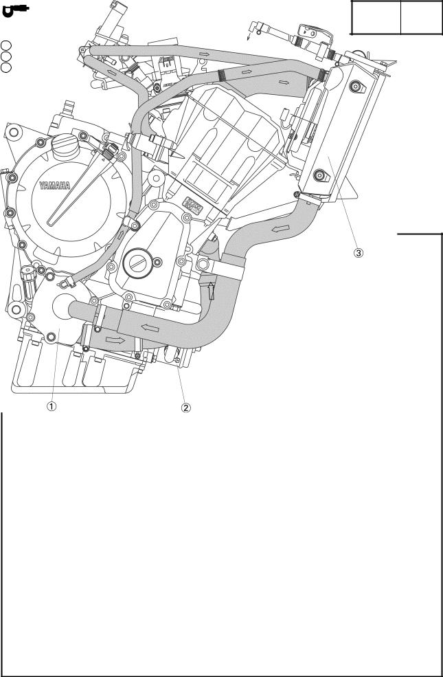
COOLING SYSTEM DIAGRAMS SPEC
1Water pump
2Oil cooler
3Radiator
–4–
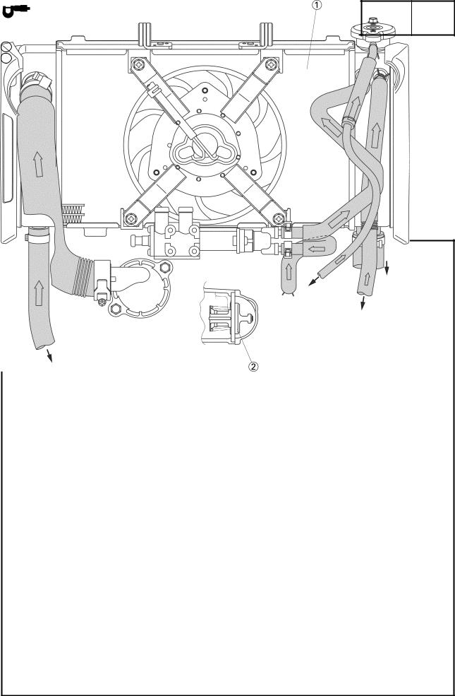
COOLING SYSTEM DIAGRAMS SPEC
1Radiator
2Thermostat
–5–
|
|
CABLE ROUTING |
|
SPEC |
|
CABLE ROUTING |
|
|
|
|
|
|
|
|
|
||
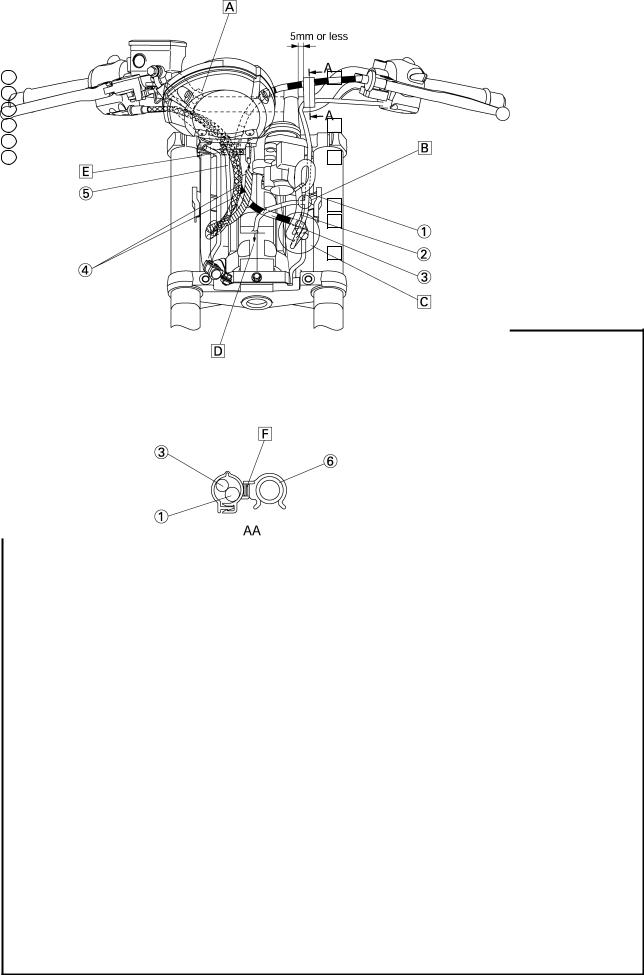
1 |
Left handlebar switch lead |
A Clamp the right handlebar switch lead and handle- |
|||
2 |
Main switch and immobilizer lead |
bar. Point the tip of the clamp downward in front of |
|||
3 |
Clutch cable |
the handlebar. |
|
|
|
4 |
Throttle cables |
B Route the branched lead behind the main switch |
|||
5 |
Right handlebar switch lead |
and immobilizer lead. |
|
|
|
6 |
Handlebar |
C Pass the main switch and immobilizer lead, left han- |
|||
|
|
dlebar switch lead and clutch cable in order through |
|||
the frame hole from the inner side of the vehicle. D To the headlight and speedometer.
E Pass the right handlebar switch lead and throttle cable, clutch cable through the meter cover hole.
F Install the clamp in the direction as shown in the illustration.
–6–
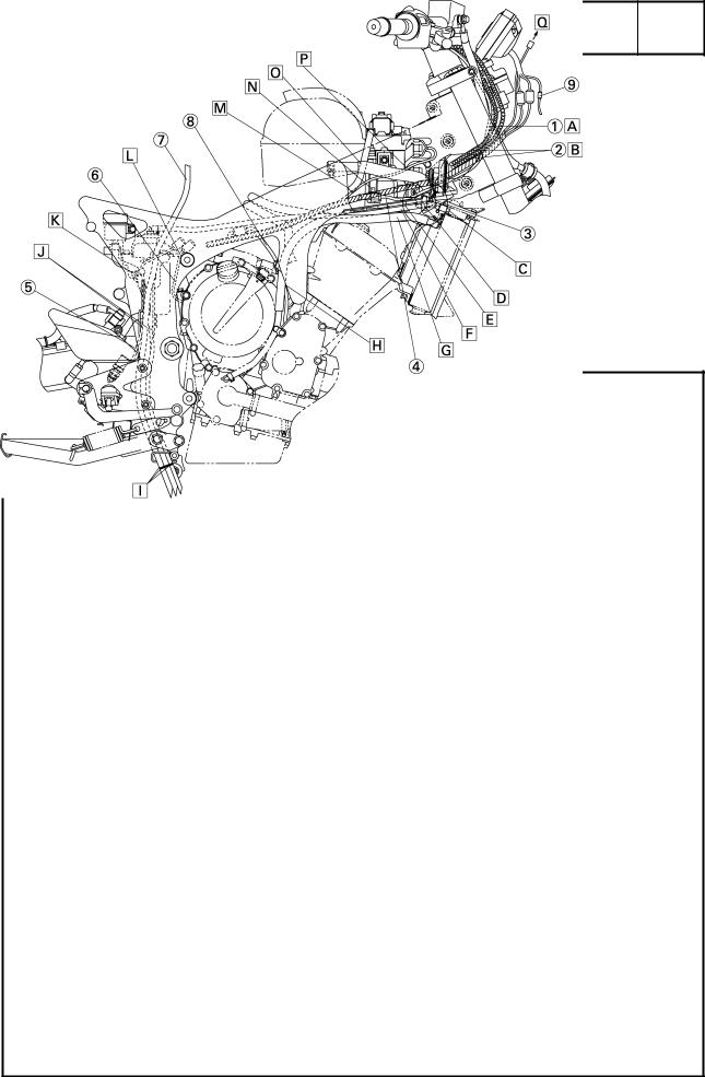
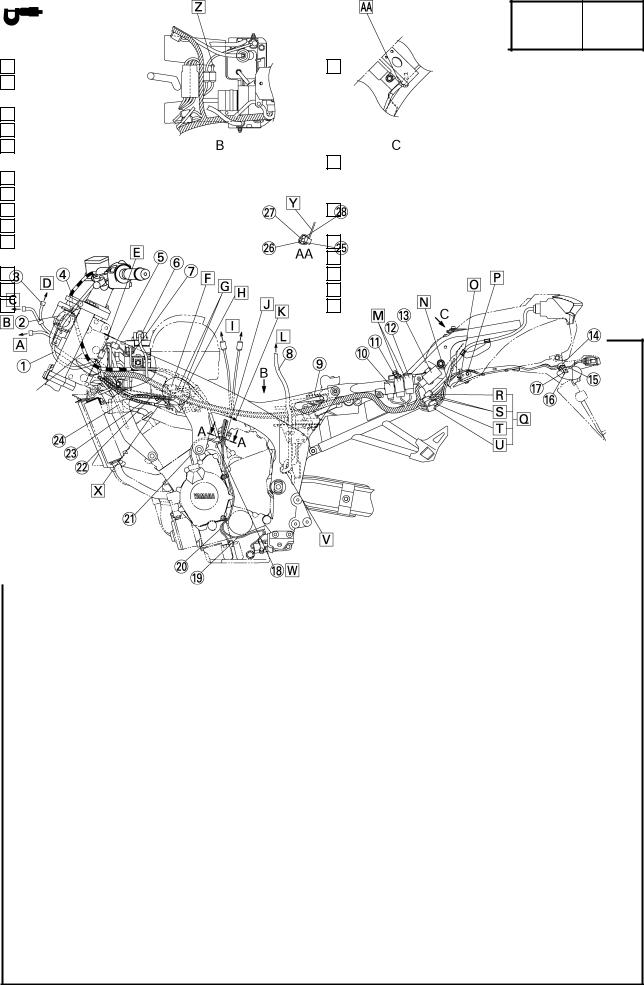
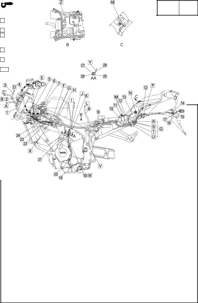
1Right handlebar switch lead
2Throttle cables
3Horn lead
4Wire harness
5Rear brake light switch lead
6Neutral switch lead
7Fuel tank breather hose
8Crankshaft position sensor lead
9Meter lead and left handlebar lead
APass the right handlebar switch lead through the hole on the right side of the frame.
Route it under the inside of the throttle cable and wire harness.
BPass the throttle cable through the hole located on the right side of the frame.
Route the throttle cable above the wire harness.
CABLE ROUTING SPEC
CRoute the horn lead inner side of the coolant reservoir tank hose.
DClamp the horn lead and radiator hose (the external side only). Horn lead should be positioned inside of the hose. Install the clamp in the direction pointing its detent pawl to the downside.
ERoute the right handlebar switch lead under the bracket 2.
FRoute the coolant reservoir tank hose under the cover 2. Route the radiator hose (outside) inner
side.
GRoute the radiator hoses (2 pieces) under the cover 2.
HRoute the crank shaft position sensor lead inner side of the radiator hose.
–7–
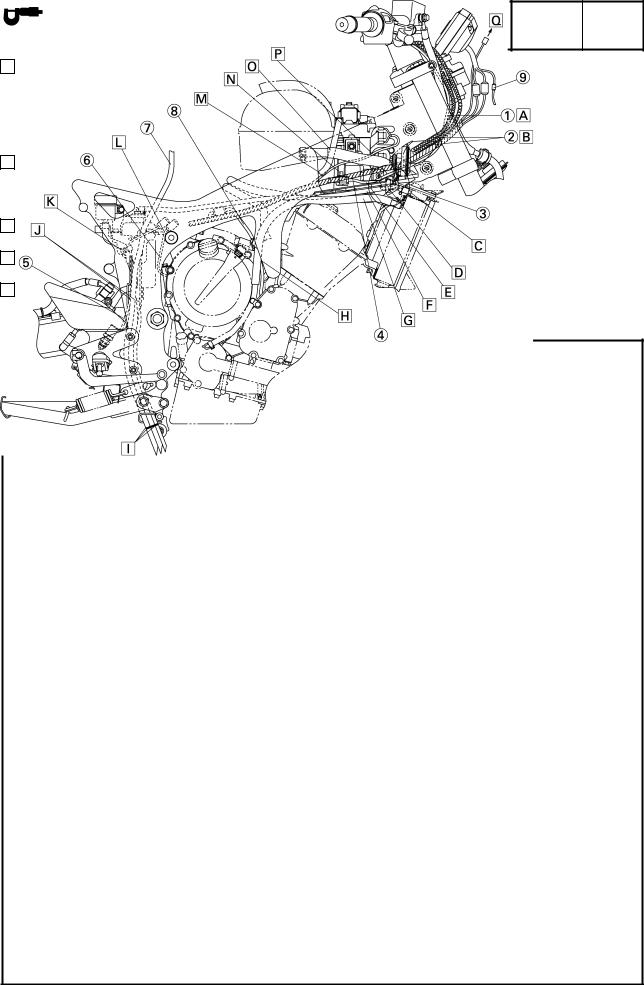
IPull down the mark-painted sections of the fuel tank breather hose, fuel tank drain hose and coolant reservoir tank breather hose to be lower than the clamp position of the muffler stay. Any order to take out the fuel tank breather hose and fuel tank drain hose can
be accepted.
JPass the fuel tank breather hose, fuel tank drain hose, coolant reservoir tank breather hose and
brake right switch lead through the guide of the stay assembly 2.
KClamp the tail brake light switch lead together with the brake fluid reservoir hose.
LPass the neutral switch lead between the engine and coolant reservoir tank bracket.
M To the starter motor.
CABLE ROUTING SPEC
N Install the right handlebar switch lead coupler through the hole of the bracket 2 from the downside.
O Route the starter motor lead by the inner side of the air cut-off valve hose.
P Pass the ignition coil leads #1 and #4 through inner side of the air cut-off valve hose, and then between the frame and bracket 2.
Q To the sub-wire harness.
–8–
|
|
|
CABLE ROUTING |
SPEC |
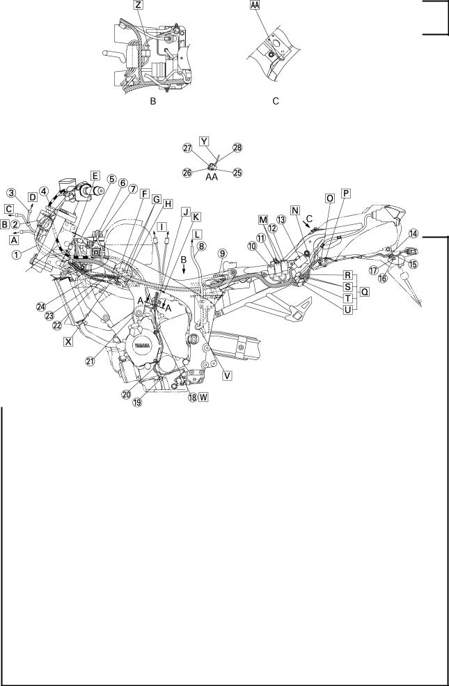
1 |
Left handlebar switch lead |
16 |
Rear turn signal light lead (right) |
|
2 |
Main switch and immobilizer lead |
17 |
Rear turn signal light lead (left) |
|
3 |
Meter lead and left handlebar switch lead |
18 |
Speed sensor lead |
|
4 |
Clutch cable |
19 |
Side stand switch lead |
|
5 |
Battery negative lead coupler |
20 |
Oil level switch lead |
|
6 |
Starter relay lead |
21 |
A.C. magneto lead |
|
7 |
Battery negative lead |
22 |
Throttle cable (return side) |
|
8 |
Fuel tank drain hose |
23 |
Throttle cable (pull side) |
|
9 |
Rectifier/regulator |
24 |
Radiator fan motor lead |
|
10 |
Turn signal relay |
25 |
Oil level gauge lead |
|
11 |
Radiator fan motor relay |
26 |
Sidestand switch lead |
|
12 |
Dimmer relay |
27 |
A. C. magneto lead |
|
13 |
Starting circuit cut-off relay |
28 |
Speed sensor lead |
|
14Clamp
15License plate light lead
–9–
ATo the headlight bulb.
BRoute it inside (in the width direction of the vehicle) of the left handlebar switch lead.
CTo the auxiliary light socket.
DTo the meter.
ELine up the left handlebar switch lead coupler and fan motor lead coupler behind the head pipe.
FTo the immobilizer.
GTo the main switch.
HPlace three couplers on the flange of the cover. I To the fuel pump.
J |
Clamp four wire leads. There should be no exces- |
|
sive slack on the wire leads. |
K |
To the engine. |
L |
To the fuel tank. |
M Either installation position can be accepted, but make sure that the leads are not crossed.
CABLE ROUTING SPEC
NClamp the rear turn signal lead and license plate light lead to the frame. Hook the clamp to the bracket. Pull out the lead sufficiently to the frame side and route it along with the side of the back stay. Cut the tip of the clamp to be between 1 and 5 mm (0.04 and 0.20 in) upward.
OClamp the rear turn signal lead and license plate light lead to the frame. Cut the tip of the clamp to be between 1 and 5 mm (0.04 and 0.20 in).
PGap between the lead and muffler should be 10 mm (0.39 in) or more.
QCoupler should not run on the relay assembly.
RTo the tail/brake light.
STo the license plate light.
T To the rear turn signal light. (right)
U To the rear turn signal light. (left)
–10–
CABLE ROUTING SPEC
VPass the fuel tank drain hose through the clamp located under the coolant reservoir tank.
W Route it behind the starter motor lead.
XPoint the bend-R section of the throttle cable (pull side) to the inner side horizontally. It is also possible to visually check the bend-R section.
YPoint the tip of the clamp to the inner side of the vehicle body.
ZMake sure to pass the neutral switch lead through the hole of the flap.
AAClamp the seat lock wire to the frame as shown in the illustration. Secure the clamp to the weld of the cross member with the frame. Position the binding section in front of the vehicle body and cut the tip to be between 1 and 5 mm (0.04 and 0.20 in).
–11–

|
|
|
CABLE ROUTING |
SPEC |
1 |
Right handlebar switch lead |
14 |
Seat lock cable |
|
2 |
Throttle cables |
15 |
Rectifier/regulator |
|
3 |
Battery positive lead |
16 |
E.C.U |
|
4 |
Coolant reservoir tank hose |
17 |
Fuel tank drain hose |
|
5 |
Battery cover |
18 |
Cover |
|
6 |
Connecter cover |
19 |
Starter relay lead |
|
7 |
Fuel tank breather hose |
20 |
Battery negative lead |
|
8 |
Brake fluid reservoir hose |
21 |
Battery negative lead coupler |
|
9 |
Lean angle cut-off switch |
22 |
Handlebar switch lead |
|
10 |
Fuse box |
23 |
Clutch cable |
|
11 |
Rear turn signal light lead (right) |
24 |
Cover 2 |
|
12 |
License plate light lead |
25 |
Spark plug lead |
|
13 |
Rear turn signal light lead (left) |
26 |
Air cut-off valve hose |
|
–12–
ATo the meter.
BEither right or left side arrangement for the left handlebar switch lead coupler and radiator fan motor coupler can be accepted.
CPoint the L-shape terminal to the front side of the vehicle.
DHook the starter motor lead to the alternate pawls on the battery cover.
ETo the crankshaft position sensor.
FRoute the crank shaft position sensor lead above
the starter motor leads.
GClamp the starter motor lead and crank shaft position sensor lead. Point the projected part of the tip to the inner side of the vehicle.
HPass the radiator hose, coolant reservoir hose, wire harness and starter motor lead in order through the lower side of the vehicle.
CABLE ROUTING SPEC
ISet the 4-pin coupler in the connector cover after wiring it.
J To the sidestand switch.
K To the speed sensor.
L To the A.C. magneto.
M To the oil level gauge.
NTo the rear brake/light switch.
OTo the neutral switch.
PPush the wire harness in the groove of the mud guard.
QPoint the opening section of the clamp upward.
RTo the rear turn signal. (right)
STo the rear turn signal. (left)
T To the license plate light.
UTo the tail/brake light.
VInsert the enwinding clamp of the wire harness into the hole of the rear frame.
–13–
|
|
|
CABLE ROUTING |
|
SPEC |
|
|
|
|
|
|
|
|
|
|
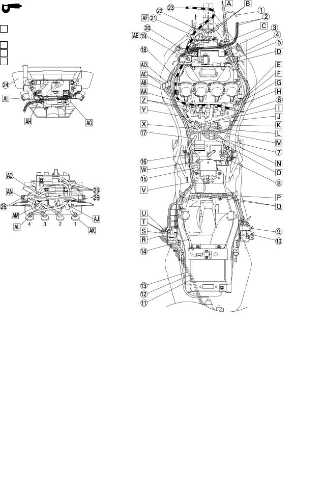
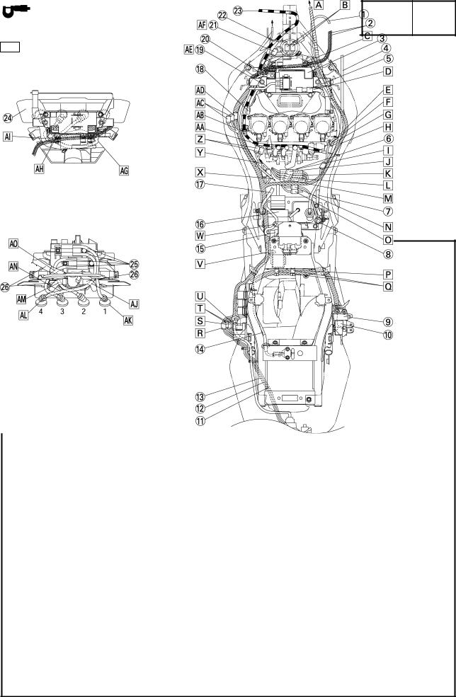
W Attach the rectifier regulator lead to the clamp of the |
|
Pass the spark plug leads #1 and #4 through the |
|||||
AG |
|||||||
|
rectifier bracket. |
|
slit of the cover 2. |
|
|
|
|
X To the engine ground. |
AH |
Pass the spark plug lead #2 through the inner |
|||||
Y |
To the fuel injection. |
|
hole of the cover 2. |
|
|
|
|
Z |
To the fuel pump. |
AI |
Pass the spark plug lead #3 through the outer |
||||
|
Route the clutch cable under the fuel injection |
|
hole of the cover 2. |
|
|
|
|
AA |
|
|
|
|
|||
|
|
lead. |
|
Route the spark plug lead #4 behind the air cut-off |
|||
|
|
AJ |
|||||
|
Pass the clutch cables through the clamp, and |
|
valve hose. |
|
|
|
|
AB |
|
|
|
|
|||
|
|
then install the clamp to the cover. Position of the |
|
Point the spark plug caps of #1 to #4 to the direc- |
|||
|
|
AK |
|||||
|
|
clamp is forward of the cable stopper. |
|
tion as shown in the illustration. |
|||
|
To the main switch. |
|
Route the spark plug lead #3 under the air cut-off |
||||
AC |
AL |
||||||
|
To the immobilizer. |
|
valve hose. |
|
|
|
|
AD |
|
|
|
|
|||
|
Route the starter relay lead outside of the main |
|
Route the spark plug lead #2 behind the air cut-off |
||||
AE |
AM |
||||||
|
|
switch and immobilizer lead. |
|
valve hose. |
|
|
|
AF |
Press the battery negative lead into the space be- |
AN |
Route the spark plug lead #4 by the front side of |
||||
|
|
tween the ribs of the frame. |
|
the spark plug leads #2 and #3. |
|||
|
|
|
|
|
|
|
|
|
|
|
|
|
|
|
|
–14–
CABLE ROUTING SPEC
AO Route the spark plug leads #2 and #3 behind the air cut-off valve hose.
–15–
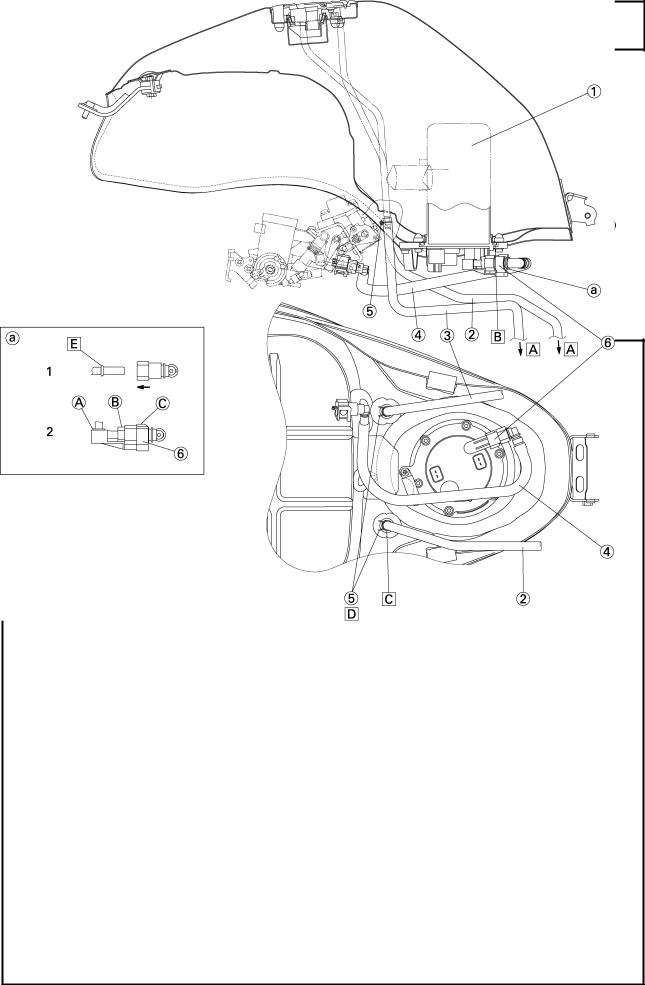
1Fuel pump assembly
2Fuel tank breather hose
3Fuel tank drain hose
4Fuel hose
5Clip
6Clamp
AAir opening.
BInstall the O-ring with its lip pointed upward.
CFuel tank breather hose has a white point mark.
DPoint the knob of clip front side
CABLE ROUTING SPEC
aFuel piping connector attachment directions. (fuel pump side)
1.It is inserted until it makes a click sound the connector, and it checks that a connector does not fall out. It takes care that a foreign substance does not enter
into a seal portion. (Working groves should not be used at the time of work.)
E It prevents that this portion falls out.
2.The clamp is attached from the bottom after the work of “1”.
It checks being completely equipped with A , B and C section.
–16–
 Loading...