


 Loading...
Yamaha DZR12-D, DZR10, DZR315-D, DZR315, DZR15-D User Manual
...POWERED LOUDSPEAKER |
|
|
POWERED SUBWOOFER |
|
|
|||
|
|
|
|
|
|
|
|
|
|
|
|
|
|
|
|
|
|
|
|
|
|
|
|
|
|
|
|
|
|
|
|
|
|
|
|
|
|
|
|
|
|
|
|
|
Reference Manual
ENJA

Contents
Introduction |
|
|
|
3 |
DZR(-D), DXS-XLF(-D) Series Product Lineup |
.................................................... 3 |
|||
Main Features ...................................................................................................... |
|
|
3 |
|
Main Functions .................................................................................................... |
|
|
4 |
|
Structure of Manuals............................................................................................ |
|
4 |
||
Functions |
|
|
|
5 |
Full-range Speaker (Rear) ................................................................................... |
5 |
|||
Subwoofer (Rear)................................................................................................. |
|
|
5 |
|
Rear Panel |
Full range |
Subwoofer ............................................................... |
6 |
|
Power Section |
.............................................................................................. |
|
7 |
|
Dante Section |
Dante model ...................................................................... |
8 |
||
Panel Operations |
|
9 |
||
Basic Operations ................................................................................................. |
|
|
9 |
|
HOME Screen and Its Functions ....................................................................... |
10 |
|||
Alert Messages.................................................................................................. |
|
|
12 |
|
Initialization ........................................................................................................ |
|
|
|
12 |
Screen Functions |
|
13 |
||
Screen Structure................................................................................................ |
|
|
13 |
|
PRESET Screen ................................................................................................. |
|
|
13 |
|
RECALL...................................................................................................... |
|
|
|
14 |
STORE........................................................................................................ |
|
|
|
14 |
CLEAR........................................................................................................ |
|
|
|
14 |
TITLE .......................................................................................................... |
|
|
|
14 |
PROTECT ................................................................................................... |
|
|
15 |
|
HPF Screen |
Full range ................................................................................. |
15 |
||
LPF Screen |
Subwoofer ................................................................................ |
15 |
||
D-CONTOUR Screen |
Full range .................................................................. |
15 |
||
D-XSUB Screen |
Subwoofer ......................................................................... |
16 |
||
EQ Screen ......................................................................................................... |
|
|
|
16 |
DELAY Screen ................................................................................................... |
|
|
16 |
|
CARDIOID Screen |
Subwoofer ..................................................................... |
17 |
|
ROUTER Screen................................................................................................ |
|
18 |
|
UTILITY Screen |
................................................................................................. |
|
19 |
PANEL SETUP............................................................................................ |
|
19 |
|
PANEL LOCK ............................................................................................. |
|
20 |
|
DEVICE BACKUP....................................................................................... |
23 |
||
DANTE SETUP ................................................................... |
Dante model |
23 |
|
NETWORK ......................................................................... |
Dante model |
25 |
|
DEVICE INFORMATION ............................................................................. |
26 |
||
INITIALIZE.................................................................................................. |
|
|
26 |
LOG ........................................................................................................... |
|
|
27 |
UPDATE FIRMWARE .................................................................................. |
27 |
||
Muting from an External .............................................Device Dante model |
28 |
||
About Dante |
Dante model |
29 |
|
Dante Network System ...................................................................................... |
29 |
||
Dante Settings ................................................................................................... |
|
|
30 |
Connecting to Dante ...........................................................................Devices |
30 |
||
Integration with .............................................................Yamaha Digital Mixers |
31 |
||
Reference |
|
|
33 |
Precautions when .......................................................Using the USB Terminal |
33 |
||
Using USB Flash ....................................................................................Drives |
33 |
||
Function Tree ..................................................................................................... |
|
|
34 |
Message List ..................................................................................................... |
|
|
37 |
Patch Correspondence .................................Chart when Using Quick Config |
39 |
||
Troubleshooting ................................................................................................. |
|
|
40 |
Dante-related Terms .......................................................................................... |
|
41 |
|
Specifications .................................................................................................... |
|
|
42 |
Dimensions........................................................................................................ |
|
|
46 |
Block Diagram................................................................................................... |
|
|
52 |
Index.................................................................................................................. |
|
|
53 |
2

Introduction
Thank you for purchasing the Yamaha DZR(-D) series POWERED LOUDSPEAKER and DXS-XLF(-D) series POWERED SUBWOOFER. (See the series product lineup below.) These products are designed for live performance, sound reinforcement and fixed installation sound system applications. This manual provides instructions on installation, setup, configuring of the connections, and detailed operation of these speakers for installers, constructors, or general users familiar with speakers. Please read this manual together with the Owner’s Manual that comes packaged with the product to get full use out of this product and its functions.
*Unless specifically noted otherwise, illustrations in this manual are based on the DZR12-D and DXS18XLF-D.
*In this manual the Dante model (-D) series is referred to as DZR-D, DXS-XLF-D.
DZR(-D), DXS-XLF(-D) Series Product Lineup
Type |
Standard Model |
Dante Model (-D) |
||
|
3-way 15" |
DZR315 |
DZR315-D |
|
Full Range |
2-way 15" |
DZR15 |
DZR15-D |
|
2-way 12" |
DZR12 |
DZR12-D |
||
|
||||
|
2-way 10" |
DZR10 |
DZR10-D |
|
Subwoofer |
18" |
DXS18XLF |
DXS18XLF-D |
|
15" |
DXS15XLF |
DXS15XLF-D |
||
|
||||
|
|
|
|
|
Main Features
•Strong plywood cabinet features a high output Class D amplifier. Full-range models feature powerful sound pressure capability in a lightweight package by using neodymium magnets.
•Optimized pairing of a highly durable speaker unit with a fixed directional horn, for sparkling highs with punchy and powerful bass.
•Full-range models feature an FIR filter for crossover and frequency adjustments. Low latency for DSP and AD/DA, thanks to 96 kHz sampling rate.
•LCD screen for loading presets, and for making precise graphical adjustments to EQ, delay, and routings. Easily transfer settings by using a USB flash drive.
•Dante models (-D) support the transmission of digital audio and remote control via a Dante network.
•2-way models support use on a stand or use as a floor monitor. Rotation of the horn, several rigging points, and optional brackets allow a variety of installation methods.
3

Introduction
Main Functions
Processing
Incorporates new FIR filter technology in addition to signal processing know-how built up through years of product development experience in order to deliver the next level in sound quality. The DSP, AD/DA sampling frequency (Fs) is 96 kHz.
Display  See page 6
The display enables users to set a broad range of functions using simple commands while finely tuning EQ, delay, routing and other settings using a graphical interface. Includes a back light for adjusting luminance.
Presets  See pages 11, 13
A set of recall-only factory presets (one to three) and savable user presets (eight) are available. Select the desired preset from the factory presets when using the DZR and DXS-XLF series product together.
Network  See pages 8, 29
Dante-compatible models not only allow for audio input/output across a Dante network, they also enable users to control and monitor this product on a computer, etc.
Integration with Yamaha digital mixers  See page 31
Connect a Dante-compatible model with a TF series, CL series or QL series device over a network to monitor patching and device status without a Dante Controller. Yamaha provides a unique system solution centered around its digital mixers.
Other useful functions
•Safeguard functions are in place to prevent malfunction. Alert messages and other notifications are used to inform users when an issue occurs.  See page 12
•Comes equipped with a panel lock feature preventing operational errors and tampering. Connect a USB flash drive with the PIN code saved to it to temporarily unlock the panel. Remove the stick to lock the panel again.  See page 20
•Internal data can be stored on a USB flash drive, making it easy to copy the same settings to a replacement device.  See page 23
Structure of Manuals
•Owner’s Manual (included with the product)
This manual describes product functions and basic product operation.
•Reference Manual (this manual)
This manual describes settings and operations in detail.
4
Functions
Full-range Speaker (Rear)
w e
Bottom
q
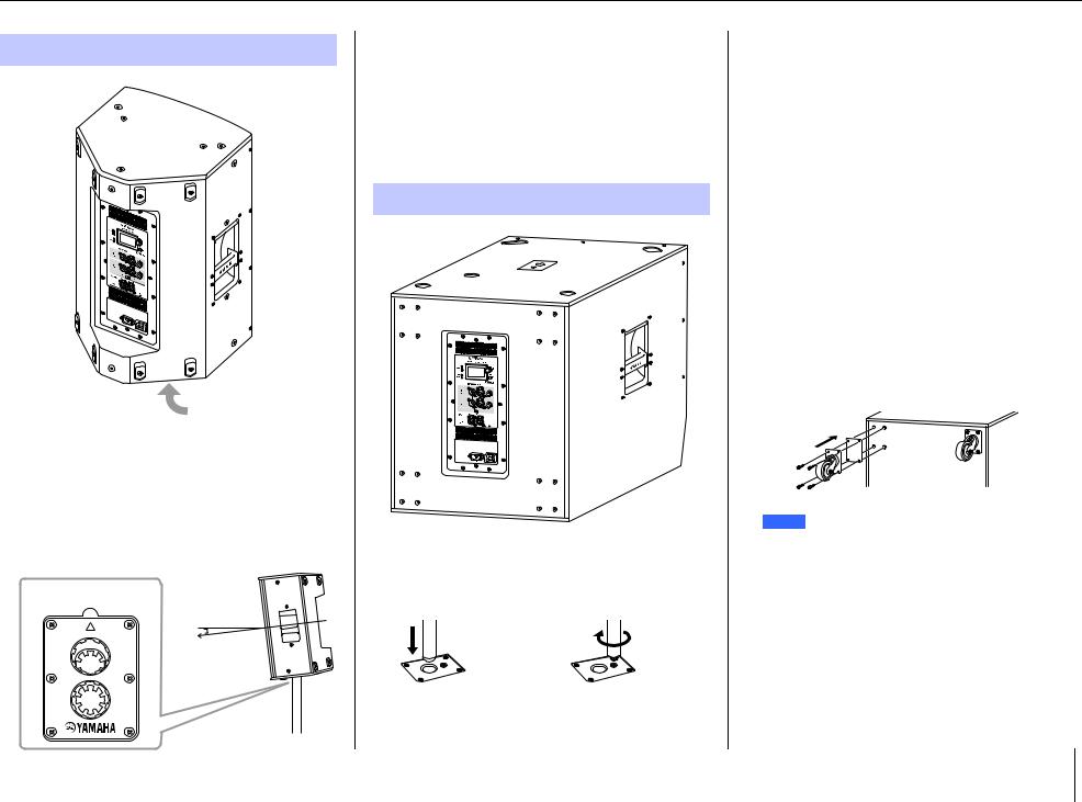
qTiltable pole socket
This mount has two pole sockets. You can choose the angle of the speaker so that it is positioned horizontal to the floor or tilting down toward the floor by 7 degrees. Compatible with commercially available speaker stands and speaker poles of 35 mm diameter. (These sockets are not available on the DZR315(-D).)
Pole socket
FRONT |
7° |
7°
0°
wScrew holes for U-bracket
For installing with the separately sold U-brackets. (These sockets are not available on the DZR315(-D).)
eScrew holes for eye bolts
For installing the speaker using eye bolts. The screw holes for eye bolts go through the cabinet wall.
Subwoofer (Rear)
r
 t
t
y
rDual pole sockets
Compatible with commercially available speaker poles of 35 mm diameter and M20 screw.
35 mm |
M20 screw |
diameter |
|
When using a pole socket to install a speaker, observe the following conditions for safety.
Subwoofer |
Speaker to be installed |
Length of |
|
the pole |
|||
|
|
||
|
Weight: 26 kg or less |
|
|
DXS18XLF(-D) |
Height: 76.0 cm or less |
104 cm or less |
|
|
(DZR15(-D) or smaller) |
|
|
|
Weight: 22 kg or less |
|
|
|
Height: 64.5 cm or less |
82 cm or less |
|
DXS15XLF(-D) |
(DZR12(-D) or smaller) |
|
|
|
|
||
Weight: 18 kg or less |
|
||
|
|
||
|
Height: 53.7 cm or less |
104 cm or less |
|
|
(DZR10(-D) or smaller) |
|
|
|
|
|
tFeet cups
When stacking multiple speakers, align the rubber feet of the upper speaker to the feet cups of the lower one.
yWheel mounting screws
For installing the separately sold Yamaha SPW-1 wheels. If you are not using wheels, do not remove these screws. Otherwise, the leakage of air will affect sound quality.
NOTE
•For more information about installing wheels and related precautions, refer to the corresponding manual for the wheels.
•Do not install any item other than the SPW-1 wheels.
5

Rear Panel
Full range 
 Subwoofer
q |
w |
e |
o
 !1
!1
r t
y
i
u |
!0
!1 |
Available only on Dante models. See the “Dante Section” (page 8).
qUSB terminal
Connect a USB flash drive to save/load internal memory on this product. USB flash drives are also used to perform firmware updates. You can also save a PIN code used to lock the panel to a USB flash drive, and then connect the USB flash drive to temporarily unlock the panel.
For more information about using the USB terminal and USB flash drives, see “Precautions when Using the USB Terminal” and “Using USB Flash Drives” (page 33).
w[LIMIT] indicator
Lights red when the limiter for protecting the speaker is active. If the indicator remains on, lower the level of the input signal. This flashes together with the e [POWER] indicator when a serious system error is detected at product startup. This indicator will turn off automatically when BLACKOUT is ON (see page 20).
e[POWER] indicator
Lights green when the power is on. Flashes when the protection function is active and the output is muted. (“MUTED” appears on the HOME screen in the display at this time.) This flashes together with the w [LIMIT] indicator when a serious system error is detected at product startup.
NOTE
The [POWER] indicator will not automatically turn off even if BLACKOUT (page 20) is ON.
Functions
rDisplay
Shows the settings for various functions. Users can finely tune EQ, delay, routing and other settings using a graphical interface. The display includes a back light, enabling users to adjust the brightness and contrast of the display, configure BLACKOUT (automatic off) settings (see page 20).
NOTE
•The display will darken after one minute of panel inactivity and turn off after 25 minutes of inactivity to protect the display, even if the BLACKOUT (page 20) setting is off. Either press a key on the rear panel or press the main knob to wake the display.
•The display will start flashing when the Identify function is used on a Dante Controller or Dante devices (each of the TF, CL, and QL series, etc.).
tMain knob
Turn the knob to move the cursor that appears in the display and change parameter values. Press the knob to execute a setting.
y[ ] (Back) key
Press this button to return to the previous screen. Press and hold this button for at least one second to return to the HOME screen.
u[LEVEL] controls
Adjust the level that is input to the [INPUT] jacks.
6

i[INPUT] jacks
Combo jacks for line level input. Accept both XLR and phone plugs. This enables you to mix levels for two input signals separately. Not compatible with mic input.
o[THRU/OUTPUT] jacks
XLR output jacks. Switch the DZR(-D) series channel 2 and DXS-XLF(-D) series channel 1 and 2 output signals using the !0 [THRU/DSP OUT] switch. The DZR(- D) series channel 1 output is fixed to [THRU].
DZR(-D) Series |
DXS-XLF(-D) Series |
||||||
|
|
|
|
|
|
|
|
|
|
|
|
|
|
|
|
|
|
|
|
|
|
|
|
|
|
|
|
|
|
|
|
|
|
|
|
|
|
|
|
|
|
|
|
|
|
|
|
!0[THRU/DSP OUT] switch
This switch determines whether signals output from the output jack are passed through the input jack as is ([THRU]), or whether the signal receives DSP processing before input ([DSP OUT]). When this is set to [DSP OUT], you can set the output signal. For more information about signals that can be output, see “ROUTER Screen” – “e OUTPUT” (page 19).
!1Vents
A cooling fan is installed on the exhaust side. The fan will start once the amp exceeds a certain temperature. Fan speed is controlled based on the temperature of the amp and power source. When the speaker is in use, make sure that all of the vents are free from obstruction.
Power Section
!2 !3
!2[AC IN] jack
Connect the supplied AC power cord here. First, connect the power cord to this product, then insert the power cord plug into the AC outlet. When removing the power cord, perform this procedure in reverse order. While the internal power supply functions within the 100V – 240V range, the limiter may not work properly if a different voltage to that shown is used, since the maximum output and limiter setting are optimized according to the voltage used. Do not use a voltage setting other than that shown.
WARNING
Use only the supplied power cord/plug.
CAUTION
Be sure to turn the power off before connecting or disconnecting the power cord.
Insert the power cord fully until it is locked by the latching lock mechanism (V-Lock).
Press the V-Lock latch to disconnect the power cord.
Functions
!3Power switch
Turns the power supply on [–] or off [ ].
].
WARNING
A small amount of current flows even when the power switch is off. If you intend to not use the speaker for a long time, be sure to unplug the power cord from the outlet.
NOTE
•Depending on the timing when the power switch is turned on/off, it might take up to 15 seconds for the power to turn on.
•When using multiple devices, we recommend turning each device on one at a time. If multiple devices are turned on at the same time, the devices might not start up correctly due to a voltage drop at the power supply.
7
Dante Section
Dante model
!5 !6!5 !6
!4 

 !4
!4 


 !7
!7
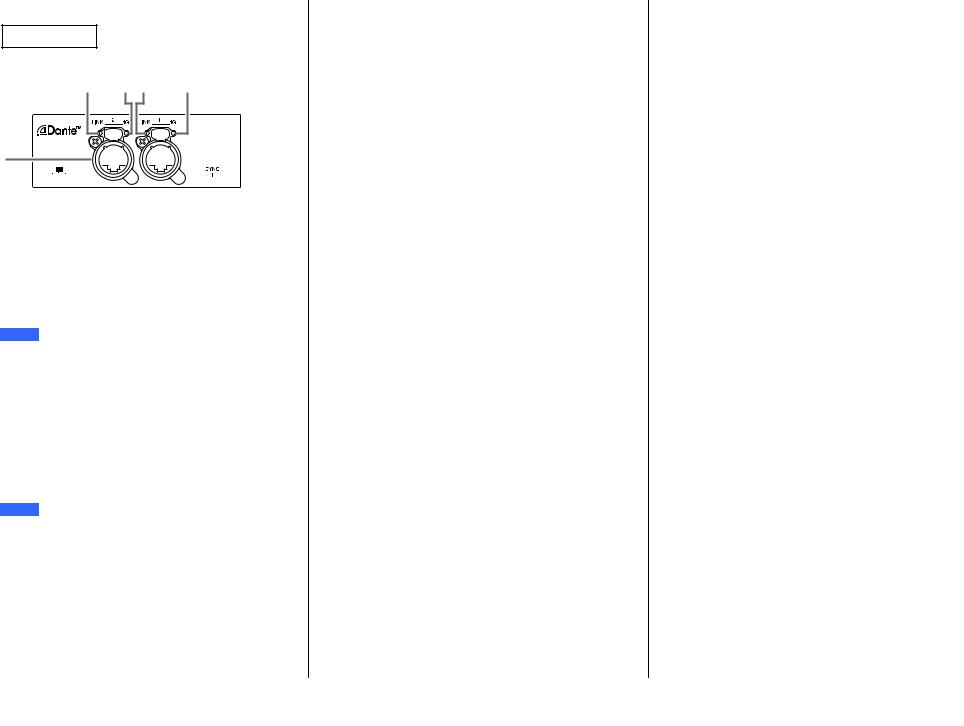
!4Dante jacks
These are etherCON jacks for connecting with Dante devices and computers. The two jacks are primary connectors that can be linked in a daisy chain connection (see page 29). This connection cannot be used in a redundant (secondary) network.
NOTE
Use STP (Shielded Twisted Pair) cables to prevent electromagnetic interference. Make sure that the metal parts of the plugs are electrically connected to the STP cable shield by conductive tape or comparable means.
!5[LINK] indicator
Shows the communication status of Dante jacks. Lights green when an Ethernet cable is connected correctly to the Dante jack. This indicator will turn off automatically when BLACKOUT is ON (see page 20).
NOTE
This indicator may flash for 30 seconds when the power is turned on when connected to a network device.
!6[1G] indicator
This indicator will light up in orange when the Dante network is functioning as a Giga-bit Ethernet.
This indicator will turn off automatically when BLACKOUT is ON (see page 20).
Functions
!7[SYNC] indicator
Lights steady or flashes green according to the Dante communication status, as shown in the following table. This indicator will turn off automatically when BLACKOUT is ON (see page 20).
Steady |
Operating normally as a clock |
|
slave on the Dante network |
||
|
||
Continuously flashes |
Operating normally as a clock |
|
master on the Dante network |
||
|
||
Periodically flashes |
Incorrect DANTE Fs setting |
|
one time |
||
|
||
Periodically flashes |
Dante network cable not con- |
|
two times |
nected |
|
Periodically flashes |
Incorrect Dante network con- |
|
three times |
nection |
|
|
|
8
Panel Operations
Basic Operations
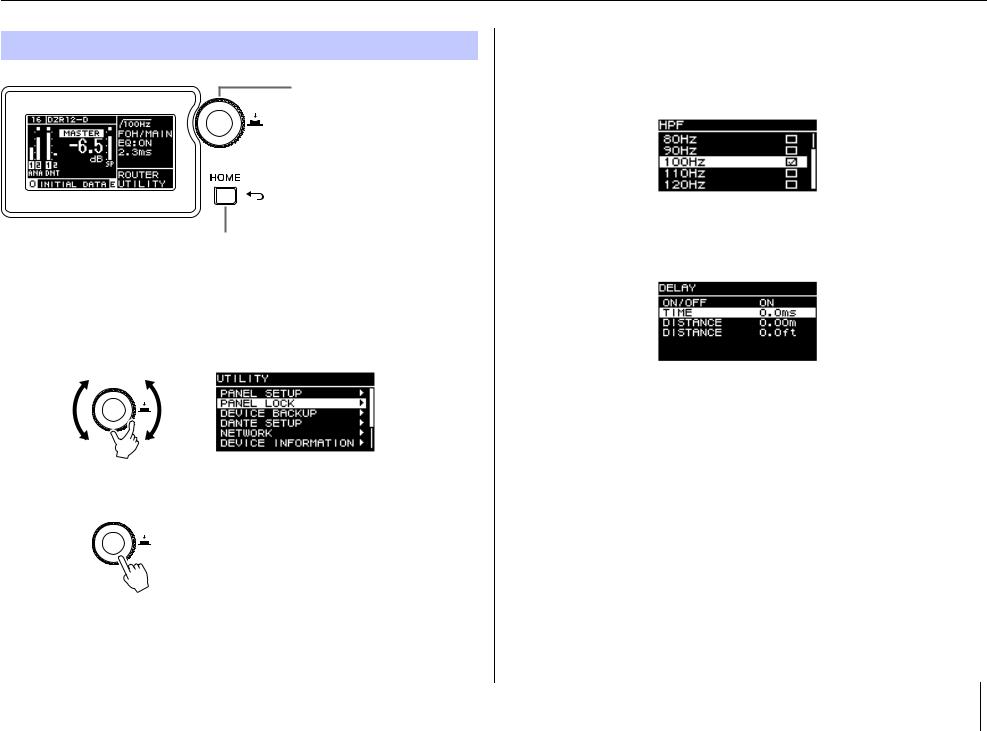
Main knob
The main knob is used to move the cursor and adjust parameter values. Parameters with a broad range of values can be adjusted more quickly based on the speed at which the main knob is turned.
[ ] (Back) key
Press this key to move up one level from the current level, or to return to the previous screen. Press and hold this button for at least one second to return to the HOME screen.
1. Turn the main knob to select an item. The selected item is highlighted.
The > on the right indicates that there are deeper menu items.
2. Press the main knob to execute a selection.
3. Repeat steps 1 and 2 until you reach the edit parameter screen.
Edit selectable parameters
Turn the main knob to select. The value will be updated and the sound will change when you press the main knob to execute the change.
Edit continuous parameters
Turn the main knob to change the parameter value. The value is changed in real time as you turn the knob.
4. For selectable parameters, press the main knob to execute the edited value.
Press the [ ] (Back) key to return to the previous screen (press and hold for at least one second to return to the HOME screen).
9

Panel Operations
HOME Screen and Its Functions
The HOME screen will appear when the power switch is turned on. Refer to the HOME screen for the model in use.
Dante model
DZR-D series
|
|
|
|
|
q |
r t |
|||||||||||||
|
|
|
|
|
|
|
|
|
|
|
|
|
|
|
|
|
i |
||
|
|
|
|
|
|
|
|
|
|
|
|
|
|
|
|
|
|||
|
|
|
|
|
|
|
|
|
|
|
|
|
|
|
|
|
|||
w |
|
|
|
|
|
|
|
|
|
|
|
|
|
|
|
|
o |
||
|
|
|
|
|
|
|
|
|
|
|
|
|
|
|
|
||||
|
|
|
|
|
|
|
|
|
|
|
|
|
! |
||||||
|
|
|
|
|
|
|
|
|
|
|
|
||||||||
e |
|
|
|
|
|
|
|
|
|
||||||||||
|
|
|
|
! |
|||||||||||||||
|
|
|
|||||||||||||||||
|
|
|
|
|
|
|
|
|
|
! |
|||||||||
|
|
|
|
|
|
|
|
|
|||||||||||
|
|
|
|
|
|
|
|
|
|
|
! |
||||||||
|
|
|
|
|
|
|
|
|
|||||||||||
|
|
|
|
|
|
|
|
|
|||||||||||
|
|
|
|
|
|
|
|
|
|||||||||||
|
|
|
|
u |
|
y |
|||||||||||||
DXS-XLF-D series |
|
|
|
|
|
|
|
|
|
|
|
|
|||||||
|
|
|
|
|
q |
r t |
|||||||||||||
|
|
|
|
|
|
|
|
|
|
|
|
|
|
|
|
|
i |
||
|
|
|
|
|
|
|
|
|
|
|
|
|
|
|
|
|
|||
|
|
|
|
|
|
|
|
|
|
|
|
|
|
|
|
|
|||
w |
|
|
|
|
|
|
|
|
|
|
|
|
|
|
|
|
o |
||
|
|
|
|
|
|
|
|
|
|
|
|
|
|
|
|
||||
|
|
|
|
|
|
|
|
|
|
|
|
|
|
! |
|||||
e |
|
|
|
|
|
|
|
|
|
|
|
|
|
|
|
|
|||
|
|
|
|
|
|
|
|
|
|
! |
|||||||||
|
|
|
|
|
|
|
|
|
|||||||||||
|
|
|
|
|
|
|
|
|
|
|
! |
||||||||
|
|
|
|
|
|
|
|
|
|||||||||||
|
|
|
|
|
|
|
|
|
|
|
|
|
|
|
! |
||||
|
|
|
|
|
|
|
|
|
|
|
|||||||||
|
|
|
|
|
|
|
|
|
|
|
|
|
|
! |
|||||
|
|
|
|
|
|
|
|
|
|
||||||||||
|
|
|
|
|
|
|
|
|
|
|
|
||||||||
|
|
|
|
|
|
|
|
|
|
|
|||||||||
|
|
|
|
u |
|
y |
|||||||||||||
NOTE
Standard model
DZR series
r t
i
o w
 !
!
!
!
!
u y
DXS-XLF series
r t
i
o w
 !
!
!
!
!
!
u y
•Even while displaying other than the HOME screen, if you do not operate the panel for 5 minutes, the screen automatically returns to the HOME screen.
•The above screens of the Dante models are examples when setting LABEL of q to "DZR12-D" and "DXS18XLF-D," respectively.
10
qUNIT ID, LABEL Dante model
Shows the UNIT ID and label assigned so that DZR-D or DXS-XLF-D series devices on the Dante network can be recognized. When the DANTE MODE (page 23) is set to Quick Config, this will show as “QC,” and the name of the selected TF series output channel. Go to the DANTE SETUP screen to configure and display Dante settings.
wInput Meter
Shows analog input signal levels. On Dante models this will appear as ANA. Clipped input signals will light up at the top when clipping occurs.
eInput Meter (DNT) Dante model
Shows digital input signal (Dante) levels. Clipped input signals will light up at the top when clipping occurs.
rMASTER Level
Sets and displays output levels. (Unit: dB)
tSP Output Meter
Shows output levels. Sigma ( ) clipping at the top will light up when clipping occurs within a channel.
yProtection (THERMAL, MUTED)
Appears when safeguard functions have been activated. “THERMAL” is shown when a high temperature is detected in the amplifier, and output levels are reduced. If operating conditions further deteriorate, this will change to “MUTED,” and the output signal will be muted.
uPRESET
Shows the preset number and title of the set preset. This enables you to save, load and change audio settings.  (E symbol) will appear when parameters have been changed.
iHPF Full range
Sets and displays the high-pass filter frequency.
LPF Subwoofer
Sets and displays the low-pass filter frequency and the POLARITY. An indication Ø will appear when POLARITY is set to INVERTED.
Panel Operations
oD-CONTOUR Full range
Sets and display the D-CONTOUR mode.
D-XSUB Subwoofer
Sets and displays the D-XSUB mode.
!0EQ
Shows whether the equalizer (6 Band EQ) is on or off. You can configure EQ settings while checking the frequency response characteristics.
!1DELAY
Sets and displays the delay.
!2CARDIOID Subwoofer
Sets and displays the cardioid mode.
!3ROUTER
Configures the routing of the audio signal.
!4UTILITY
Sets and displays the device operating settings.
•PANEL SETUP: Sets the brightness and contrast of the display, and automatic turn off settings for the display and indicators.
•PANEL LOCK: Configures panel lock settings, and saves and loads PIN codes.
•DEVICE BACKUP: Saves and loads settings data.
• DANTE SETUP Dante model : Sets and displays Dante-related settings.
• NETWORK Dante model : Sets and displays network-related settings.
•DEVICE INFORMATION: Shows device status, and device-specific information.
•INITIALIZE: Resets to the default settings.
•LOG: Shows recorded logs and saves logs to a USB flash drive.
•UPDATE FIRMWARE: Updates the firmware for the device, and the Dante module.
11
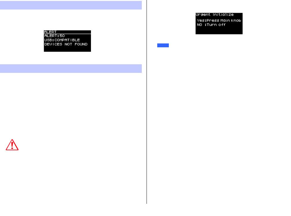
Alert Messages
When an error occurs, an alert message will appear on the display.
For more details on each error message and notification, see the “Message List” (page 37).
E.g.)
Initialization
You can reset to the default settings for this product in the following two ways.
Initializing to the default settings by navigating from the HOME screen and selecting UTILITY → INITIALIZE
(See page 26.)
Initializing to the default settings when you have forgotten your PIN code, etc.
Use the following method to reset to the default settings if you are unable to select INITIALIZE on the UTILITY screen because of a forgotten PIN code, etc.
1. Disconnect all the cables except the power cord.
WARNING
A sudden loud sound might occur when initializing is completed, if an audio signal is present.
2. Turn the power switch off.
3. After the [POWER] indicator turns off, turn the power switch back on.
4. While pressing and holding the main knob, turn the main knob at least five clicks in a counter-clockwise direction within two seconds of the [POWER] indicator light coming on. (Keep pressing and holding the main knob.)
If the procedure is not finished properly in time, the model name logo will appear. In this case, repeat the procedure again from step 2.
Panel Operations
5. When the [POWER] indicator starts flashing and the screen shown below appears, release the main knob.
NOTE
To cancel the initialization process at this point, turn the power switch off.
6. Press the main knob.
This product will be restarted automatically.
7. Wait until the HOME screen appears.
NOTICE
Turning the power switch off before the HOME screen appears could cause a malfunction.
12

Screen Functions
Screen Structure
Turn the main knob to move the cursor to the desired menu item and select it to move to the corresponding screen.
To the HPF screen Full range (page 15)
To the LPF screen Subwoofer (page 15)
To the DANTE SETUP screen Dante model (page 23)
To the PRESET screen (page 13)
To the D-CONTOUR screen
Full range (page 15)
To the D-XSUB screen
Subwoofer (page 16)
To the EQ screen (page 16)
To the DELAY screen (page 16)

 To the CARDIOID screen Subwoofer (page 17)
 To the ROUTER screen (page 18) To the UTILITY screen (page 19)
PRESET Screen
As presets which is sound related setting, allows you to recall/store/clear the settings, edit titles, and set the protection of the settings. The recall-only presets are always protected. An  (E symbol) (page 11) will appear on the HOME screen when parameters have been changed.
Full range |
(factory default settings) |
|
|
|
|
|
|
|||||||||||
Key mark |
: |
|
|
|
|
|
|
|
|
|
|
|
|
|
|
|
|
|
Indicates a protected pre- |
|
|
|
|
|
|
|
|
|
|
|
|
|
|
q |
|||
|
|
|
|
|
||||||||||||||
set |
|
|
|
|
|
|
|
|
|
|
|
|
|
|
|
|
|
w |
|
|
|
|
|
|
|
|
|
|
|
|
|
|
|
|
|
||
: Indicates the currently |
|
|
|
|
|
|
|
|
|
|
|
|
|
|
e |
|||
selected preset |
|
|
|
|
|
|||||||||||||
|
|
|
|
|
|
|||||||||||||
|
|
(factory default settings) |
|
|
|
|
|
|
||||||||||
Subwoofer |
|
|
|
|
|
|
|
|||||||||||
|
|
|
|
|
|
|
|
|
|
|
|
|
|
q |
||||
|
|
|
|
|
|
|
|
|
|
|
|
|
|
|||||
|
|
|
|
|
|
|
|
|
|
|
|
|
|
|||||
|
|
|
|
|
|
|
|
|
|
|
|
|
|
|
w |
|||
|
|
|
|
|
|
|
|
|
|
|
|
|
|
|
||||
|
|
|
|
|
|
|
|
|
|
|
|
|
|
|
e |
|||
|
|
|
|
|
|
|
|
|
|
|
|
|
|
|
|
|||
|
|
|
|
|
|
|
|
|
|
|
|
|
|
|
||||
qINITIAL DATA
Resets to the default settings. Recall only.
wFactory presets
When using DZR and DXS-XLF series models in combination with one another, you can optimize the crossover frequency, levels and delay by loading presets for each model name. Recall only.
NOTE
The presets are equipped assuming that one DZR and one DXS-XLF having the same signal routes are set up. When analog inputs are used together with Dante inputs, or when several DZR and DXS-XLF are set up, each setting must be adjusted manually.
eUser preset list
Save up to eight settings. It allows you to recall/store/clear the settings, edit titles, and set protection for the settings.
13

Turn the main knob to select the preset, and press the main knob to execute it. A screen showing a list of possible actions will appear.
E.g.) The selected preset title:
PRESET1
RECALL
Loads a saved preset.
The preset number and title of the preset selected will appear.
E.g.) Title: PRESET1
STORE
Adds a title to the current setting configurations and stores it to a preset.
Cursor during position selection |
Cursor during character selection |
Turn the main knob to select the position to enter text, and then press the main knob to enter text input mode. When in text input mode, turn the main knob to select the character you wish to enter, and then press the main knob to enter the character.
Move the cursor to BS and press the main knob to delete the last character entered. When in text input mode, press the [ ] (Back) key to resume position selection. During position selection, select OK to execute the title, or CANCEL to cancel the text entry. Note that protected presets cannot be overwritten.
Screen Functions
CLEAR
Deletes a stored preset.
Note that protected presets, and the currently selected preset cannot be deleted.
TITLE
Edits the title of a stored preset.
Cursor during position selection |
Cursor during character selection |
Turn the main knob to select the position to edit text, and then press the main knob to enter text input mode. When in text input mode, turn the main knob to select the character you wish to enter, and then press the main knob to enter the character.
Move the cursor to BS and press the main knob to delete the last character entered. When in text input mode, press the [ ] (Back) key to resume position selection. During position selection, select OK to execute the title, or CANCEL to cancel the title changes. Note that titles of protected presets cannot be edited.
14

PROTECT
Turns protected for a stored preset on/off.
Set this to ON to prevent presets from being overwritten (STORE), deleted (CLEAR) or preset title changes (TITLE). A key mark (page 13) will appear on the left side of the preset title on the PRESET screen.
NOTE
Be aware that using RESTORE FROM USB (page 23, “ DEVICE BACKUP” w) will overwrite presets even if they are protected.
HPF Screen Full range
Sets the HPF (high-pass filter) cutoff frequency.
Select OFF or set a specific frequency.
Screen Functions
LPF Screen Subwoofer
Sets the LPF (low-pass filter) cutoff frequency and the polarity.
q w
qLPF
Select the LPF cutoff frequency.
wPOLARITY
Select the polarity. When set to INVERTED, a Ø symbol will appear on the HOME screen.
D-CONTOUR Screen Full range
Switches a D-CONTOUR preset.
Set to the optimal frequency response characteristics according to the application.
•OFF (NORMAL): Turns D-CONTOUR off. This is a general-purpose frequency response characteristic setting.
•FOH/MAIN: Boosts the high and low frequency components so that the frequency response characteristic is suitable for main speaker use. The boost amount is automatically adjusted to provide well-balanced, clear audio based on the volume.
•MONITOR: Reduces the low frequency range, which could otherwise tend to be boomy if the speaker is set directly on the floor, providing vital clarity when using as a floor monitor. This reduces latency and changes the phase characteristics.
15

D-XSUB Screen Subwoofer
Switches a D-XSUB preset.
Set to the optimal frequency response characteristics according to the application and genre of music.
•OFF (NORMAL): Turns D-XSUB off. This is a general-purpose frequency response characteristic setting.
•BOOST: Boosts the frequency band accentuating a sense of punch in the audio.
•XTEND LF (extended LF): Extends playback frequencies to cover lower frequencies.
EQ Screen
Adjusts the frequency response characteristics for all speakers. Adjust the 6 Band EQ parameters to your liking as well the intended application.
q
w

 e r
e r
qON/OFF
Turns the 6 Band EQ on/off. When off, only the outline of EQ characteristics will be shown on the display.
wFLAT
Sets the amount of gain on all bands to 0 dB.
Screen Functions
eBands A – F
Select the desired band whose parameters you wish to check. Press the main knob on the selected band to have the cursor move to the parameter display.
rParameter Display
Shows the parameters of each band. Move the cursor to a parameter name and press the main knob to start setting parameter values. Press the [ ] (Back) key to return the cursor to the parameter name. Press the [
 ] (Back) key again to return to the band selection screen.
DELAY Screen
Sets the delay time. This is used to compensate for the distance between speakers, etc. Set this by time or distance.
q w
w
e
qON/OFF
Turns the delay on/off.
wTIME [ms]
Sets the delay time in milliseconds.
eDISTANCE [m, ft]
Sets the delay time by physical distance (in meters or in feet).
NOTE
The three delay time indications change in conjunction. The last edited unit will appear on the HOME screen.
16
Screen Functions
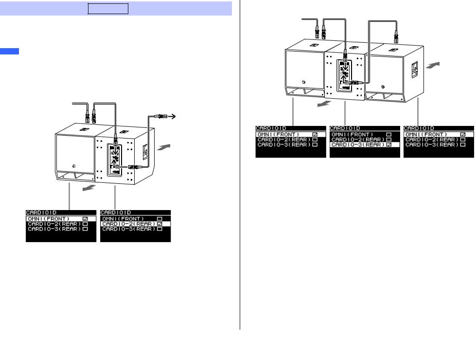
Screen when three subwoofers are placed side by side
CARDIOID Screen Subwoofer
From the mixer
Sets the cardioid mode.
Change settings based on the number of speakers in use and their orientation. Set this to
OMNI (FRONT) when not using the cardioid mode.
NOTE |
Stage |
|
For more information about setting up cardioid mode, see the Owner’s Manual. |
||
|
Screen when two subwoofers are placed side by side |
||
From the mixer |
To the full-range |
|
speakers |
||
|
||
|
Audience |
|
|
Stage |
|
Audience
17
Loading...