


SERVICE MANUAL
EF3000iSE
7WL-28197-E0
310140

FOREWORD
This manual was written by the Yamaha Motor Company primarily for use by Yamaha dealers and their qualified mechanics. It is not possible to put an entire mechanic’s education into one manual, so it is assumed that persons using this book to perform maintenance and repairs on Yamaha generators have a basic understanding of the mechanical precepts and procedures inherent to generator repair technology. Without such knowledge, attempted repairs or service to this model may render it unfit for use and/or unsafe.
Yamaha Motor Company Ltd. is continually striving to further improve all models manufactured by Yamaha. Modifications and significant changes in specifications or procedures will be forwarded to all Authorized Yamaha dealers and will, where applicable, appear in future editions of this manual.
NOTE:
This Service Manual contains information regarding periodic maintenance to the emission control system. Please read this material carefully.
EF3000iSE
SERVICE MANUAL ©2002 by Yamaha Motor Co., Ltd.
1st Edition, October 2002
All rights reserved. Any reprinting or unauthorized use without the written permission of Yamaha Motor Co., Ltd. is expressly prohibited.
Printed in Japan
HOW TO USE THIS MANUAL
PARTICULARLY IMPORTANT INFORMATION
This material is distinguished by the following notation.
The Safety Alert Symbol means ATTENTION! BECOME ALERT! YOUR SAFETY IS INVOLVED!
 WARNING
Failure to follow WARNING instructions could result in severe injury or death to the machine operator, a bystander, or a person inspecting or repairing the machine.


 CAUTION:


A CAUTION indicates special precautions that must be taken to avoid damage to the machine.
NOTE:
A NOTE provides key information to make procedures easier or clearer.
MANUAL FORMAT
The procedures in this manual are organized in a sequential, step-by-step format. The information has been compiled to provide the mechanic with an easy to read, handy reference that contains comprehensive explanations of all disassembly, repair, assembly, and inspection operations.
In this revised format, the condition of a faulty component will precede an arrow symbol and the course of action required will follow the symbol, e.g.,
•Bearings
Pitting/damage → Replace.
EXPLODED DIAGRAM
Each chapter provides exploded diagrams before each disassembly section for ease in identifying the correct disassembly and assembly procedures.
1 |
|
2 |
|
|
GEN |
|
INSP |
|
|
INFO |
|
ADJ |
|
|
3 |
|
4 |
|
|
ENG |
|
ELEC – |
+ |
|
5 |
|
|
|
|
SPEC |
|
|
|
|
6 |
|
7 |
|
|
8 |
|
9 |
|
|
|
|
|
T |
|
|
|
|
. |
|
|
|
|
R |
|
|
|
|
. |
|
0 |
|
A |
|
|
B |
|
|
|
|
C |
D |
E |
|
|
E |
|
G |
M |
|
F |
G |
H |
|
|
B |
|
LS |
M |
|
I |
J |
K |
|
|
LT |
|
4 |
New |
|
|
|
|
|
|
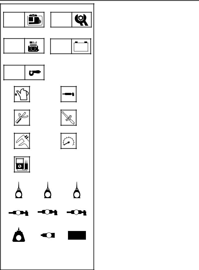
ILLUSTRATED SYMBOLS (Refer to the illustration)
Illustrated symbols 1 through 5 are designed as thumb tabs to indicate the chapter’s number and content.
1 General information
2 Periodic inspections and adjustments
3Engine
4Electrical
5Specifications
Illustrated symbols 6 through B are used to identify the specific tools and test equipment.
6 Filling fluid
7Lubricant
8Special tool
9Tightening
0 Wear limit, clearance A Engine speed
B Ω, V, A
Illustrated symbols C through K in the exploded diagram indicate the grades of lubricant and the locations of the lubrication points.
C Apply engine oil D Apply gear oil
E Apply molybdenum disulfide oil F Apply wheel bearing grease
GApply lightweight lithium-soap base grease
HApply molybdenum disulfide grease
IApply a locking agent (LOCTITE®)
JApply Yamaha bond
KUse a new one
INDEX
GENERAL
INFORMATION
PERIODIC INSPECTIONS AND ADJUSTMENTS
ENGINE
ELECTRICAL
SPECIFICATIONS

CHAPTER 1.
GENERAL INFORMATION
MACHINE IDENTIFICATION .................... |
1-1 |
SERIAL NUMBER ............................... |
1-1 |
STARTING SERIAL NUMBER ............ |
1-1 |
IMPORTANT INFORMATION .................. |
1-2 |
PREPARATION FOR REMOVAL |
|
AND DISASSEMBLY |
|
CAUTION ON SERVICE ..................... |
1-2 |
NOTES ON SERVICE ......................... |
1-2 |
ALL REPLACEMENT PARTS ............. |
1-3 |
GASKETS, OIL SEALS, |
|
AND O-RINGS ..................................... |
1-3 |
BEARINGS AND OIL SEALS .............. |
1-3 |
SPECIAL TOOLS AND TESTERS ........... |
1-4 |
CHAPTER 2.
PERIODIC INSPECTIONS
AND ADJUSTMENTS
INTRODUCTION ....................................... |
2-1 |
MAINTENANCE INTERVALS CHART |
|
(For Canada) ............................................ |
2-1 |
PERIODIC MAINTENANCE/ |
|
LUBRICATION INTERVALS .................... |
2-1 |
COVERS, PANELS, AND CAPS .............. |
2-2 |
ENGINE .................................................... |
2-3 |
ENGINE OIL LEAKAGE CHECKING .. 2-3 |
|
OIL LEVEL CHECKING ....................... |
2-3 |
OIL REPLACEMENT ........................... |
2-4 |
FUEL LEAKAGE .................................. |
2-5 |
FUEL TANK FILTER ........................... |
2-6 |
FUEL PIPE STRAINER ....................... |
2-7 |
AIR FILTER ELEMENT ....................... |
2-8 |
MUFFLER ............................................ |
2-9 |
VALVE CLEARANCE |
|
ADJUSTMENT .................................. |
2-10 |
AIR GAP BETWEEN TCI UNIT |
|
AND FLYWHEEL MAGNETO ........... |
2-13 |
COMPRESSION PRESSURE ........... |
2-14 |
ENGINE SPEED (NO LOAD) ............ |
2-16 |
ECONOMY ENGINE SPEED ............ |
2-16 |
CHOKE CABLE ................................. |
2-17 |
BREATHER HOSE ............................ |
2-17 |
ELECTRICAL ......................................... |
2-18 |
SPARK PLUG ................................... |
2-18 |
MAIN SWITCH .................................. |
2-19 |
ECONOMY SWITCH ........................ |
2-20 |
PILOT LIGHT .................................... |
2-20 |
OVERLOAD WARNING LIGHT ........ |
2-20 |
DC CIRCUIT BREAKER ................... |
2-21 |
DC CIRCUIT BREAKER |
|
(120 V-60 Hz) .................................... |
2-21 |
RECEPTACLE .................................. |
2-22 |
AC SWITCH (NFB) |
|
(120 V-60 Hz/23.5 A) ........................ |
2-22 |
AC SWITCH (NFB) |
|
(120 V-60 Hz/15 A) ........................... |
2-23 |
FUSES .............................................. |
2-23 |
BATTERY .......................................... |
2-25 |
BATTERY TERMINAL ...................... |
2-25 |
BATTERY ELECTROLYTE ............... |
2-26 |
BATTERY CHARGING ..................... |
2-29 |
CHAPTER 3.
ENGINE
PANELS AND COVERS .......................... |
3-1 |
CONTROL PANEL ................................... |
3-3 |
FUEL TANK AND CONTROL BOX ......... |
3-5 |
AIR FILTER ASSEMBLY |
|
AND CONTROL UNIT .............................. |
3-7 |
120 V-60 Hz, 220 V-50 Hz .................. |
3-7 |
AIR FILTER ASSEMBLY, CONTROL UNIT |
|
AND NOISE FILTER ................................ |
3-8 |
230 V-50 Hz ........................................ |
3-8 |
RECOIL STARTER |
|
AND FLYWHEEL MAGNETO .................. |
3-9 |
RECOIL STARTER REMOVAL ........ |
3-12 |
FLYWHEEL MAGNETO |
|
REMOVAL ......................................... |
3-12 |
FLYWHEEL MAGNETO |
|
INSTALLATION ................................. |
3-13 |
RECOIL STARTER |
|
DISASSEMBLY ................................. |
3-14 |
RECOIL STARTER INSPECTION .... |
3-14 |
RECOIL STARTER ASSEMBLY ....... |
3-15 |
ENGINE ASSEMBLY ............................. |
3-17 |
CHASSIS AND CASTERS ..................... |
3-18 |
MUFFLER .............................................. |
3-19 |
MUFFLER INSTALLATION ............... |
3-20 |

GENERATOR ......................................... |
3-21 |
GENERATOR ASSEMBLY |
|
REMOVAL ......................................... |
3-22 |
GENERATOR ASSEMBLY |
|
INSTALLATION ................................. |
3-23 |
CYLINDER HEAD COVER |
|
AND CYLINDER HEAD .......................... |
3-25 |
CYLINDER HEAD REMOVAL ........... |
3-26 |
PUSH ROD INSPECTION ................. |
3-26 |
CYLINDER HEAD INSPECTION ...... |
3-26 |
CYLINDER HEAD ASSEMBLY ......... |
3-27 |
BREATHER HOSE ............................ |
3-27 |
VALVE .................................................... |
3-28 |
VALVE AND VALVE SPRING |
|
REMOVAL ......................................... |
3-29 |
VALVE AND VALVE SPRING |
|
INSPECTION ..................................... |
3-29 |
LOCKER ARM INSPECTION ............ |
3-30 |
VALVE SEAT INSPECTION .............. |
3-31 |
VALVE LAPPING .............................. |
3-32 |
VALVE AND VALVE SPRING |
|
ASSEMBLY ....................................... |
3-33 |
CRANKCASE COVER |
|
AND CAMSHAFT ................................... |
3-34 |
CRANKCASE COVER REMOVAL .... |
3-35 |
CAMSHAFT INSPECTION ................ |
3-35 |
VALVE LIFTER INSPECTION ........... |
3-36 |
CAMSHAFT ASSEMBLY .................. |
3-36 |
CRANKCASE COVER |
|
INSPECTION ..................................... |
3-36 |
CRANKCASE COVER |
|
INSTALLATION ................................. |
3-36 |
PISTON, CONNECTING ROD, |
|
CRANKSHAFT AND CRANKCASE ...... |
3-37 |
CRANKCASE (CYLINDER) |
|
INSPECTION ..................................... |
3-38 |
PISTON AND PISTON PIN |
|
INSPECTION ..................................... |
3-38 |
PISTON RING INSPECTION ............ |
3-40 |
CRANKSHAFT INSPECTION ........... |
3-41 |
CONNECTING ROD OIL |
|
CLEARANCE INSPECTION .............. |
3-42 |
PISTON RING |
|
AND PISTON ASSEMBLY ................ |
3-43 |
CRANKSHAFT ASSEMBLY .............. |
3-44 |
CARBURETOR ...................................... |
3-45 |
FLOAT HEIGHT INSPECTION ......... |
3-49 |
CHOKE CABLE INSTALLATION ...... |
3-50 |
THROTTLE CONTROL MOTOR ...... |
3-50 |
TROUBLESHOOTING ........................... |
3-51 |
THROTTLE CONTROL SYSTEM ..... |
3-56 |
CHAPTER 4.
ELECTRICAL
ELECTRICAL COMPONENTS ................ |
4-1 |
120 V-60 Hz ........................................ |
4-1 |
220 V-50 Hz ........................................ |
4-2 |
230 V-50 Hz ........................................ |
4-3 |
SWITCHES ............................................... |
4-4 |
CHECKING SWITCH CONTINUITY ... |
4-4 |
IGNITION SYSTEM .................................. |
4-5 |
TROUBLESHOOTING CHART ........... |
4-5 |
ELECTRIC STARTING SYSTEM ........... |
4-11 |
TROUBLESHOOTING CHART ......... |
4-11 |
STARTER MOTOR ........................... |
4-14 |
CHARGING SYSTEM ............................ |
4-17 |
TROUBLESHOOTING CHART ......... |
4-17 |
GENERATOR SYSTEM ......................... |
4-20 |
TROUBLESHOOTING CHART ......... |
4-20 |
CHAPTER 5.
SPECIFICATIONS
GENERAL SPECIFICATIONS ................. |
5-1 |
MAINTENANCE SPECIFICATIONS ........ |
5-4 |
ENGINE .............................................. |
5-4 |
GENERATOR AND ELECTRICAL ...... |
5-7 |
LUBRICATION POINTS |
|
AND LUBRICANT TYPES ....................... |
5-8 |
TIGHTENING TORQUE ........................... |
5-9 |
GENERAL TORQUE |
|
SPECIFICATIONS ................................. |
5-11 |
DEFINITION OF UNITS ......................... |
5-11 |
WIRE ROUTING DIAGRAM ................... |
5-12 |
|
|
GEN |
|
MACHINE IDENTIFICATION INFO |
|
|
|
GENERAL INFORMATION |
|
|
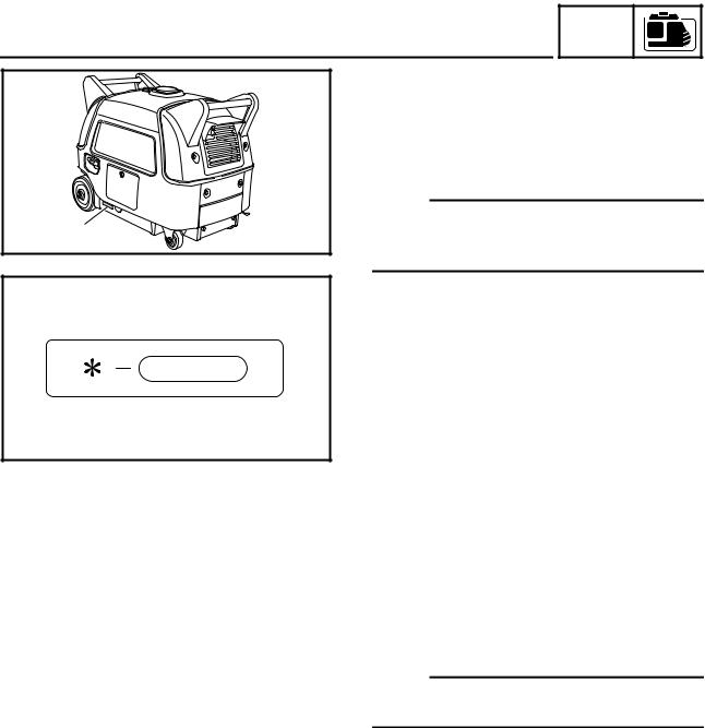
MACHINE IDENTIFICATION |
|
|
SERIAL NUMBER |
|
|
The serial number is printed on a label 1 |
|
|
which is affixed to the generator as shown. |
|
|
NOTE: |
1 |
|
The first three characters of this number are |
|
for model identification, the remaining digits |
|
|
SWL1010T |
|
|
are the unit production number. |
|
|
|
|
SWL1020J
STARTING SERIAL NUMBER
Model |
Code |
Starting serial |
|
number |
|||
|
|
||
|
|
|
|
120 V-60 Hz |
7WL2 |
7WL-220101~ |
|
|
|
|
|
220 V-50 Hz |
7WL3 |
7WL-330101~ |
|
|
|
|
|
230 V-50 Hz |
7WL3 |
7WL-300101~ |
|
|
|
|
|
230 V-50 Hz |
7WL3 |
7WL-350101~ |
|
|
|
|
NOTE:
Designs and specifications are subject to change without notice.
1-1
GEN
IMPORTANT INFORMATION INFO
IMPORTANT INFORMATION
PREPARATION FOR REMOVAL AND DISASSEMBLY
CAUTION ON SERVICE
1.Fire prevention
When servicing the engine, always keep the engine and yourself
SVU1030
away from fire.
NOTES ON SERVICE
1.Correct tools
Be sure to use the correct special tool for the job to guard against damage.
SVU1040
2.Oil, grease and seals
Be sure to use genuine Yamaha oils, grease and sealers, or the
equivalents.
SVU1050
3.Expendable parts
Always replace the gaskets, O-rings, cotter pins and circlips with new parts when servicing engine.
SVU1060
SVU1070
SVU1080
SVU1090
4.Tightening torque
Be sure to follow torque specifications. When tightening bolts, nuts or screws, start with the largest-diameter fastener and work from an inner position to an outer position in a crisscross pattern.
5.Notes on disassembly and assembly
a.Parts should be cleaned in solvent and blown dry with compressed air after disassembly.
b.Contact surfaces of moving parts should be oiled when reassembled.
c.Make sure that the parts move smoothly after each section of the machine is assembled.
SVU1100
1-2

|
|
|
|
|
|
|
|
|
|
IMPORTANT INFORMATION |
|
GEN |
|
|
|
|
|
|
INFO |
|
|
||
|
|
|
|
|
|
|
|
|
|
ALL REPLACEMENT PARTS |
|||||
|
|
We recommend the use of genuine Yamaha parts for all replace- |
|||||
|
|
ments. Use oil and/or grease, recommended by Yamaha, for |
|||||
|
|
assembly and adjustment. |
|||||
|
|
GASKETS, OIL SEALS, AND O-RINGS |
|||||
|
|
1. All gaskets, seals, and O-rings should be replaced when an |
|||||
|
|
engine is overhauled. All gaskets surfaces, oil seal lips, and O- |
|||||
|
|
rings must be cleaned. |
|||||
|
|
2. Properly oil all mating parts and bearings during reassembly. |
|||||
|
|
Apply grease to the oil seal lips. |
|||||
|
|
BEARINGS AND OIL SEALS |
|||||
|
|
||||||
|
|
Install the bearing(s) 1 and oil seal(s) 2 with their manufacture’s |
|||||
|
|
marks or numbers facing outward. (In other words, the stamped let- |
|||||
|
|
ters must be on the side exposed to view.) When installing oil |
|||||
|
|
seal(s), apply a light coating of light-weight lithium base grease to |
|||||
SVU1110 |
|
the seal lip(s). Oil the bearings liberally when installing. |
|||||
|
|
||||||
|
|
||||||
|
|
CAUTION: |
|
||||
|
|
||||||
|
|
Do not use compressed air to spin the bearings dry. This |
|||||
|
|
causes damage to the bearing surfaces. |
|||||
SVU1120 |
|
|
|
|
|
|
|
|
|
|
|
|
|
|
|
|
|
|
|
|
|
|
|
1-3
GEN
SPECIAL TOOLS AND TESTERS INFO
SPECIAL TOOLS AND TESTERS
The proper special tools are necessary for complete and accurate tune-up and assembly. Using the correct special tool will help prevent damage caused by the use of improper tools or improvised techniques. The shape and part number used for the special tool differ by country, so two types are provided. Refer to the list provided to avoid errors when placing an order.
NOTE:
•For USA and Canada, use part number starting with “YM-”, “YU-” or “YS-”.
•For others, use part number starting with “90890-”.
1.Piston ring compressor
P/N. YU-33294, 90890-05158
This tool is used to compress the piston rings when installing the piston.
SVU1130
2.Valve spring compressor P/N. YM-01253, 90890-01253
This tool is used to remove the valve springs.
SVU1140
3.Thickness gauge
P/N. YU-26900-9, 90890-03079
This gauge is used to adjust valve clearance, piston clearance and piston ring end gap.
SVU1150
4.Cylinder gauge Commercially available
This instrument is used for checking cylinder bore size and condition.
SVU1160
1-4
|
|
|
|
|
|
|
|
|
SPECIAL TOOLS AND TESTERS |
|
GEN |
|
|
|
|
|
INFO |
|
|
|
|
|
|
|
|
|
|
|
|
5. Inductive self-powered tachometer |
||||
1 |
|
|||||
|
1 P/N. YU-8036-B |
|||||
|
|
|||||
|
|
Engine tachometer |
||||
|
|
2 P/N. 90890-03113 |
||||
|
|
3 P/N. 90793-80009 |
||||
|
SWL1010 |
4 P/N. 90793-80032 |
||||
|
|
|||||
|
|
|||||
|
This instrument is used for reading engine r/min. |
|
2 |
||
|
SWL1020
3
SWL1040
4
SWL1050
6.Compression gauge 1
P/N. YU-33223, 90890-03081 Adapter 2
P/N. YU-33223-3, 90890-04082
This gauge is used for checking engine compression.
SVU1180
7.Dial gauge
P/N. YU-03097, 90890-03097
This instrument is used for checking crankshaft side clearance.
SVU1190
8.Piston pin puller
P/N. YU-01304, 90890-01304
This tool is used to remove the piston pin.
SVU1200
9.Sheave holder
P/N. YS-01880-A, 90890-01701
This tool is necessary for holding the flywheel or rotor.
SVU1205
1-5

|
|
|
|
|
|
|
|
|
SPECIAL TOOLS AND TESTERS |
|
GEN |
|
|
|
|
|
INFO |
|
|
|
|
|
|
|
|
|
|
|
|
10.Rotor assembly holder |
||||
|
|
|||||
|
|
Commercially available |
||||
|
|
This tool is necessary for holding the rotor. |
||||
|
SWL1030 |
|
||||
|
|
11.Rotor puller |
||||
|
|
|||||
1 |
|
|||||
|
|
1 P/N. YU-33270-B |
||||
|
|
2 P/N. 90890-01362 |
||||
|
|
This tool is necessary for removing the flywheel. |
||||
|
SVU1210 |
|
||||
|
|
|
|
|
|
|
2
SVU1220
SVU1230
1
SVU1240
2
SVU1250
12.Pocket tester
P/N. YU-03112-C, 90890-03112
This instrument is necessary for checking the electrical system.
13.Dynamic spark tester 1 P/N. YM-34487
Ignition checker 2 P/N. 90890-06754
This instrument is necessary for checking the ignition system components.
14.MF Battery charging Commercially available
This instrument is necessary for charging the electrical system.
SWL1060
1-6

INTRODUCTION/MAINTENANCE INTERVALS CHART (For Canada)/
PERIODIC MAINTENANCE/LUBRICATION INTERVALS
INSP ADJ
PERIODIC INSPECTIONS AND ADJUSTMENTS
INTRODUCTION
This chapter includes all information necessary to perform recommended inspections and adjustments. These preventive maintenance procedures, if followed, will ensure more reliable machine operation and a longer service life. The need for costly overhaul work will be greatly reduced. This information applies to machines already in service as well as new machines that are being prepared for sale. All service technicians should be familiar with this entire chapter.
MAINTENANCE INTERVALS CHART (For Canada)
Proper periodic maintenance is important. Especially important are the maintenance services related to emissions control. These controls not only function to ensure cleaner air but are also vital to proper engine operation and maximum performance. In the following maintenance tables, the services related to emissions control are indicated as “*” in the chart.
PERIODIC MAINTENANCE/LUBRICATION INTERVALS
|
È |
|
É |
Ê |
Ë |
Ì |
Í |
Î |
|
|
|
|
Pre-Opera- |
Initial |
Every |
Every |
Every |
|
Item |
|
Remarks |
tion check |
1 month |
3 months |
6 months |
12 months |
|
|
|
|
(daily) |
or 20 Hr |
or 50 Hr |
or 100 Hr |
or 300 Hr |
|
|
|
|
|
|
|
|
|
Ï *Spark Plug |
Check condition. Adjust gap and clean. |
|
|
● |
|
|
||
Replace if necessary. |
|
|
|
|
||||
|
|
|
|
|
|
|
||
|
|
|
|
|
|
|
||
Ð *Valve Clearance |
Check and adjust when engine is cold. |
|
|
|
|
● |
||
|
|
|
|
|
|
|
|
|
Ñ |
*Crankcase breather |
Check breather hose for cracks or damage. |
|
|
|
|
● |
|
|
system |
Replace if necessary. |
|
|
|
|
|
|
Ò *Idle speed |
Check and adjust engine idle speed. |
|
|
|
|
● |
||
|
|
|
|
|
|
|
|
|
|
|
Ô |
Check for leakage. |
● |
|
|
|
|
Ó *Exhaust System |
|
Retighten or replace gasket if necessary. |
|
|
|
|
|
|
Õ |
Check muffler screen and spark arrester. |
|
|
|
|
● |
||
|
|
|
|
|
|
|||
|
|
|
Clean/replace if necessary. |
|
|
|
|
|
Ö Engine Oil |
× Check oil level. |
● |
|
|
|
|
||
|
|
|
|
|
|
|
||
Ø Replace. |
|
● |
|
● |
|
|||
|
|
|
|
|
||||
|
|
|
|
|
|
|
|
|
Ù *Air Filter |
Clean. |
|
|
● |
|
|
||
Replace if necessary. |
|
|
|
|
||||
|
|
|
|
|
|
|
||
|
|
|
|
|
|
|
|
|
Ú Fuel Filter |
Clean fuel tank filter. |
|
|
|
● |
|
||
Replace if necessary. |
|
|
|
|
||||
|
|
|
|
|
|
|
||
|
|
|
|
|
|
|
|
|
Û Fuel Line |
Check fuel hose for crack or damage. Replace |
● |
|
|
|
|
||
if necessary. |
|
|
|
|
||||
|
|
|
|
|
|
|
||
|
|
|
|
|
|
|
||
Ü *Choke knob |
Check choke operation. |
● |
|
|
|
|
||
|
|
|
|
|
|
|
||
Ý Cooling System |
Check for fan damage. |
|
|
|
|
● |
||
|
|
|
|
|
|
|
|
|
Þ Starting System |
ß Check recoil starter operation. |
● |
|
|
|
|
||
|
|
|
|
|
|
|
||
À Check electric starter operation. |
● |
|
|
|
|
|||
|
|
|
|
|
|
|||
|
|
|
|
|
|
|
||
Á *Decarbonization |
More frequently if necessary. |
|
|
|
|
● |
||
|
|
|
|
|
|
|
||
+ Generation |
Check the pilot light comes on. |
● |
|
|
|
|
||
|
|
|
|
|
|
|
|
|
, Fittings/Fasteners |
Check all fittings and fasteners. |
|
|
|
● |
|
||
Correct if necessary. |
|
|
|
|
||||
|
|
|
|
|
|
|
||
|
|
|
|
|
|
|
|
|
*: Related to emission control system.
2-1

INSP
COVERS, PANELS, AND CAPS ADJ
COVERS, PANELS, AND CAPS
Front right view |
|
|
Rear left view |
1 |
|
|
9 |
|
|
|
8 |
7 |
|
2 |
0 |
|
|
|
|
|
|
|
C |
6 |
3 |
|
B |
5 |
|
|
A |
4 |
|
|
|
|
|
|
SWL2180T |
1 Cover 1 |
7.0 Nm (0.7 m · kg, 5.1 ft · lb) |
2 Panel 1 |
|
7.0 Nm (0.7 m · kg, 5.1 ft · lb) |
|
3 Cover 2 |
|
7.0 Nm (0.7 m · kg, 5.1 ft · lb) |
|
4 Cover 3 |
|
7.0 Nm (0.7 m · kg, 5.1 ft · lb) |
|
5 Cap 1 |
|
6 Cap 2 |
|
7 Panel 2 |
|
8 Cover 4 |
|
7.0 Nm (0.7 m · kg, 5.1 ft · lb) |
|
9 Cover 5 |
|
7.0 Nm (0.7 m · kg, 5.1 ft · lb) |
|
0 Panel 3 |
|
7.0 Nm (0.7 m · kg, 5.1 ft · lb) |
|
A Battery bracket |
|
7.0 Nm (0.7 m · kg, 5.1 ft · lb) |
|
B Panel 4 |
|
C Cover 6 |
|
7.0 Nm (0.7 m · kg, 5.1 ft · lb) |
NOTE:
•The EF3000iSE are equipped with soundproof covers and panels that cover the engine and frame.
•To make periodic maintenance checks easy, remove the applicable cover or panel.
•For cover or panel removal and installation, refer to “PANELS AND COVERS” in CHAPTER 3.
2-2
ENGINE OIL LEAKAGE CHECKING/ |
|
|
|
|
|
INSP |
|
|
|
OIL LEVEL CHECKING |
|
ADJ |
|
|
|
|
|
|
|
|
ENGINE |
||
|
ENGINE OIL LEAKAGE CHECKING |
||
|
1. Remove: |
||
|
|
• |
Panel 2 |
|
|
• |
Panel 4 |
|
|
|
Refer to “COVERS, PANELS, AND |
|
|
|
CAPS”. |
|
2. Check the areas outside of the engine for |
||
SWL2020J |
|
oil leakage. |
|
|
|
|
Oil leakage → Replace the gasket, oil |
|
|
|
|
|
|
|
seal, or O-ring. |
3. |
Install: |
||
|
|
• |
Panel 4 |
|
|
• |
Panel 2 |
|
|
|
Refer to “COVERS, PANELS, AND |
|
|
|
CAPS”. |
|
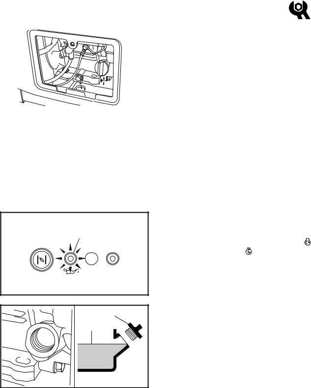
OIL LEVEL CHECKING |
|
|
||
|
1. Check: |
|
|
||
1 |
• Oil level with oil level warning light 1 |
|
|||
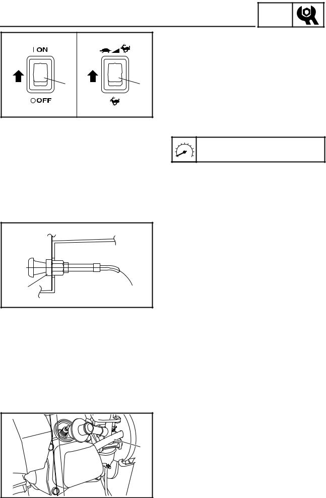
• |
Set the main switch to “START” “ |
” |
|||
|
|||||
|
|
or set it to “ON” “ |
” and pull the recoil |
||
|
|
starter to check that the oil level warn- |
|||
|
|
ing light 1 flashes. |
|
|
|
|
|
Oil level warning light flashes → Add |
|||
|
SWL2010T |
oil. |
|
|
|
|
Oil level warning light does not flash |
→ |
|||
|
|
||||
|
|
OK |
|
|
|
1 |
2. Remove: |
|
|
||
a |
• |
Panel 2 |
|
|
|
|
Refer to “COVERS, PANELS, AND |
||||
|
|
||||
|
|
CAPS”. |
|
|
|
|
• Oil filler cap 1 |
|
|
||
|
3. Check: |
|
|
||
|
• Check that the engine oil is at the spec- |
||||
|
SWL2040J |
ified level a. |
|
|
|
|
|
|
|
||
|
Oil level checking steps: |
|
|||
|
• Place the generator on a level surface. |
|
|||
|
• Warm up the engine for several minutes. |
||||
|
• Stop the engine. |
|
|
||
|
• Check that the engine oil is at the specified |
||||
|
level a. Add oil if necessary. |
|
|||
2-3

OIL LEVEL CHECKING/ OIL REPLACEMENT
INSP ADJ
1

SWL2050J
4.Install:
•Oil filler cap
•Panel 2
Refer to “COVERS, PANELS, AND CAPS”.
NOTE:
Tighten the oil filler cap securely by hand.
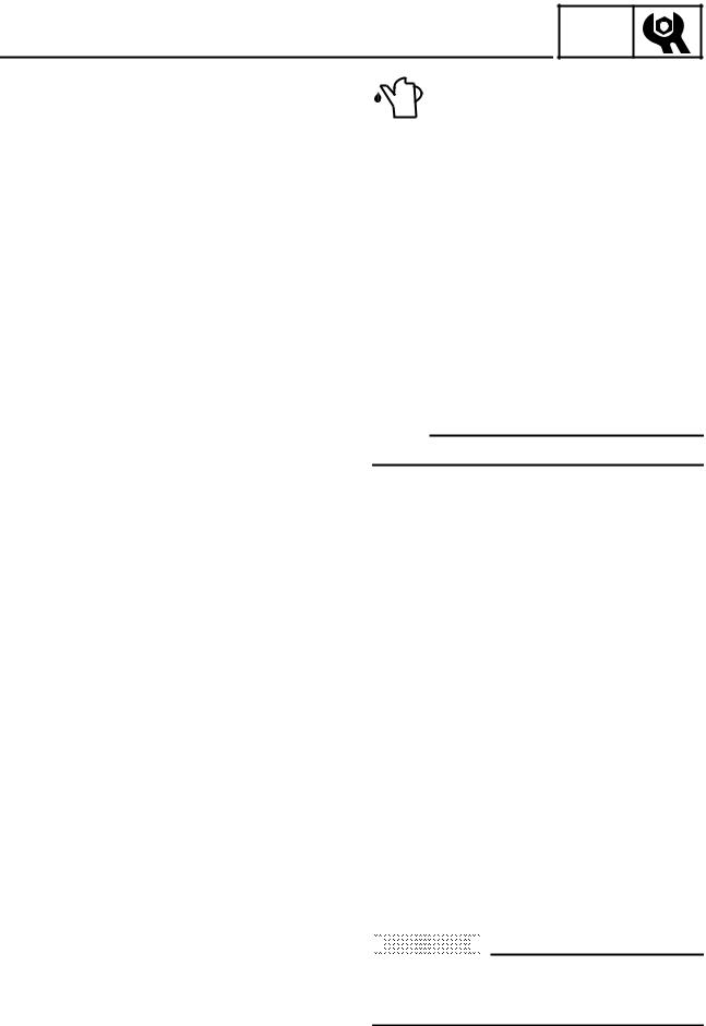
OIL REPLACEMENT
1.Warm up the engine for several minutes.
2.Stop the engine.
3.Remove:
•Panel 2
•Cap 2
•Cap 1
Refer to “COVERS, PANELS, AND CAPS”.
4.Place a receptacle under the engine.
5.Remove:
•Oil drain bolt 1
6.Tilt the engine to drain the oil completely.
7.Tighten:
•Oil drain bolt
|
Oil drain bolt: |
. |
17 Nm (1.7 m · kg, 12 ft · lb) |
T |
|
R |
|
. |
|
|
|
8. Remove: |
|
|
• Oil filler cap 1 |
|
|
9. Fill: |
|
|
Recommended oil: |
|
|
È YAMALUBE 4 (10W-30) or SAE |
|
|
10W-30 type SE |
|
|
É SAE #30 |
|
1 |
Ê SAE #20 |
|
Ë SAE 10W |
|
SWL2060J |
|
|
|
Engine oil quantity: |
|
|
|
|
È |
|
0.6 L (0.53 Imp qt, 0.63 US qt) |
|
|
|
|
|
NOTE: |
|
|
Recommended engine oil classification: |
|
|
API Service “SE” or “SF”, if not available, “SD”. |
SVU2060
2-4
OIL REPLACEMENT/ FUEL LEAKAGE
INSP ADJ
É |
|
|
|
|
Recommended oil: |
|
|
|
|
|
|
||
|
|
|
|
|
È SAE #30 |
or 10W-30 |
|
|
|
|
|
|
or 10W-40 |
|
|
|
|
|
|
|
|
|
|
|
|
É SAE #20 |
or 10W-30 |
|
|
|
|
|
|
or 10W-40 |
|
|
|
|
|
Ê SAE 10W |
or 10W-30 |
|
|
|
|
|
|
or 10W-40 |
|
|
|
|
|
SAE #40: Above 35 °C (95 °F) |
|
|
|
|
|
|
Engine oil quantity: |
|
SVW2070T |
|
|
|
|
0.6 L (0.53 Imp qt, 0.63 US qt) |
|
|
|
|
|
|
||
|
|
|
|
|
|
|
|
|
NOTE: |
|
|
||
|
|
Recommended engine oil classification: |
||||
|
|
API Service “SE” or “SF”, if not available, “SD”. |
||||
|
|
|
|
|
||
|
|
È For Canada |
|
|||
|
|
É Except for Canada |
|
|||
|
|
10.Install: |
|
|||
|
|
• |
Oil filler cap |
|
||
NOTE:
Tighten the oil filler cap securely by hand.
11.Install:
• Cap 1
• Cap 2
• Panel 2
Refer to “COVERS, PANELS, AND CAPS”.
FUEL LEAKAGE
1. Remove:
• Cover 1
• Cover 5
• Cover 4
Refer to “COVERS, PANELS, AND CAPS”.
2. Remove:
• Fuel tank bolts
Refer to “FUEL TANK AND CONTROL BOX” in CHAPTER 3.
3. Slide the fuel tank to check for leakage.

 CAUTION:

When sliding the fuel tank, be sure not to extremely bend, twist, or pull the fuel hoses.
2-5
FUEL LEAKAGE/ FUEL TANK FILTER
INSP ADJ
|
|
4. Check: |
|||
|
|
|
• |
Leakage |
|
|
|
|
|
Check at fuel tank, fuel cock, fuel |
|
|
|
|
|
hoses, and carburetor. |
|
|
|
CAUTION: |
|
||
|
|
Replace the fuel hoses every four years. |
|||
|
|
|
|
||
|
5. |
Install: |
|||
SWL2070J |
|
• |
Fuel tank |
||
|
|
|
|
Refer to “FUEL TANK AND CONTROL |
|
|
|
|
|
||
|
|
|
|
BOX” in CHAPTER 3. |
|
6. |
Install: |
||||
|
|
|
• |
Cover 4 |
|
|
|
|
• |
Cover 5 |
|
|
|
|
• |
Cover 1 |
|
|
|
|
|
Refer to “COVERS, PANELS, AND |
|
|
|
|
|
CAPS”. |
|
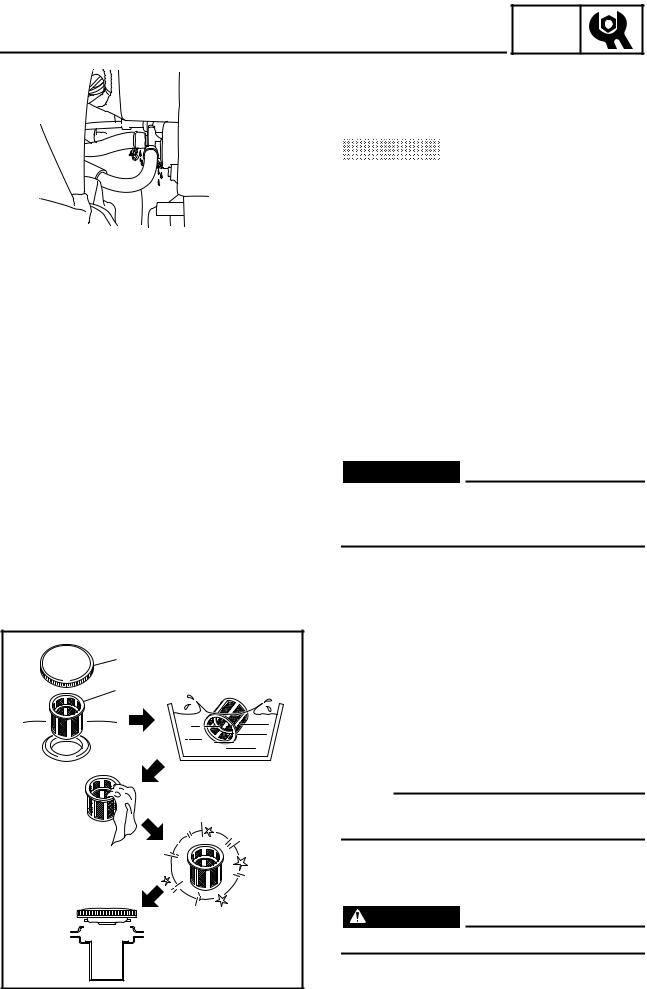
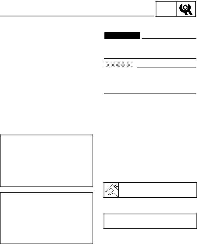
FUEL TANK FILTER
 WARNING
Do not smoke, and keep away from open flames, sparks, or any other source of fire when handling or in the vicinity of fuel.
|
1. |
Remove: |
|
1 |
|
• Fuel tank cap 1 |
|
|
|
• Fuel tank filter 2 |
|
2 |
2. |
Inspect: |
|
|
|
• |
Fuel tank filter |
|
|
|
Damage → Replace. |
|
3. |
Clean: |
|
|
|
• |
Fuel tank filter |
|
NOTE: |
||
|
Clean the fuel tank filter with solvent, and then |
||
|
dry it thoroughly. |
||
|
4. |
Install: |
|
|
|
• |
Fuel tank filter |
|
|
• |
Fuel tank cap |
|
|
WARNING |
|
|
Be sure the tank cap is tightened securely. |
||
|
SVU2080J |
|
|
2-6

FUEL PIPE STRAINER
FUEL PIPE STRAINER
INSP ADJ
|
WARNING |
|
Do not smoke, and keep away from open |
||
flames, sparks, or any other source of fire |
||
when handling or in the vicinity of fuel. |
||
1. |
Drain the fuel. |
|
2. |
Remove: |
|
|
• |
Cover 1 |
|
• |
Cover 5 |
|
• |
Cover 4 |
|
|
Refer to “COVERS, PANELS, AND |
|
|
CAPS”. |
3. |
Remove: |
|
|
• Fuel hose (fuel cock end) |
|
|
• |
Fuel tank |
|
|
Refer to “FUEL TANK AND CONTROL |
|
|
BOX” in CHAPTER 3. |
4. |
Remove: |
|
1 |
• |
Fuel hose (fuel tank end) |
|
• Fuel pipe strainer 1 |
|
5. |
Inspect: |
|
|
• |
Fuel pipe strainer |
|
|
Damage → Replace. |
6. |
Clean: |
|
|
• |
Fuel pipe strainer |
NOTE: |
||
Clean the fuel pipe strainer with solvent, and |
||
then dry it thoroughly. |
||
7. |
Install: |
|
|
• |
Fuel pipe strainer |
|
• Fuel hose (fuel tank end) |
|
8. |
Install: |
|
|
• |
Fuel tank |
|
• Fuel hose (fuel cock end) |
|
|
|
Refer to “FUEL TANK AND CONTROL |
SWL2080J |
|
BOX” in CHAPTER 3. |
|
|
|
9. |
Install: |
|
|
• |
Cover 4 |
|
• |
Cover 5 |
|
• |
Cover 1 |
|
|
Refer to “COVERS, PANELS, AND |
|
|
CAPS”. |
2-7

INSP
AIR FILTER ELEMENT ADJ
1 |
2 |
1 |
SWL2090J |
2 |
1 |
SVU2100J |
SWL2110 |
AIR FILTER ELEMENT
1.Remove:
•Panel 4
•Cover 5
Refer to “COVERS, PANELS, AND CAPS”.
2.Remove:
•Hooks 1
•Air filter element case 2
3.Remove:
•Air filter element 1 1
•Air filter element 2 2
NOTE:
Remove air filter element 1 and air filter element 2 as a set.
4.Inspect:
•Air filter elements Damage → Replace.
5.Clean:
•Air filter element 1
Wash the air filter elements in kerosene.
NOTE:
Be sure to squeeze the excess kerosene out of the air filter element 1.
6.Lubricate:
•Air filter element 1
Soak the air filter element 1 in a 2–4:1 mixture of kerosene and engine oil.
NOTE:
Be sure to squeeze the excess kerosene and engine oil out of the air filter element 1.


 CAUTION:


•Do not twist the air filter elements, otherwise they can tear.
•Do not wash the air filter elements in gasoline or in acid, alkaline, or organic solvents.
7.Install:
•Air filter element 1
•Air filter element 2
NOTE:
Insert air filter element 1 into air filter element 2, and then install them into the air filter case.
2-8
AIR FILTER ELEMENT/ MUFFLER
INSP ADJ
SWL2120J |
|
|
2 |
|
2 |
1 |
4 |
|
a |
|
|
|
|
|
b |
6 |
3 |
|
|
|
|
|
5 |
8.Install:
•Air filter element case 1
•Hooks 2
NOTE:
•Align the projection a of the air filter case 1 with the slot b in the air filter element bracket, and then install the air filter case.
•Make sure that the air intake duct 3 is securely installed onto the frame 4.
•Make sure that the air vent hose 5 and drain hose 6 are securely installed onto the frame 4.
9.Install:
•Cover 5
•Panel 4
Refer to “COVERS, PANELS, AND CAPS”.


 CAUTION:


The engine should never run without the air filter element installed, otherwise excessive piston and/or cylinder wear may result.
MUFFLER
1.Remove:
•Engine assembly
Refer to “ENGINE ASSEMBLY” in CHAPTER 3.
2.Remove:
•Muffler
Refer to “MUFFLER” in CHAPTER 3.
3.Remove:
•Muffler band 1
•Muffler cap 2
•Muffler screen 3
•Spark arrester 4
SWL2400J
2-9
MUFFLER/ VALVE CLEARANCE ADJUSTMENT
INSP ADJ
SWL2410J
4 |
2 |
|
|
|
1 |
3 |
SWL2130J |
4.Decarbonize:
•Exhaust pipe 1
•Muffler 2
•Muffler screen 3
•Spark arrester 4
Tap on the muffler in the area shown in the illustration to loosen carbon buildup, and then shake it out of the end of the muffler.


 CAUTION:


Do not use a wire to clean the muffler, otherwise the noise damping material may come out, and the damping effect may be reduced.
5.Install:
•Spark arrester
•Muffler screen
•Muffler cap
•Muffler band
•Muffler
Refer to “MUFFLER” in CHAPTER 3.
6.Install:
•Engine assembly
Refer to “ENGINE ASSEMBLY” in CHAPTER 3.
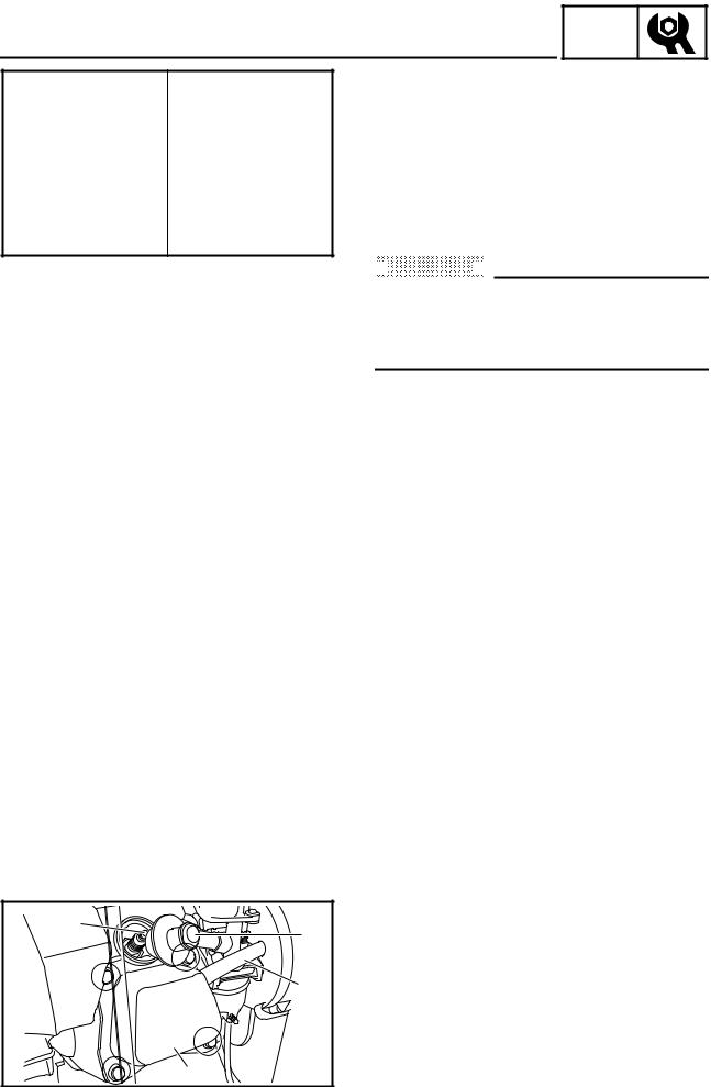
VALVE CLEARANCE ADJUSTMENT
1.Remove:
•Panel 4
Refer to “COVERS, PANELS, AND CAPS”.
2.Remove:
•Breather hose 1
•Spark plug cap 2
•Cylinder head cover 3
•Spark plug 4
2-10
INSP
VALVE CLEARANCE ADJUSTMENT ADJ
SWL2140J |
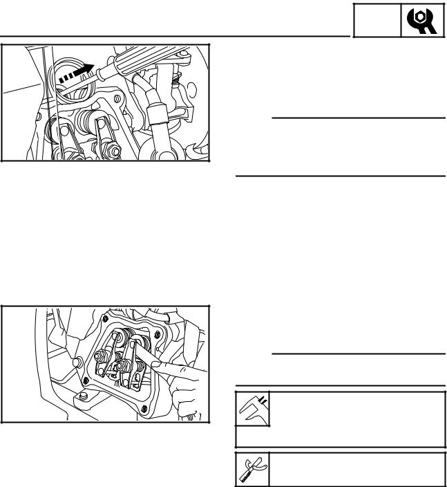
3.Gently pull the recoil starter to bring the piston to top dead center of its compression stroke (when the screwdriver inserted into the spark plug hole reaches the highest position).
NOTE:
If the piston is at top dead center of the exhaust stroke, turn the crankshaft one full turn (360°) to set the piston at top dead center of the compression stroke.
4. Measure:
• Valve clearance
Out of specification → Adjust.
NOTE:
Valve clearance must be measured when the engine is cool to the touch.
Intake valve (cold):
SWL2150J  0.18 ~ 0.22 mm (0.007 ~ 0.009 in)
Exhaust valve (cold):
0.18 ~ 0.22 mm (0.007 ~ 0.009 in)
Thickness gauge:
YU-26900-9, 90890-03079
2-11
INSP
VALVE CLEARANCE ADJUSTMENT ADJ
2 |
1 |
SWL2160J |
1
2 |
|
SWL2170J |
|
1 |
3 |
|
|
|
4 |
2 |
SWL2180J |
|
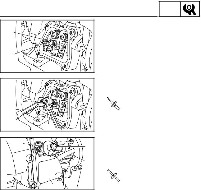
5.Adjust:
• Valve clearance
Adjustment steps:
•Loosen the locknut 1.
•Turn the adjuster 2 in or out to obtain the proper clearance.
Adjuster |
|
Valve clearance |
|
|
|
|
|
Turn in |
|
Decrease |
|
|
|
|
|
Turn out |
|
Increase |
|
|
|
||
• Tighten the locknut 1. |
|||
|
|
|
|
|
Locknut: |
|
|
. |
10 Nm (1.0 m · kg, 7.2 ft · lb) |
||
T |
|
|
|
R |
|
|
|
. |
|
|
|
|
|
|
|
6.Install:
•Spark plug 1
•Cylinder head cover 2
•Spark plug cap 3
•Breather hose 4
|
Cylinder head cover bolt: |
. |
10 Nm (1.0 m · kg, 7.2 ft · lb) |
T |
Spark plug: |
R |
|
. |
|
|
|
|
|
|
18 Nm (1.8 m · kg, 13 ft · lb) |
|
|
7.Install:
•Panel 4
Refer to “COVERS, PANELS, AND CAPS”.
2-12
AIR GAP BETWEEN TCI UNIT AND FLYWHEEL MAGNETO
INSP ADJ
AIR GAP BETWEEN TCI UNIT AND FLYWHEEL MAGNETO
1.Remove:
•Fuel tank
Refer to “FUEL TANK AND CONTROL BOX” in CHAPTER 3.
•Air filter element assembly
Refer to “AIR FILTER ASSEMBLY AND CONTROL UNIT” and “AIR FILTER ASSEMBLY, CONTROL UNIT AND NOISE FILTER” in CHAPTER 3.
•Carburetor
Refer to “CARBURETOR” in CHAPTER 3.
•Recoil starter
•Flywheel magneto cover
Refer to “RECOIL STARTER AND FLYWHEEL MAGNETO” in CHAPTER 3.
2.Measure:
•Air gap between TCI unit and flywheel magneto
Use a thickness gauge 1. Out of specification → Adjust.
|
Thickness gauge: |
|
YU-26900-9, 90890-03079 |
SWL2420J |
3. Adjust: |
• Air gap between TCI unit and flywheel magneto
Adjustment steps:
•Loosen the bolts 2.
•Adjust the air gap between the TCI unit and flywheel magneto by moving the TCI unit up or down.
•Tighten the bolts 2.
T .
R .
Air gap between TCI unit and flywheel magneto:
0.5 ± 0.1 mm (0.020 ± 0.004 in)
TCI unit bolt:
10 Nm (1.0 m · kg, 7.2 ft · lb)
2-13

AIR GAP BETWEEN TCI UNIT AND FLYWHEEL MAGNETO/COMPRESSION PRESSURE
INSP ADJ
4. Install:
• Flywheel magneto cover
• Recoil starter
Refer to “RECOIL STARTER AND FLYWHEEL MAGNETO” in CHAPTER 3.
• Carburetor
Refer to “CARBURETOR” in CHAPTER 3.
• Air filter element assembly
Refer to “AIR FILTER ASSEMBLY AND CONTROL UNIT” and “AIR FILTER ASSEMBLY, CONTROL UNIT AND NOISE FILTER” in CHAPTER 3.
• Fuel tank
Refer to “FUEL TANK AND CONTROL BOX” in CHAPTER 3.
COMPRESSION PRESSURE
NOTE:
Measure the compression after checking and adjusting the valve clearance.
1. Warm up the engine for several minutes.
2. Remove:
• Panel 4
Refer to “COVERS, PANELS, AND CAPS”.
3. Remove:
• Spark plug cap
• Spark plug
|
|
4. Connect: |
|
2 |
1 |
• |
Compression gauge 1 |
|
|
• |
Adapter 2 |
|
|
|
Compression gauge: |
|
|
|
YU-33223, 90890-03081 |
|
|
|
Adapter: |
|
|
|
YU-33223-3, 90890-04082 |
|
SWL2190J |
|
|
|
|
2-14 |
|
INSP
COMPRESSION PRESSURE ADJ
5.Measure:
•Compression
To measure the compression, set the
main switch to “START” “  ” or set it to “ON” “
  ” and pull the recoil starter until the needle stops rising on the com-
pression gauge.
Standard compression pressure: 400 ~ 600 kPa
(4 ~ 6 kg/cm2, 57 ~ 85 psi)
 WARNING
To prevent sparking when cranking the engine, ground the spark plug lead.
Testing steps (below minimum level):
•Squirt a few drops of oil into the cylinder.
•Measure the compression pressure again.
Reading |
|
Diagnosis |
|
|
|
|
|
If higher than |
• |
Worn cylinder, piston, and |
|
without oil |
|
piston ring |
|
|
|
|
|
|
• |
Defective piston, ring(s), |
|
If the same as |
|
valve(s), and cylinder |
|
|
head gasket |
||
without oil |
|
||
• Improper valve timing and |
|||
|
|||
|
|
valve clearance |
|
|
|
|
|
Testing steps (above maximum level):
• Check the cylinder head, valve surfaces, and piston crown for carbon deposits.
6.Install:
•Spark plug
•Spark plug cap
T .
R .
Spark plug:
18 Nm (1.8 m · kg, 13 ft · lb)
7.Install:
•Panel 4
Refer to “COVERS, PANELS, AND CAPS”.
2-15

ENGINE SPEED (NO LOAD)/ ECONOMY ENGINE SPEED
INSP ADJ
|
ENGINE SPEED (NO LOAD) |
|
|
|
|
1. Remove: |
|
|
|
|
• |
Panel 4 |
|
|
|
|
Refer to “COVERS, PANELS, AND |
||
|
|
CAPS”. |
|
|
1 |
2. Connect: |
|
|
|
|
• Inductive self-powered |
tachometer |
or |
|
|
|
engine tachometer 1 |
|
|
|
SWL2200J |
Inductive self-powered tachome- |
||
|
|
|||
|
|
ter: |
|
|
|
|
YU-8036-B |
|
|
|
|
Engine tachometer: |
|
|
|
|
90890-03113 |
|
|
|
|
(90793-80009, 90793-80032) |
|
|
ÈÉ
a |
1 a |
1 |
SWL2020T
1 |
SWL2200J |
3.Inspect:
•Engine speed (no load) Specified engine speed → OK
Out of specification → Refer to “TROUBLESHOOTING” in CHAPTER 3.
Inspection steps:
• Operate the engine (no load).
• Turn the economy switch 1 to “OFF”
“  ” a.
” a.
•Measure the engine speed (no load).
Engine speed (no load): 3,550 r/min
È 120 V-60 Hz, 220 V-50 Hz
É230 V-50 Hz
4.Install:
•Panel 4
Refer to “COVERS, PANELS, AND
CAPS”.
ECONOMY ENGINE SPEED
1.Remove:
•Panel 4
Refer to “COVERS, PANELS, AND CAPS”.
2.Connect:
•Inductive self-powered tachometer or engine tachometer 1
Inductive self-powered tachometer:
YU-8036-B Engine tachometer:
90890-03113
(90793-80009, 90793-80032)
2-16
ECONOMY ENGINE SPEED/ CHOKE CABLE/BREATHER HOSE
INSP ADJ
ÈÉ
a a
1 1
SWL2050T
1
SWL2430J
3.Inspect:
•Economy engine speed Specified engine speed → OK
Out of specification → Refer to “TROUBLE SHOOTING” in CHAPTER 3.
Inspection steps:
• Turn the economy switch 1 to “ON”
“ 
 ” a.
” a.
•Operate the engine (no load).
•Measure the economy engine speed.
Economy engine speed (no load): 2,800 ± 50 r/min
È 120 V-60 Hz, 220 V-50 Hz
É230 V-50 Hz
4.Install:
•Panel 4
Refer to “COVERS, PANELS, AND CAPS”.
CHOKE CABLE
1.Inspect:
•Choke knob
(pull the choke knob all the way out) Choke knob automatically returns →
Adjust.
Adjustment steps:
•Turn in the adjusting nut 1 until the choke knob does not automatically return.
BREATHER HOSE |
||
1. |
Remove: |
|
|
• |
Panel 4 |
|
|
Refer to “COVERS, PANELS, AND |
|
|
CAPS”. |
2. |
Inspect: |
|
|
• |
Breather hose 1 |
1 |
|
Cracks/damage → Replace. |
|
|
Poor connection → Correct. |
3. |
Install: |
|
|
• |
Panel 4 |
|
|
Refer to “COVERS, PANELS, AND |
SWL2220J |
|
CAPS”. |
2-17
SPARK PLUG
ELECTRICAL
SPARK PLUG
 WARNING
INSP ADJ
SVU2240J
SVU2250J
Inspect and adjust the areas around the cylinder head after the engine has cooled down completely.


 CAUTION:


Before removing the spark plug, use compressed air to clean the cylinder head cover to prevent dirt from falling into the engine.
1.Remove:
•Panel 4
Refer to “COVERS, PANELS, AND CAPS”.
2.Remove:
•Spark plug cap
•Spark plug
3.Inspect:
•Electrode 1 Wear/damage → Replace.
•Insulator color 2
4.Measure:
•Spark plug gap a
Use a wire gauge or thickness gauge. Out of specification → Regap.
Spark plug gap:
0.7 ~ 0.8 mm (0.028 ~ 0.031 in)
If necessary, clean the spark plug with a spark plug cleaner.
Standard spark plug (with resistor): BPR4ES (NGK)
Before installing the spark plug, clean the gasket surface and plug surface.
2-18
 Loading...