


 Loading...
OWNER’S MANUAL
operating this machine. |
EF2200iS |
Read this manual carefully before |
|
LIT-19626-02-67 |
7PC-F8199-10 |

 Read this manual carefully before operating this machine. This manual should stay with this machine if it is sold.

Introduction
Congratulations on your purchase of your new Yamaha.
This manual will provide you with a good basic understanding of the operation and maintenance of this machine.
If you have any questions regarding the operation or maintenance of your machine, please consult a Yamaha dealer.
 WARNING
PLEASE READ AND UNDERSTAND THIS MANUAL COMPLETELY BEFORE OPERATING THE MACHINE.
TIP
•Yamaha continually seeks advancements in product design and quality.
Therefore, while this manual contains the most current product information available at the time of printing, there may be minor discrepancies between your machine and this manual. If there is any question concerning this manual, please consult a Yamaha dealer.
•This manual should be considered a permanent part of this machine and should remain with this machine when resold.
* Product and specifications are subject to change without notice.
EF2200iS
OWNER’S MANUAL
©2018 by Yamaha Motor Corporation, U.S.A. 1st Edition, November 2018
All rights reserved.
Any reprinting or unauthorized use without the written permission of Yamaha Motor Corporation, U.S.A. is expressly prohibited.
Printed in China
P/N LIT-19626-02-67

Important manual information
Particularly important information is distinguished in this manual by the following notations.
This is the safety alert symbol. It is used to alert you to potential personal injury hazards. Obey all safety messages that follow this symbol to avoid possible injury or death.
WARNING
A WARNING indicates a hazardous situation which, if not avoided, could result in death or serious injury.
NOTICE
A NOTICE indicates special precautions that must be taken to avoid damage to the machine or other property.
TIP
A TIP provides key information to make procedures easier or clearer.

Contents
Safety information................. |
1-1 |
General safety information ............... |
1-1 |
Exhaust fumes are poisonous.......... |
1-2 |
Fuel is highly flammable and |
|
poisonous......................................... |
1-2 |
Engine and muffler may be hot ........ |
1-3 |
Electric shock prevention ................. |
1-3 |
Connection notes ............................. |
1-4 |
Connection ....................................... |
1-4 |
Extension cord notes........................ |
1-5 |
Location of important labels ............. |
1-6 |
Controls and features ........... |
2-1 |
Description ....................................... |
2-1 |
Control function ................................ |
2-4 |
Engine switch................................ |
2-4 |
Oil level warning light (Red).......... |
2-4 |
AC switch (N.F.B.) ........................ |
2-4 |
Fuel tank cap ................................ |
2-5 |
Ground (earth) terminal ................ |
2-5 |
Economy control switch ................ |
2-5 |
Power supply display .................... |
2-6 |
Overload indicator light (Red) ....... |
2-6 |
Fuel tank cap air vent lever........... |
2-6 |
Fuel level gauge ........................... |
2-7 |
Hour meter.................................... |
2-7 |
Boost mode switch........................ |
2-7 |
Twin Tech (parallel running |
|
terminal)........................................ |
2-8 |
Accessory socket.......................... |
2-9 |
AC receptacle ............................... |
2-9 |
Carburetor fuel drain cock ............ |
2-9 |
Recoil starter................................. |
2-9 |
Before operation.................... |
3-1 |
Preparation....................................... |
3-1 |
Fuel............................................... |
3-1 |
Engine oil ...................................... |
3-2 |
Pre-operation check ......................... |
3-4 |
Operation................................ |
4-1 |
Starting the engine........................... |
4-1 |
Stopping the engine ......................... |
4-3 |
Connecting devices via Alternating |
|
Current (AC) receptacles ................. |
4-4 |
Connecting devices via the |
|
accessory socket ............................. |
4-5 |
Application range ............................. |
4-7 |
High altitude operation ..................... |
4-8 |
Periodic maintenance ........... |
5-1 |
The importance of maintenance ...... |
5-1 |
Check before use............................. |
5-1 |
Maintenance chart ........................... |
5-1 |
Engine oil replacement .................... |
5-3 |
Spark plug inspection....................... |
5-4 |
Air filter cleaning .............................. |
5-6 |
Muffler screen and spark arrester |
|
cleaning............................................ |
5-8 |
Fuel tank strainer cleaning............. |
5-10 |
Carburetor adjustment ................... |
5-10 |
Storage ................................... |
6-1 |
Drain the fuel.................................... |
6-1 |
Engine.............................................. |
6-3 |
Trouble recovery ................... |
7-1 |
Troubleshooting ............................... |
7-1 |
Specifications ........................ |
8-1 |
EF2200iS ......................................... |
8-1 |
Consumer information .......... |
9-1 |
Machine identification ...................... |
9-1 |
Identification number records........... |
9-1 |
Precautions for use .......................... |
4-1 |

Contents
Exhaust emission control |
|
system and components .... |
10-1 |
Wiring diagram .................... |
11-1 |
Yamaha Extended Service |
|
(Y.E.S.).................................. |
12-1 |
Index..................................... |
13-1 |
 Safety information
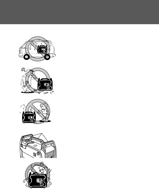
General safety information
• This generator is not designed for on-board use. |
1 |
Do not use it while installed on the vehicle. |
|
|
|
• Do not modify the generator or use it with its parts removed.
• Do not allow children to operate the generator.
• Be sure to carry the generator only by its carrying
1 |
handle. |
|
|
|
1. Carrying handle |
• Do not place any obstacles on the generator.
1-1
 Safety information
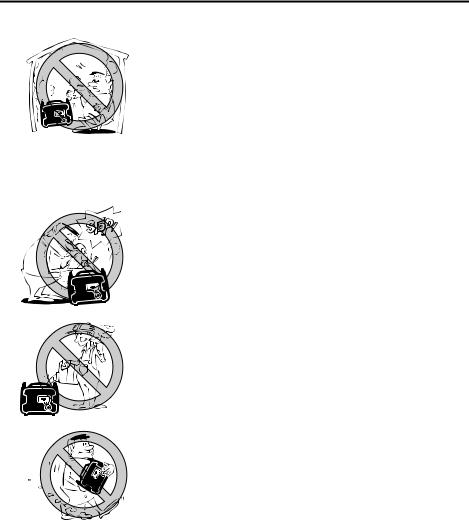
Exhaust fumes are poisonous
• Using a generator indoors CAN KILL YOU IN MINUTES. Generator exhaust contains carbon monoxide. This is a poison you cannot see or smell.
• NEVER use inside a home or garage, EVEN IF doors and windows are open.
• Only use OUTSIDE and far away from windows, doors, and vents.
Fuel is highly flammable and poisonous
• Always turn off the engine when refuelling.
• Never refuel while smoking or in the vicinity of an open flame.
• Take care not to spill any fuel on the engine or muffler when refueling.
• Do not leave the generator inside the vehicle or in the trunk.
• If you swallow any fuel, inhale fuel vapor, or allow any to get in your eye(s), see your doctor immediately. If any fuel spills on your skin or clothing, immediately wash with soap and water and change your clothes.
• When operating or transporting the generator, be sure it is kept upright. If it tilts, fuel may leak from the carburetor or fuel tank.
1-2

 Safety information
Engine and muffler may be hot
•Place the generator in a place where pedestrians or children are not likely to touch the machine.
•Avoid placing any flammable materials near the exhaust outlet during operation.
•In order to prevent overheating, ensure adequate airflow by keeping the machine at least 1 m (3 ft) from objects or other equipment.
•Do not operate the engine with a dust cover or other objects covering it.
•When covering the generator, be sure to do so only after the engine and muffler have completely cooled down.
Electric shock prevention
• Never operate the engine in rain or snow.
1-3
 Safety information
1
2
1
2
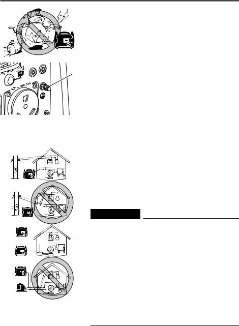
•Never touch the generator with wet hands or electrical shock will occur.
• Connect the ground (earth) terminal to a ground
1source. In order to prevent electrical shock, the generator must be grounded when using an electrical device with a ground plug.
1. Ground (earth) terminal
Connection notes
•Avoid connecting the generator to commercial power outlet.
•Avoid connecting the generator in parallel with any other generator.
1.Correct
2.Incorrect
Connection
 WARNING
Before the generator can be connected to a building’s electrical system, a licensed electrician must install an isolation (transfer) switch in the building’s main fuse box. The switch is the connection point for generator power and allows selection of generator or main line power to the building. This will prevent the generator from charging the main power line (backfeeding) when the main power supply has failed or has been turned off for line repair. Backfeeding can electrocute or injure line maintenance personnel. Also, generator and building electrical system damage can occur when normal operating power returns if unit is used without an isolation switch.
1-4
 Safety information
Extension cord notes
Extension cords should be protected by a tough flexible rubber sheath (IEC 245) or the equivalent to withstand mechanical stresses.
1-5

 Safety information
Location of important labels
Please read the following labels carefully before operating this machine.
TIP
Maintain or replace safety and instruction labels, as necessary.
4
1


2 |
|
5 |
|
|
|
|
9 |
6 |
|
|
|
|
8 |
|
3 |
|
7 |
|
|
1 3
2 |
4 |
5
1-6

 Safety information
6 |
9 |
|
|
|
|
|
|
|
|
|
|
|
|
|
|
|
|
|
|
|
|
|
|
|
|
|
|
|
|
|
|
|
|
|
|
|
|
|
|
|
|
|
|
|


 ****
****
************
************ |
************ |
7
8
EF2200iS
AC output 60Hz Rated 1.8kVA
120V Phase Single
DC output 12V 3A Fuel Gasoline
7PC-F4164-10
1-7
Controls and features
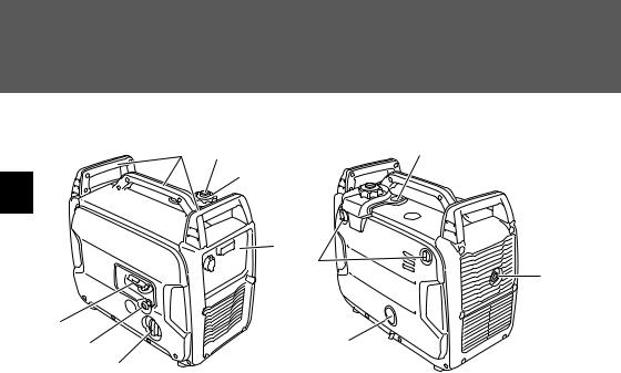
Description
|
1 |
2 |
8 |
|
|
3 |
|
2 |
|
|
|
|
|
|
4 |
|
|
|
11 |
|
|
|
9 |
7 |
|
|
|
|
6 |
|
10 |
|
5 |
|
|
1 |
Carrying handle (p. 1-1) |
|
7 Recoil starter (p. 2-9) |
2 |
Fuel tank cap air vent lever (p. 2-6) |
8 Fuel level gauge (p. 2-7) |
|
3 |
Fuel tank cap (p. 2-5) |
|
9 Muffler (p. 5-8) |
4 |
Control panel (p. 2-1) |
|
10 Carburetor fuel drain cock (p. 2-9) |
5 |
Engine switch (p. 2-4) |
|
11 Panel opener (p. 3-2) |
6 |
Choke knob (p. 4-1) |
|
|
2-1
Controls and features
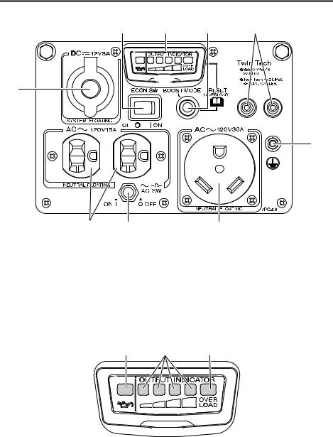
Control panel
2 |
3 |
|
|
4 |
5 |
|||
|
|
|
|
|
|
|
|
|
|
|
|
|
|
|
|
|
|
|
|
|
|
|
|
|
|
|
|
|
|
|
|
|
|
|
|
|
|
|
|
|
|
|
|
|
|
|
|
|
|
|
|
|
|
1
6
7 8
1Accessory socket (p. 2-9)
2Economy control switch (p. 2-5)
3Multi-function LED meter (p. 2-1)
4Boost mode switch/Reset button (p. 2-7/p. 2-6)
7
5Twin Tech (parallel running terminal) (p. 2-8)
6Ground (earth) terminal (p. 2-5)
7AC receptacle (p. 2-9)
8AC switch (N.F.B.) (p. 2-4)
Multi-function LED meter
1 |
2 |
3 |
1 |
Oil level warning light (Red) (p. 2-4) |
3 |
Overload indicator light (Red) (p. 2-6) |
2 |
Output indicator (Green) (p. 2-6) |
|
|
2-2
Controls and features
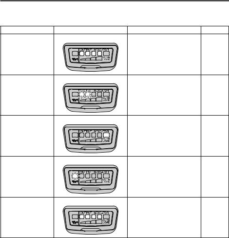
This generator has an integrated multi-function LED meter. Its functions are described as below.
Function |
Display |
Description |
Page |
|
|
Output indicator(s) come on |
|
Power supply meter |
|
according to the current power |
2-6 |
|
|
supply. |
|
|
|
Output indicator(s) flash ac- |
|
Operating time meter |
|
cording to the accumulated |
2-7 |
|
|
operation time. |
|
|
|
Overload indicator light comes |
|
|
|
on after output indicators |
|
Overload warning |
|
come on, when an overload or |
2-6 |
|
|
some malfunctions of connect- |
|
|
|
ed devices are detected. |
|
|
|
Oil level warning light flashes |
|
Oil warning |
|
when the engine oil level is too |
2-4 |
|
|
low. |
|
|
|
Output indicators come on |
|
Boost mode |
|
consecutively when the gener- |
2-7 |
|
|
ator is in boost mode. |
|
2-3
Controls and features
 2
2
1 |
3 |
1
1
Control function
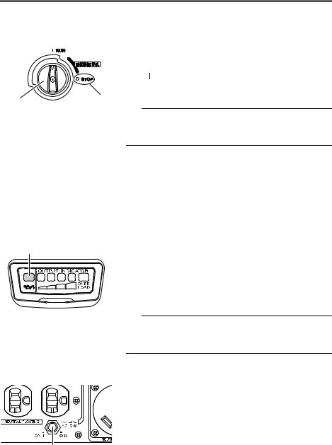
Engine switch
The engine switch controls the ignition system and the fuel cock.
1.Engine switch
2.“ ” (RUN)
3.“ ” (STOP)
TIP
The engine switch of this generator opens and closes the fuel cock simultaneously. You don’t need to operate the fuel cock separately.
“ ” (RUN)
Ignition circuit is switched on, and the fuel cock opens. The engine can be started.
“ ” (STOP)
Ignition circuit is switched off, and the fuel cock closes. The engine will not run.
Oil level warning light (Red)
When the oil level falls below the lower level, the oil level warning light flashes and then the engine stops automatically. If the light flashes, stop the engine immediately, and add engine oil up to the specified level.
Unless you refill with oil, the engine will not start again.
1. Oil level warning light (Red)
TIP
If the oil level warning light flashes even though the engine oil level is sufficient, make sure to place the generator horizontally.
AC switch (N.F.B.)
The AC switch (Non-Fuse Breaker) turns off automatically when the load exceeds the generator rated output.
1. AC switch (N.F.B.)
2-4

Controls and features
E
F
ON 
OFF |
1 |
1
3 |
2 |
1 |
NOTICE
Reduce the load to the specified generator rated output if the AC switch (N.F.B.) turns off. If it turns off again, consult a Yamaha dealer.
Fuel tank cap
Remove the fuel tank cap by turning it counterclockwise.
1. Fuel tank cap
Ground (earth) terminal
Ground (earth) terminal connects the earth line for prevention of electric shock.
When the electric device is grounded, be sure to ground the generator, too.
For the grounding, consult a Yamaha dealer.
1. Ground (earth) terminal
Economy control switch
In order to reduce fuel consumption and operating noise, use the economy control switch.
1.Economy control switch
2.“ ” (ON)
3.“ ” (OFF)
“

 ” (ON)
When the economy control switch is turned to “ ” (ON), the economy control unit regulates the engine speed according to the connected load. The results are better fuel consumption and less noise.
“

 ” (OFF)
When the economy control switch is turned to “ ” (OFF), the engine runs at the rated speed (4900 r/min) regardless of whether a load is connected or not.
TIP
•The economy control switch must be turned to “ ” (OFF) when using electric devices that require a
2-5

1
1


 2
2
|
|
E |
|
|
F |
3 |
|
1 |
4 |
OFF |
2 |
|
Controls and features
large starting current, such as a compressor of a submersible pump.
•Economy control does not function when the generator is in warming-up period (See page 4-1).
Power supply display
The current power supply level is displayed by the output indicators. According to the power supply level, the output indicator(s) will come on.
1. Output indicator (Green)
Overload indicator light (Red)
The overload indicator light comes on when electricity over the rated output is required by the connected electrical devices, or when the inverter control unit overheats, or the AC output voltage rises. Then the AC protector will trip, stopping power generation in order to protect the generator and any connected electric devices.
1.Overload indicator light (Red)
2.Reset button
TIP
The overload indicator light may come on for a few seconds at the first when using electric devices that require a large starting current, such as a compressor of a submersible pump. However, this is not a malfunction.
Fuel tank cap air vent lever
The fuel tank cap is provided with an air vent lever to stop fuel flow.
The air vent lever must be turned to “ON” to run the engine.
1.Air vent lever
2.Fuel tank cap
3.“ON”
4.“OFF”
2-6
Loading...