


CM-10-V
Table of contents
 Loading...
Yamaha CM-10-V, CM-12-V, CM-15-V, CW-115-V, CW-118-V Service manual
...
SPECIFICATIONS & DIMENSIONS ........................................ 3
NETWORK ................................................................................ 4
WIRE HARNESS .................................................................... 10
DISASSEMBLY PROCEDURE ............................................... 11
C112V/C115V ....................................................................... 11
C112VA/C115VA .................................................................. 14
C215V ................................................................................... 16
CM10V .................................................................................. 19
CM12V/CM15V .................................................................... 22
CW115V/CW118V ................................................................ 25
CW218V ............................................................................... 28
C112VA/C115VA(分解手順) ............................................ 30
NEUTRIK NL4FC PLUG WIRING
(スピコンNEUTRIKNL4FCプラグの配線)......................... 32
PARTS LIST
SERVICE MANUAL
CONTENTS
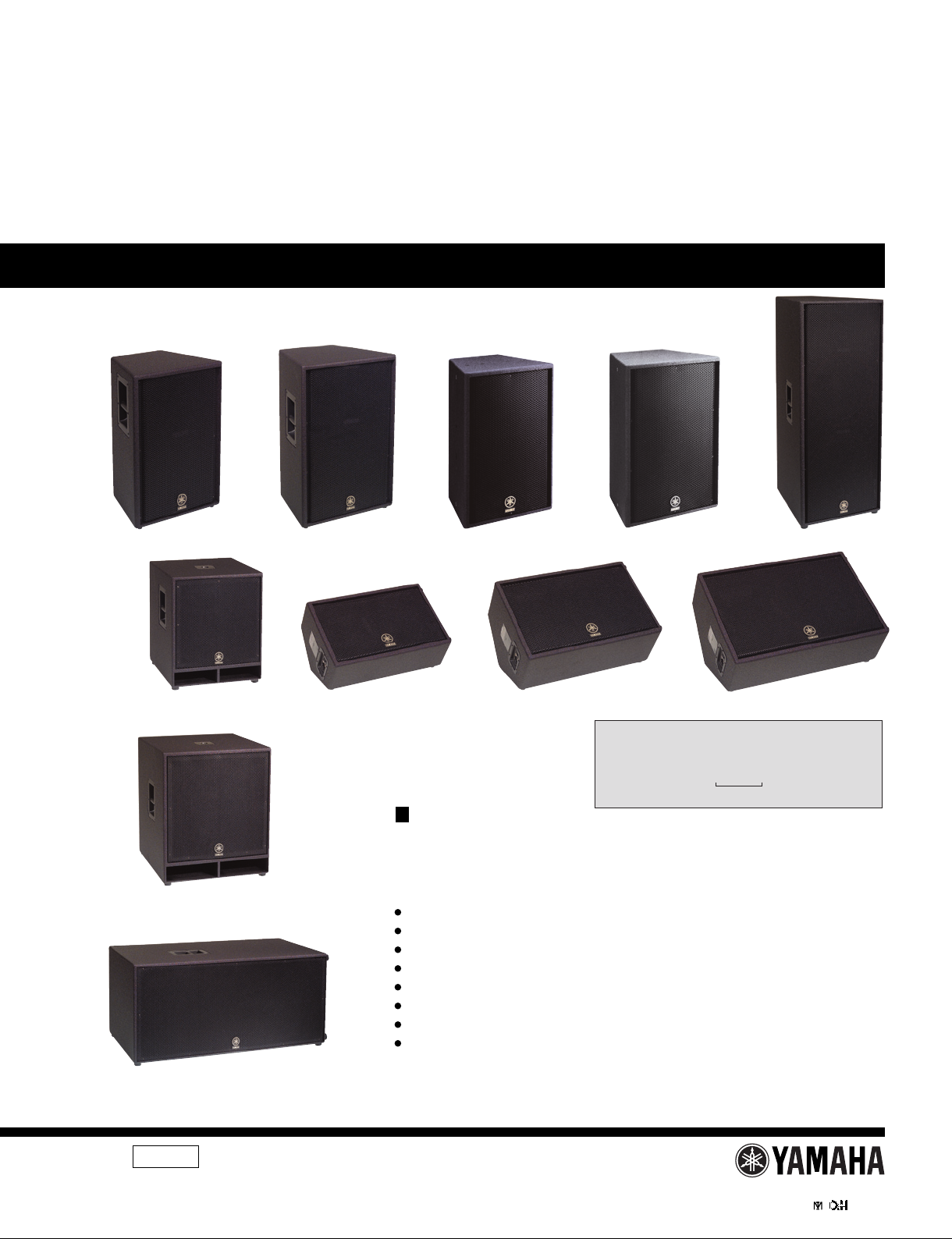
CLUB Series SPEAKER SYSTEM/
SUBWOOFER
C112V C115V C215V
CM10V CM12V CM15VCW115V
CW118V
CW218V
C112VA C115VA
PA
011868
Copyright (c) Yamaha Corporation. All rights reserved. PDF
’07.07
HAMAMATSU, JAPAN
Use this manual for products with a serial number of 7 figures.
(本マニュアルは、製造番号が7桁の商品でご使用ください。)
An example of a serial number
(製造番号例)
NK01089
7figures
(7桁)
S112VA: 200706 オープンプライス
S115VA: 200706 オープンプライス

2
CLUB Series
SPEAKER SYSTEM/
SUBWOOFER
IMPORTANT NOTICE
This manual has been provided for the use of authorized Yamaha Retailers and their service personnel. It has been assumed that basic
service procedures inherent to the industry, and more specifically Yamaha Products, are already known and understood by the users,
and have therefore not been restated.
WARNING : Failure to follow appropriate service and safety procedures when servicing this product may result in personal injury,
destruction of expensive components and failure of the product to perform as specified. For these reasons, we advise
all Yamaha product owners that all service required should be performed by an authorized Yamaha Retailer or the
appointed service representative.
IMPORTANT : This presentation or sale of this manual to any individual or firm does not constitute authorization certification,
recognition of any applicable technical capabilities, or establish a principal-agent relationship of any form.
The data provided is belived to be accurate and applicable to the unit(s) indicated on the cover. The research engineering, and service
departments of Yamaha are continually striving to improve Yamaha products. Modifications are, therefore, inevitable and changes in
specification are subject to change without notice or obligation to retrofit. Should any discrepancy appear to exist, please contact the
distributor’s Service Division.
WARNING : Static discharges can destroy expensive components. Discharge any static electricity your body may have accumulated
by grounding yourself to the ground bus in the unit (heavy gauge black wires connect to this bus.)
IMPORTANT : Turn the unit OFF during disassembly and parts replacement. Recheck all work before you apply power to the unit.
WARNING: CHEMICAL CONTENT NOTICE!
The solder used in the production of this product contains LEAD. In addition, other electrical/electronic and/or plastic (Where applicable)
components may also contain traces of chemicals found by the California Health and Welfare Agency (and possibly other entities) to cause
cancer and/or birth defects or other reproductive harm.
DO NOT PLACE SOLDER, ELECTRICAL/ELECTRONIC OR PLASTIC COMPONENTS IN YOUR MOUTH FOR ANY REASON WHAT SO EVER!
Avoid prolonged, unprotected contact between solder and your skin! When soldering, do not inhale solder fumes or expose eyes to solder/
flux vapor!
If you come in contact with solder or components located inside the enclosure of this product, wash your hands before handling food.
WARNING
Components having special characteristics are marked and must be replaced with parts having specification equal to those
originally installed.
印の部品は、安全を維持するために重要な部品です。交換する場合は、安全のために必ず指定の部品をご使用ください。
Poly Switch
All full-range loudspeakers are fitted with a self-resetting
poly switch that protects the high-frequency driver from
damage caused by excessive power.
If a loudspeaker cabinet loses high-frequency output, imme-
diately remove power from the unit and wait for two to three
minutes. They should allow the poly switch to reset. Re-
apply power and check the performance of the high-fre-
quency driver before continuing with the power reduced to a
level that does not cause the poly switch to interrupt the sig-
nal.
On the CW115V/CW118V/CW218V sub woofer, the Poly
Switch protects the woofer and a similar routine should be
followed if its output is lost.
3
CLUB Series
SPEAKER SYSTEM/
SUBWOOFER
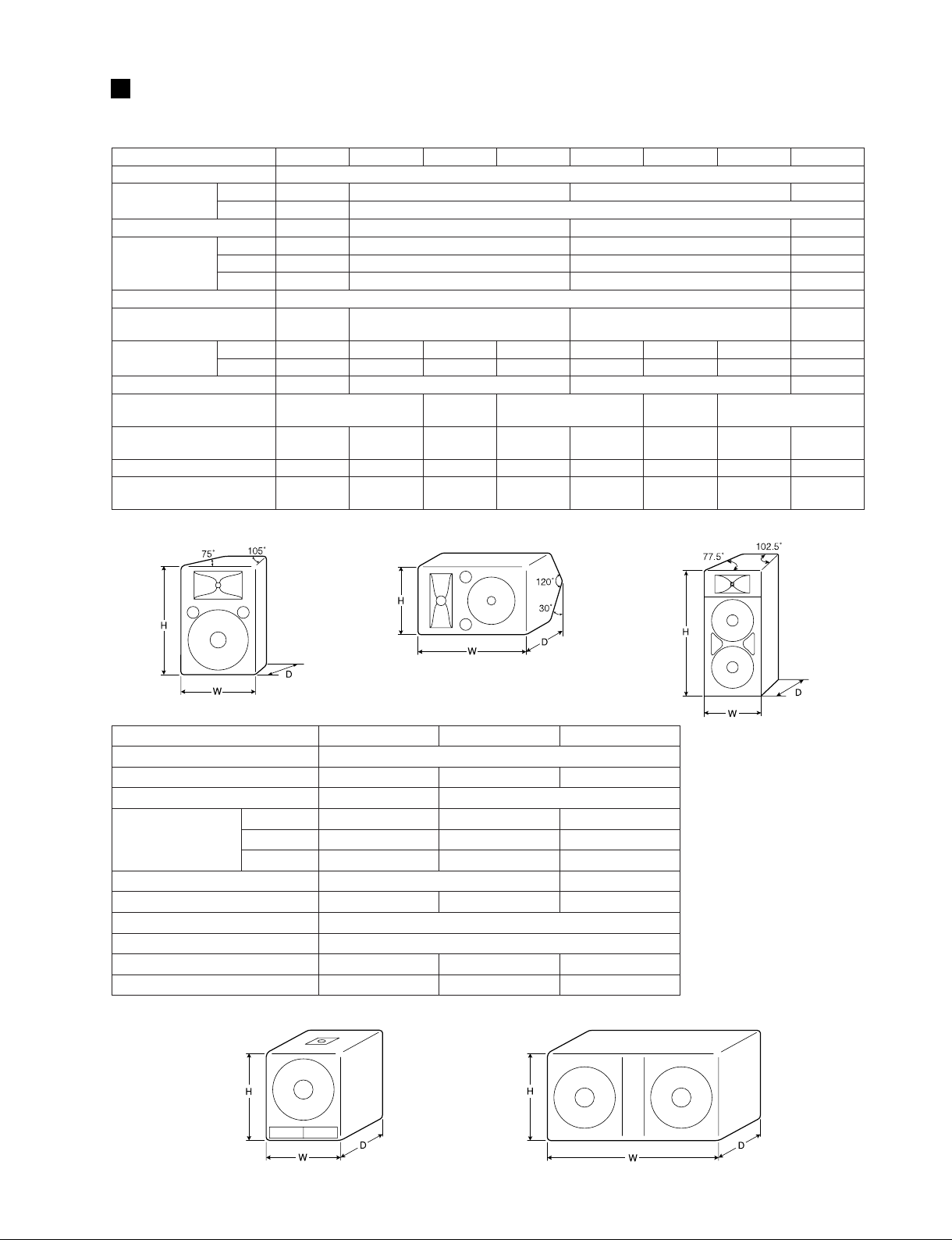
SPECIFICATIONS & DIMENSIONS
Model CM10V C112V C112VA CM12V C115V C115VA CM15V C215V
Enclosure
Bass Reflex Type
Speaker Unit
LF
10" cone 12" cone 15" cone 15" cone × 2
HF
1" V.C.driver 2" V.C.driver
Frequency Response
70Hz-20kHz 60Hz-16kHz 55Hz-16kHz 42Hz-16kHz
Power Capacity
NOISE*
125W 175W 250W 500W
PGM
250W 350W 500W 1000W
MAX
500W 700W 1000W 2000W
Nominal Impedance
8Ω 4Ω
Sensitivity
96dB SPL
(1W, 1m)
97dB SPL (1W, 1m) 99dB SPL (1W, 1m)
99dB SPL
(1W, 1m)
Nominal Dispersion
Horizontal
40˚ 90˚ 90˚ 40˚ 90˚ 90˚ 40˚ 90˚
Vertical
60˚ 40˚ 40˚ 90˚ 40˚ 40˚ 90˚ 40˚
Crossover Frequency
1.8kHz 2kHz 1.7kHz 1.5kHz
Input Connectors
1/4" Phone Jack × 2,
Neutrik Speakon NL4MP × 2
Barrier Strip
Terminal
1/4" Phone Jack × 2,
Neutrik Speakon NL4MP × 2
Barrier Strip
Terminal
1/4" Phone Jack × 2,
Neutrik Speakon NL4MP × 2
Dimensions (W ×H × D)
556 × 349
× 273mm
416 × 628
× 329mm
416 × 620
× 329mm
628 × 410
× 339mm
485
× 715
× 373mm
485 × 707
× 373mm
715 × 479
× 339mm
491 × 1163
× 593mm
Weight
13.3Kg 21.3Kg 21.8Kg 21.8Kg 30.3Kg 29.9Kg 28.8Kg 47.5Kg
Included Accessories
——
Eyebolt
(3/8") 4
——
Eyebolt
(3/8") 4
——
Model CW115V CW118V CW218V
Enclosure
Bass Reflex Type
Speaker Unit
15" cone 18" cone 18" cone
×
2
Frequency Response
35Hz-2kHz 30Hz-2kHz
Power Capacity
NOISE*
250W 300W 600W
PGM
500W 600W 1200W
MAX
1000W 1200W 2400W
Nominal Impedance
8
Ω
4
Ω
Sensitivity
95dB SPL (1W, 1m) 96dB SPL (1W, 1m) 98dB SPL (1W, 1m)
Recommended Crossover Frequency
90Hz, 12dB/oct.
Input Connectors
1/4" Phone Jack
×
2, Neutrik Speakon NL4MP
×
2
Dimensions (W
×
H
×
D)
500
×
607
×
528
mm
605
×
720
×
637
mm
1217
×
574
×
655
mm
Weight
28Kg 37.2Kg 64.7Kg
C112V/C112VA /C115V/C115VA CM10V/CM12V/CM15V C215V
CW115V/CW118V CW218V
Unit: mm
*: EIA RS-426

4
CLUB Series
SPEAKER SYSTEM/
SUBWOOFER
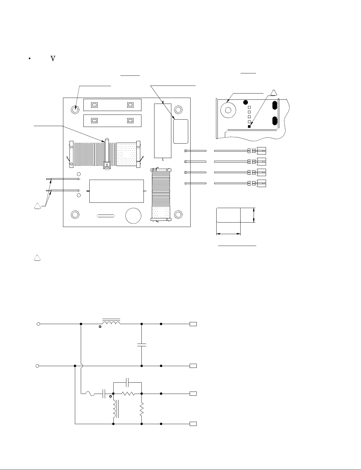
NETWORK
L1
X0.020
205
PLACE LABEL
APPROXIMATELY
WHERE SHOWN
EYELET
(4 PLACES)
CABLE TIE
(1 PLACE)
(0.50)
(0.80)
SPACER
(4 PLACES)
20mm
BLACK
SHRINK
TUBE
DETAIL
BLACK SHRINK TUBE- 4 PLACES
EYELET
(4 PLACES)
REAR
4'' WHITE
-
IN
X0.015
-
IN
-
IN
+ IN
-
IN
+ IN
+ IN
4'' ORANGE
+ IN
C2,C3 4.7UF, 250V, METALIZED POLYESTER FILM
L1 1.30mH, 57x9.5x10mm, LAMINATED STEEL I CORE
L2 0.80mH, 41x6x7mm, LAMINATED STEEL I CORE
R1,R2 5.00ohm, 10W
CL1 CURRENT LIMITER, RXE-135
C1 15UF, 100V, NON-POLAR
205
+T2
205
-T1
-W
205
+W
205
L2
CL1 C2
R1
C3
20" BLACK
20" BLUE
20" YELLOW
R2
20" RED
C1
187
187
X0.015
205
X0.020
X0.015
205
X0.020
X0.015
187
X0.020
187
205
10'' ORANGE
10'' ORANGE
4'' ORANGE
10'' WHITE
10'' WHITE
4'' WHITE
NBY0731
NBY0732
NBY0734
NBY0735
NBY0730
205
205
205
205
20'' BLUE
20'' YELLOW
20'' RED
20'' BLACK
LABEL DETAIL
SCALE:NONE
187 x .015
187 x .015
4'' WHITE
10'' WHITE
10'' ORANGE
4'' ORANGE
187 x .015
187 x .015
-IN
+IN
PARTIAL STRIPPED, 8m/m, NO TIN.
INDICATE MODEL BY A BLACK DOT.
APPLY RTV SEALANT UNDER C2,C3,L1,L2 AND HALF CIRCUMFERENCE AROUND C1.
''O'' DENOTES START LEAD OF INDUCTOR.
ALL COMPONENTS TO BE TESTED AT 1 KHZ UNLESS OTHERWISE SPECIFIED.
3.
2.
1.
CL1
+IN
-
IN
C2
L2
C1
+W
-
W
T2
T1
R1
R2
L1
C3
12
FRONT
12
a
5.
4.
4.
5.
C112 /CM12 (WJ367900)

5
CLUB Series
SPEAKER SYSTEM/
SUBWOOFER
PLACE LABEL
APPROXIMATELY
WHERE SHOWN
EYELET
(4 PLACES)
CL1
CABLE TIE
(1 PLACE)
+IN
-
IN
C2
R1
R2
L2
C1
L1
+W
-
W
T2
T1
C3
15
187 x .015 187 x .015
4'' WHITE
10'' WHITE
187 x .015 187 x .015
10'' ORANGE
4'' ORANGE
-IN
+IN
INDICATE MODEL BY A BLACK DOT.
APPLY RTV SEALANT UNDER C2,C3,L1,L2 AND HALF CIRCUMFERENCE AROUND C1.
''O'' DENOTES START LEAD OF INDUCTOR.
ALL COMPONENTS TO BE TESTED AT 1 KHZ UNLESS OTHERWISE SPECIFIED.
3.
2.
1.
NOTES:
C1 15UF, 100V, NON-POLAR
C2,C3 4.7UF, 250V, METALIZED POLYESTER FILM
L1 2.00mH
L2 0.80mH
R1,R2 8.20ohm, 10W
CL1 CURRENT LIMITER, RXE-135
205
205
205
205
20'' BLUE
20'' YELLOW
20'' RED
20'' BLACK
15
(0.50)
(0.80)
LABEL DETAIL
SCALE:NONE
FRONT
REAR
NBY0731
NBY0732
NBY0734
NBY0735
SPACER
(4 PLACES)
4.
20mm
BLACK
SHRINK
TUBE
DETAIL
NBY0730
205
+T2
L2
CL1 C2
R1
C3
L1
20" BLACK
20" BLUE
20" YELLOW
R2
205
-T1
-W
205
20" RED
C1
+W
205
X0.020
10'' ORANGE
10'' ORANGE
4'' WHITE
4'' ORANGE
10'' WHITE
10'' WHITE
4'' WHITE
BLACK SHRINK TUBE- 4 PLACES
-
IN
187
X0.015
-
IN
-
IN
187
X0.015
205
X0.020
X0.015
+ IN
-
IN
205
X0.020
X0.015
187
+ IN
+ IN
X0.020
187
205
4'' ORANGE
+ IN
205
PARTIAL STRIPPED, 8m/m, NO TIN.
5.
5.
4.
C115 /CM15 (WJ367800)

6
CLUB Series
SPEAKER SYSTEM/
SUBWOOFER
5.
4.
5.
4.
PLACE LABEL
APPROXIMATELY
WHERE SHOWN
EYELET
(4 PLACES)
CABLE TIE
(1 PLACE)
FRONT
REAR
SPACER
(4 PLACES)
20mm
BLACK
SHRINK
TUBE
DETAIL
(0.50)
(0.80)
BLACK SHRINK TUBE- 4 PLACES
-
IN
R1
R2
187 x .015
187 x .015
4'' WHITE
10'' WHITE
187 x .015
187 x .015
10'' ORANGE
4'' ORANGE
-IN
+IN
PARTIAL STRIPPED, 8m/m, NO TIN.
MARK PC BOARD WITH A BLACK DOT TO INDICATE MODEL.
APPLY RTV SEALANT UNDER C2,C3,L1,L2 AND HALF CIRCUMFERENCE AROUND C1.
''O'' DENOTES START LEAD OF INDUCTOR.
ALL COMPONENTS TO BE TESTED AT 1 KHZ UNLESS OTHERWISE SPECIFIED.
3.
2.
1.
NOTES:
+IN
205
110
205
205
LABEL DETAIL
SCALE:NONE
NBY0731
NBY0732
NBY0734
NBY0735
NBY0730
+W
-
W
T2
T1
15'' BLUE
15'' YELLOW
15'' RED
15'' BLACK
10
-
IN
-
IN
-
IN
+ IN
-
IN
+ IN
+ IN
+ IN
X0.020
10'' ORANGE
10'' ORANGE
4'' WHITE
4'' ORANGE
10'' WHITE
10'' WHITE
4'' WHITE
187
X0.015
187
X0.015
205
X0.020
X0.015
205
X0.020
X0.015
187
X0.020
187
205
4'' ORANGE
205
L1
15" RED
+W
205
110
+T2
L2
CL1 C2
R1
C3
15" BLACK
15" BLUE
15" YELLOW
R2
205
-T1
-W
205
C1 15UF, 100V, NON-POLAR
C2 8UF, 250V, METALIZED POLYESTER FILM
C3 4.7UF, 250V, METALIZED POLYESTER FILM
L1 1.80mH, 57x9.5x10mm, LAMINATED STEEL I CORE
L2 0.70mH, 41x6x7mm, LAMINATED STEEL I CORE
R1 6.80ohm, 10W
R2 3.90ohm, 10W
CL1 CURRENT LIMITER, RXE-135
C1
CL1
C2
L2
C1
L1
C3
10
CM10 (WJ368000)

7
CLUB Series
SPEAKER SYSTEM/
SUBWOOFER
PARTS LIST
C1 15uF, 250V, METALIZED POLYESTER FILM
C2 3.9uF, 250V, METALIZED POLYESTER FILM
C3 10 uF, 250V, METALIZED POLYESTER FILM
L1 5.00mH, 76x13x13mm, LAMINATED STEEL I CORE
L2 2.00mH,57x9.5x10mm, LAMINATED STEEL I CORE
L3 0.80mH,41x6x7xmm, LAMINATED STEEL I CORE
R1 3.90ohm, 10W
R2 10.0ohm, 10W
CL1 CURRENT LIMITER, RXE-135
CL1
L3
C2
L2
R1
R2
-
T
-
WU
+T
+WU
C3
L1
C1
+ WL
- WL
0.00
2.393
5.857
6.25
0.00
0.393
3.857
4.25
CABLE TIE
(2 PLACES)
S215-V
NBY0733
SPACER
(6 PLACES)
EYELET
(6 PLACES)
1.
2.
3.
4.
5.
NOTES:
APPLY RTV SEALANT UNDER C1,C2,C3,L1,L2, AND L3.
C1 & C3 STAND UP ON ONE SIDE. C2 LAYS DOWN FLAT.
''O'' DENOTES START LEAD OF INDUCTOR.
ALL COMPONENTS TO BE TESTED AT 1 KHZ UNLESS OTHERWISE SPECIFIED.
PARTIAL STRIPPED, 8m/m, NO TIN.
30'' BLUE
28'' BLACK
28'' RED/BLACK
30'' YELLOW
205
205
205
205
31'' BLACK
31'' RED
205
205
+IN
187 x
0.015
20mm
187 x
0.015
-IN
187 x
0.015
187 x
0.015
10'' ORANGE
4'' ORANGE
10'' WHITE
4'' WHITE
BLACK SHRINK TUBE- 4 PLACES
BLACK
SHRINK
TUBE
DETAIL
-
IN
+IN
10" ORANGE
187
+ IN
10" WHITE
" WHITE
" ORANCE
-
IN
-
IN
205
X 0.020
205
X 0.020
+ IN 187
X 0.015
X 0.015
C2
CL1
L3
R1
C3
L2
L1
31" RED
+WL
205
30" YELLOW
R2
30" BLUE
+
T
205
-T
205
28" BLACK
28" RED/BLACK
31" BLACK
C1
205
+WU
-
WU
205
-
WL
205
X0.020
10'' ORANGE
+ IN
205
4'' ORANGE
+ IN
205
X0.020
4'' WHITE
187
X0.015
10'' WHITE
-
IN
-
IN
187
X0.015
.
C215 (WJ368100)
8
CLUB Series
SPEAKER SYSTEM/
SUBWOOFER
PLACE LABEL
APPROXIMATELY
WHERE SHOWN
EYELET
(4 PLACES)
CL1
CABLE TIE
(1 PLACE)
+IN
-
IN
C2
R1
R2
L2
L1
+W
-
W
T2
T1
C3
12
TINNED 10m/m
MARK PC BOARD WITH A BLACK DOT TO INDICATE MODEL.
APPLY RTV SEALANT UNDER C2,C3,L1,L2 AND HALF CIRCUMFERENCE AROUND C1.
''O'' DENOTES START LEAD OF INDUCTOR.
ALL COMPONENTS TO BE TESTED AT 1 KHZ UNLESS OTHERWISE SPECIFIED.
5.
4.
3.
2.
1.
NOTES:
205
205
205
205
20'' BLUE
20'' YELLOW
20'' RED
20'' BLACK
12
(0.50)
(0.80)
LABEL DETAIL
SCALE:NONE
FRONT
REAR
NBY0731
NBY0732
NBY0734
NBY0735
SPACER
(4 PLACES)
4
NBY0730
10'' ORANGE
+ IN
- IN
10'' WHITE
C3
C2CL1
L2
R1
L1
20" RED
20" YELLOW
R2
20" BLUE
205
+T2
205
-T1
20" BLACK
C1
-W
205
+W
205
C1 15UF, 100V, NON-POLAR
C2,C3 4.7UF, 250V, METALIZED POLYESTER FILM
L1 1.30mH, 57x9.5x10mm, LAMINATED STEEL I CORE
L2 0.80mH, 41x6x7mm, LAMINATED STEEL I CORE
R1,R2 5.00ohm, 10W
CL1 CURRENT LIMITER, RXE-135
10'' WHITE
10'' ORANGE
5.
C1
C112 A (WJ368200)

9
CLUB Series
SPEAKER SYSTEM/
SUBWOOFER
APPROXIMATELY
WHERE SHOWN
EYELET
(4 PLACES)
CL1
CABLE TIE
(1 PLACE)
+IN
-
IN
C2
R1
R2
L2
C1
L1
+W
-
W
T2
T1
C3
15
TINNED 10m/m
MARK PC BOARD WITH A BLACK DOT TO INDICATE MODEL.
APPLY RTV SEALANT UNDER C2,C3,L1,L2 AND HALF CIRCUMFERENCE AROUND C1.
''O'' DENOTES START LEAD OF INDUCTOR.
ALL COMPONENTS TO BE TESTED AT 1 KHZ UNLESS OTHERWISE SPECIFIED.
5.
4.
3.
2.
1.
NOTES:
205
205
205
205
20'' BLUE
20'' YELLOW
20'' RED
20'' BLACK
15
(0.50)
(0.80)
LABEL DETAIL
SCALE:NONE
FRONT
REAR
NBY0731
NBY0732
NBY0734
NBY0735
SPACER
(4 PLACES)
4
NBY0730
C1 15UF, 100V, NON-POLAR
C2,C3 4.7UF, 250V, METALIZED POLYESTER FILM
L1 2.00mH, 57x9.5x10mm, LAMINATED STEEL I CORE
L2 0.80mH, 41x6x7mm, LAMINATED STEEL I CORE
R1,R2 8.20ohm, 10W
CL1 CURRENT LIMITER, RXE-135
10'' ORANGE
+ IN
- IN
10'' WHITE
C3
C2CL1
L2
R1
L1
20" RED
20" YELLOW
R2
20" BLUE
205 +T2
205
-T1
20" BLACK
C1
-W205
+W205
10'' WHITE
10'' ORANGE
5.
C115 A (WJ368300)
10
CLUB Series
SPEAKER SYSTEM/
SUBWOOFER
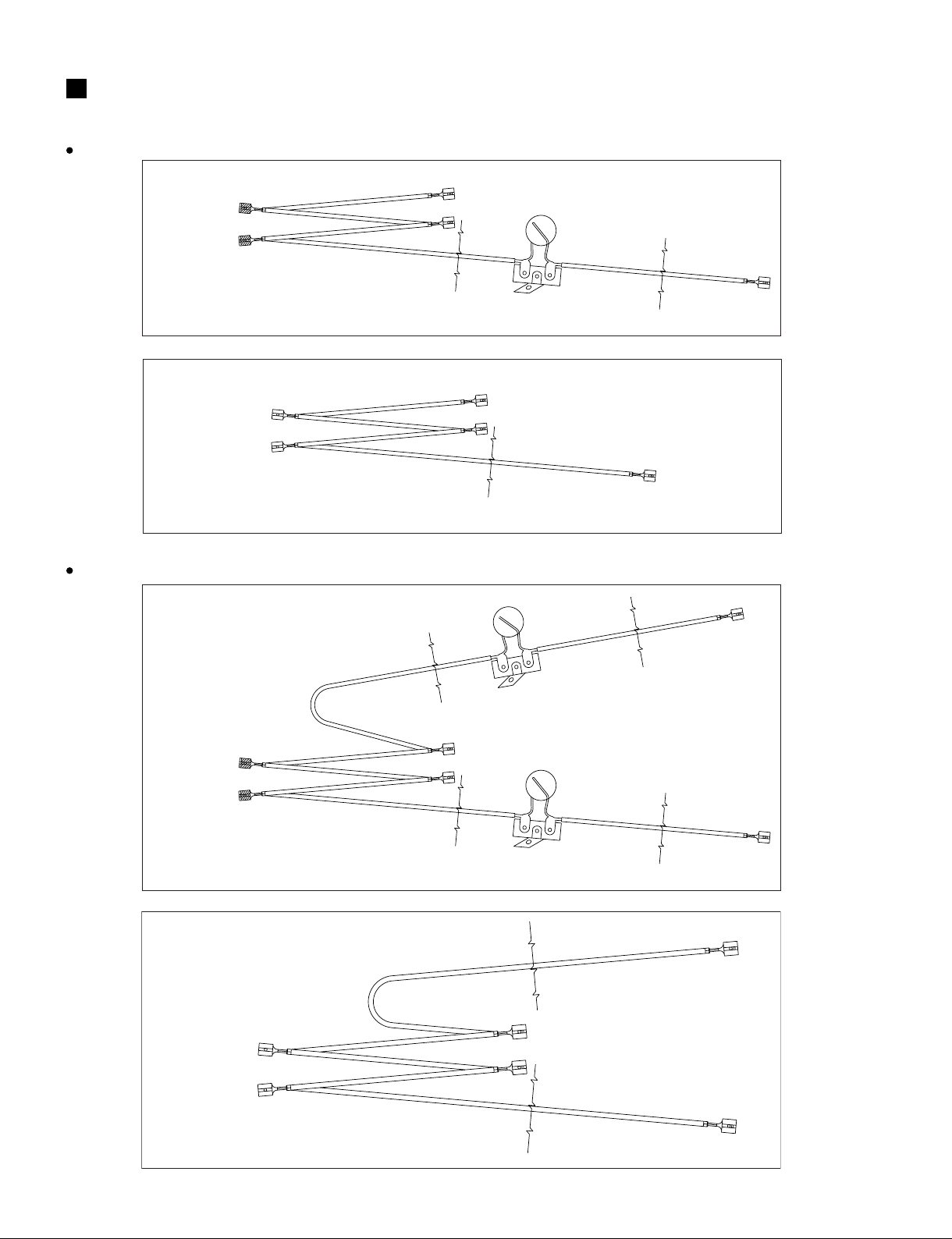
ORANGE WIRE, 16 AWG, PACIFICA
L = 20"
L = 20"
L = 20"
L = 4" X 3
0.187 X 0.015
FASTON + HEAT
SHRINK
X 2
RXE-250
RXE-250
0.205 X 0.020
FASTON
X 4
WIRE HARNESS A
WJ500200
WOOFER (+)
WOOFER (+)
Polyswitch
Polyswitch
0.187 X 0.015
FASTON
X 2
ORANGE WIRE, 16 AWG, PACIFICA
WIRE HARNESS A
WJ419900
L = 20"
L = 20"
L = 4" X 3
0.187 X 0.015
FASTON + HEAT
SHRINK
X 2
WOOFER (+)
RXE-250
Polyswitch
0.187 X 0.015
FASTON
0.205 X 0.020
FASTON
X 3
WHITE WIRE, 16 AWG, PACIFICA
L = 40"
L = 4" X 3
0.187 X 0.015
FASTON + HEAT
X 2
0.205 X 0.020
FASTON
X 3
WIRE HARNESS B
(WJ42000)
WOOFER (--)
0.187 X 0.015
FASTON
WHITE WIRE, 16 AWG, PACIFICA
L = 30"
L = 30"
L = 4" X 3
0.187 X 0.015
FASTON
X 2
0.205 X 0.020 FASTON
X 4
WIRE HARNESS B
(WJ50030)
WOOFER (--)
WOOFER (--)
0.187 X 0.015
FASTON
X 2
CW115V, CW118V
WIRE HARNESS
CW218V
11
CLUB Series
SPEAKER SYSTEM/
SUBWOOFER
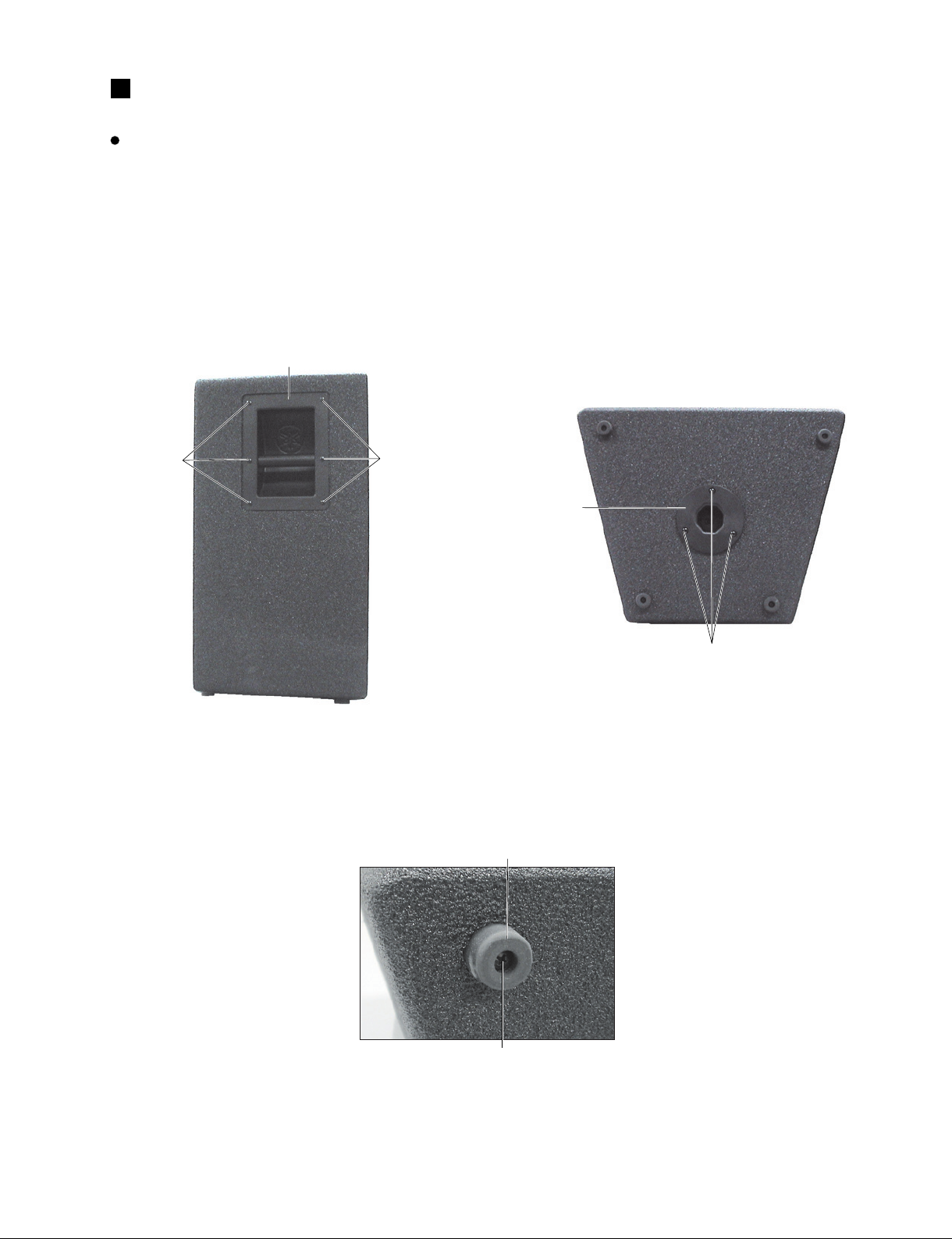
[10d]
Rubber foot
[160]
[160]
Metal handle
[130A]
Pole socket
Photo 1
[160]: TH SMS Screw #8 x 3/4 BLACK (WJ911600)
Photo 3
Photo 2
DISASSEMBLY PROCEDURE
C112V/C115V
1. Metal Handle (Time required: About 1 minute)
1-1 Remove the six (6) screws marked [160]. The metal
handle can then be removed. (Photo 1)
2. Pole Socket (Time required: About 1 minutes)
2-1 Remove the three (3) screws marked [130A]. The
Pole Socket can then be removed. (Photo 2)
3. Rubber Foot (Time required: About 1 minutes)
3-1 Remove the screw marked [10d]. The rubber foot
can then be removed. (Photo 3)
[130]: Pan Head PB Screw #10 x 1 BLK (WJ911300)
[10d]: Pan Head PB Screw #10 x 1 BLK (WJ911300)

12
CLUB Series
SPEAKER SYSTEM/
SUBWOOFER
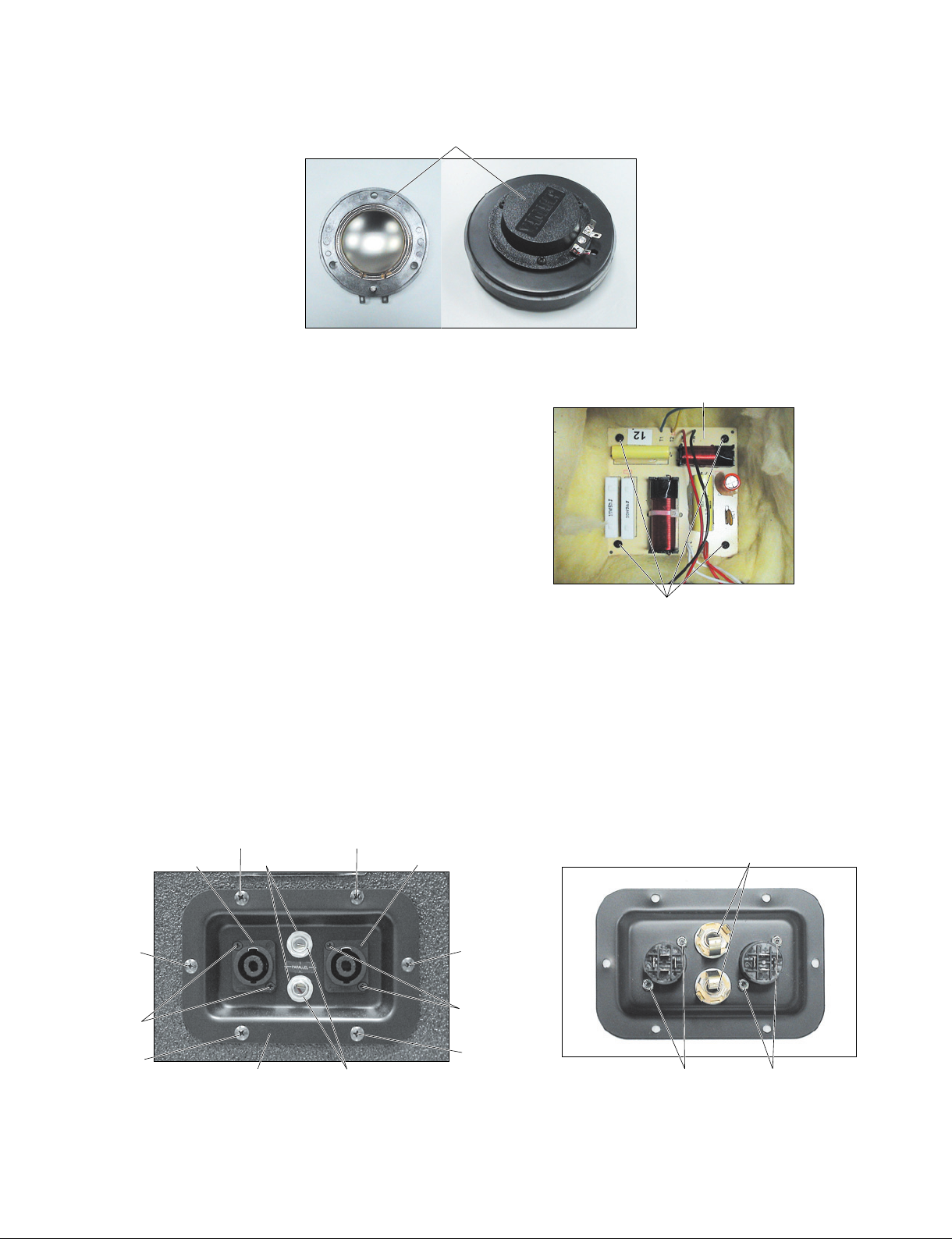
[150]
[150]
Woofer
[150]
[130B][130B]
Horn assembly
[50c]
Horn
Horn driver
[A]
Diaphragm assembly
Horn
Horn driver
[140A]
[140A]
[140A]
[140A]
[140A]
Metal grille assembly
Photo 6
Photo 4
Photo 5
4. Woofer (Time required: About 3 minutes)
4-1 Remove the eight (8) screws marked [140A]. The
Metal grille assembly can then be removed. (Photo 4)
4-2 Remove the eight (8) screws marked [150]. The
woofer can then be removed. (Photo 5)
Photo 7
5. Horn Assembly
(Time required: About 3 minutes)
5-1 Remove the Metal grille assembly.
(See procedure 4-1)
5-2 Remove the eight (8) screws marked [130B]. The
horn assembly can then be removed. (Photo 5)
5-3 Horn
5-3-1 Remove the two (2) hex head mach screw marked
[50c]. The horn can then be removed from the horn
assembly. (Photo 7)
5-4 Diaphragm Assembly
5-4-1 Remove the three (3) screws marked [A]. The
diaphragm assembly can then be removed from the
horn driver. (Photo 6, 8)
[140]: TH Sheet Metal Screw #6 x 5/8 BLK (WJ493800)
[130]: Pan Head PB Screw #10 x 1 BLK (WJ911300)
C112V
[150]: Pan Head PB Screw PHPBS #8 x 1 BLK (WJ911500)
C115V
[150]: Pan HD Machine Screw #10-32 x 1 BLK (WJ494200)
[50c]: Hex Head Mach Screw 1/4 x 5/8 inch (WJ356300)
13
CLUB Series
SPEAKER SYSTEM/
SUBWOOFER
Photo 9
Photo 8
6. Network (Time required: About 4 minutes)
6-1 Remove the woofer. (See procedure 4)
6-2 Remove the four (4) screws marked [170]. The
network can then be removed. (Photo 9)
Diaphragm assembly
Network
[170]
Photo 10
Photo 11
7. Input Assembly
(Time required: About 2 minutes)
7-1 Remove the six (6) screws marked [140B]. The input
assembly can then be removed. (Photo 10)
7-2 Remove the two (2) screws marked [90f] and the
two (2) hexagonal nuts marked [90e]. The connector
NL4MP can then be removed. (Photo 10, 11)
[140B]
[140B]
[140B]
[140B]
[140B]
[90f]
[90f]
Input assembly
[140B]
Connector NL4MP Connector NL4MP
Hexagonal nut
Plain washer
[90e] [90e]
Phone jack
7-3 Remove the hexagonal nut. The plain washer and
phone jack can then be removed. (Photo 10, 11)
[170]: Pan Head SM Screw PHSMS #6 x 3/4 BLK (WJ911700)
[90e]: Hexagonal Nut #4-40 NYLOK NUT (WJ372000)[90f]: FH Machining Screw #4-40 x 3/8 ZN BL (WJ372100)
[140]: TH Sheet Metal Screw #6 x 5/8 BLK (WJ493800)

14
CLUB Series
SPEAKER SYSTEM/
SUBWOOFER
[140A]
[140A]
[140A]
[140A]
[140A]
Metal grille assembly
[150]
[150]
Woofer
[150]
[130]
[130]
Horn assembly
[50c]
Horn
Horn driver
[A]
Diaphragm assembly
Horn
Horn driver
Photo 4Photo 3
C112VA/C115VA
Photo 1
Photo 2
1. Woofer (Time required: About 3 minutes)
1-1 Remove the eight (8) screws marked [140A]. The
metal grille assembly can then be removed. (Photo 1)
2. Horn Assembly
(Time required: About 3 minutes)
2-1 Remove the metal grille assembly. (See procedure 1-1)
2-2 Remove the eight (8) screws marked [130]. The horn
assembly can then be removed. (Photo 2)
2-3 Horn
2-3-1 Remove the two (2) hex head mach screw marked
[50c]. The horn can then be removed from the horn
assembly. (Photo 4)
1-2 Remove the eight (8) screws marked [150]. The
woofer can then be removed. (Photo 2)
2-4 Diaphragm Assembly
2-4-1 Remove the three (3) screws marked [A]. The
diaphragm assembly can then be removed from the
horn driver. (Photo 3, 5)
[50c]: Hex Head Mach Screw 1/4 x 5/8 inch (WJ356300)
[140]: TH Sheet Metal Screw #6 x 5/8 BLK (WJ493800) [130]: Pan Head PB Screw #10 x 1 BLK (WJ911300)
C112VA
[150]: Pan Head PB Screw PHPBS #8 x 1 BLK (WJ911500)
C115VA
[150]: Pan HD Machine Screw #10-32 x 1 BLK (WJ494200)
15
CLUB Series
SPEAKER SYSTEM/
SUBWOOFER
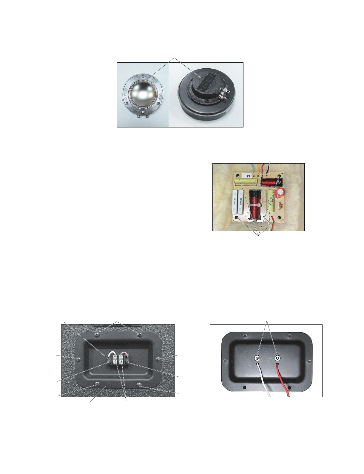
[140B]
[140B]
[140B]
[140B]
[140B]
[90c]
[B]
[90c]
Input assembly
Barrier strip
[90d]
Photo 6
Photo 5
3. Network (Time required: About 4 minutes)
3-1 Remove the woofer. (See procedure 1)
3-2 Remove the four (4) screws marked [170]. The
network can then be removed. (Photo 6)
Diaphragm assembly
Network
[170]
Photo 7
Photo 8
4. Input Assembly
(Time required: About 2 minutes)
4-1 Remove the six (6) screws marked [140B]. The input
assembly can then be removed. (Photo 7)
4-2 Remove the two (2) screws marked [90c], the two (2)
keps nuts marked [90d] and the solder marked [B].
The barrier strip can then be removed. (Photo 7, 8)
[170]: Pan Head SM Screw PHSMS #6 x 3/4 BLK (WJ911700)
[90d]: Keps Nut #6-32 (WJ542400)
[90c]: Pan HD Machine Screw PHMS #6-32 x 1/2 ZN BLK (WJ971600)
[140]: TH Sheet Metal Screw #6 x 5/8 BLK (WJ493800)
16
CLUB Series
SPEAKER SYSTEM/
SUBWOOFER
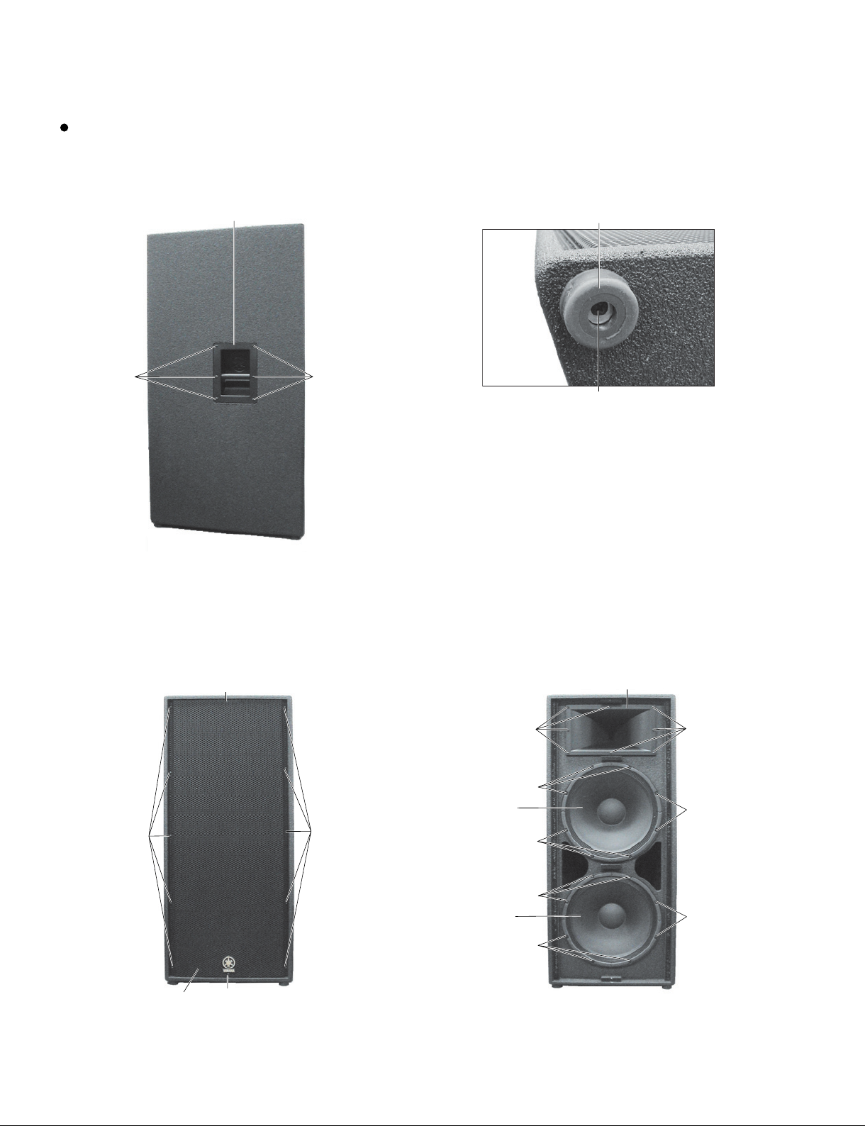
[130A]
[130A]
[130A]
Metal grille assembly
[130A]
Woofer
Woofer
[170]
[170]
[170]
[170]
[170]
[170]
[140]
[140]
Horn assembly
Photo 3 Photo 4
[150]
[150]
Metalhandle(メタルハンドル)
Photo 1
Photo 2
[10d]
Rubber foot
3. Woofer (Time required: About 5 minutes)
3-1 Remove the twelve (12) screws marked [130A]. The
metal grille assembly can then be removed. (Photo 3)
C215V
1. Metal Handle (Time required: About 1 minute)
1-1 Remove the six (6) screws marked [150]. The metal
handle can then be removed. (Photo 1)
2. Rubber Foot (Time required: About 1 minutes)
2-1 Remove the screw marked [10d]. The rubber foot
can then be removed. (Photo 2)
3-2 Remove the eight (8) screws marked [170]. The
woofer can then be removed. (Photo 4)
[150]: TH SMS Screw #8 x 3/4 BLACK (WJ911600)
[10d]: Pan Head PB Screw #10 x 1 BLK (WJ911300)
[130]: TH Sheet Metal Screw #6 x 5/8 BLK (WJ493800)
[140]: Pan HD Machine Screw #10-32 x 1 BLK (WJ494200)
[170]: Pan HD Machine Screw #10-32 x 1-1/2 (WJ624200)

17
CLUB Series
SPEAKER SYSTEM/
SUBWOOFER
[A]
Diaphragm assembly
Horn
Horn driver
Photo 5
Photo 6
[50c]
Horn
Horn driver
Diaphragm assembly
Photo 7
4. Horn Assembly
(Time required: About 3 minutes)
4-1 Remove the metal grille assembly. (See procedure 3-1)
4-2 Remove the eight (8) screws marked [140]. The horn
assembly can then be removed. (Photo 4)
4-3 Horn
4-3-1 Remove the two (2) hex head mach screw marked
[50c]. The horn can then be removed from the horn
assembly. (Photo 6)
4-4 Diaphragm Assembly
4-4-1 Remove the three (3) screws marked [A]. The
diaphragm assembly can then be removed from the
horn driver. (Photo 5, 7)
[50c]: Hex Head Mach Screw 1/4 x 5/8 inch (WJ356300)
Loading...