


HF/50 MHZ TRANSCEIVER
FT-950
OPERATING MANUAL
VERTEX STANDARD CO., LTD.
4-8-8 Nakameguro, Meguro-Ku, Tokyo 153-8644, Japan
VERTEX STANDARD
US Headquarters
10900 Walker Street, Cypress, CA 90630, U.S.A.
YAESU UK LTD.
Unit 12, Sun Valley Business Park, Winnall Close
Winchester, Hampshire, SO23 0LB, U.K.
VERTEX STANDARD HK LTD.
Unit 5, 20/F., Seaview Centre, 139-141 Hoi Bun Road,
Kwun Tong, Kowloon, Hong Kong
VERTEX STANDARD (AUSTRALIA) PTY., LTD.
Normanby Business Park, Unit 14/45 Normanby Road Notting Hill 3168, Victoria, Australia

ABOUT THIS MANUAL . . .
The FT-950 is a leading-edge transceiver with a number of new and exciting features, some of which may be unfamiliar to you. In order to gain the most enjoyment and operating efficiency from your FT-950, we recommend that you read this manual in its entirety, and keep it handy for reference as you explore the many capabilities of your new transceiver.
Before using your FT-950, be sure to read and follow the instructions in the “Before You Begin” section of this manual.

GENERAL DESCRIPTION
Congratulations on the purchase of your Yaesu amateur transceiver! Whether this is your first rig, or if Yaesu equipment is already the backbone of your station, rest assured your transceiver will provide many hours of operating pleasure for years to come.
The FT-950 is an elite-class HF transceiver providing exceptional performance both on transmit and receive. The FT-950 is designed for the most competitive operating situations, whether you primarily operate in contest, DX, or digital-mode environments.
Built on the foundation of the popular FTDX9000 transceiver, and carrying the proud tradition of the FT-1000 series, the FT-950 provides up to 100 Watts of power output on SSB, CW, and FM (25 Watts AM carrier). Digital Signal Processing (DSP) is utilized throughout the design, providing leading-edge performance, both transmit and receive.
The Data Management Unit (DMU-2000) is available as an option for the FT-950. It provides extensive display capabilities via a user-supplied computer monitor. Included are Band Scope, Audio Scope, X-Y Oscilloscope, World Clock, Rotator Control, extensive Transceiver Status Displays, and Station Logging Capability.
For exceptional protection from strong signal interference, the optional RF μTuning Kits may be connected via the rear panel. The μTuning Kits provide extraordinarily sharp selectivity, and protect your receiver from close-in interference on a crowded band.
In the front end, you may select one of two RF preamplifiers, or IPO (Intercept Point Optimization) providing direct feed to the first mixer. Three levels of RF attenuation are available in 6-dB steps.
The FT-950 receiver utilizes DSP filtering, incorporating many of the features of the FTDX9000, such as, Variable Bandwidth, IF Shift, and Passband Contour tuning. Also provided are Digital Noise Reduction, Digital Auto-Notch Filtering and a manually tuned IF Notch filter.
On the transmit side, the Yaesu-exclusive Three-Band Parametric Microphone Equalizer allows precise and flexible adjustment of the waveform created by your voice and microphone. The Amplitude, Center Frequency, and Bandwidth are adjusted separately for the low, mid-range, and high-frequency audio spectra. The transmitted bandwidth may also be adjusted.
Advanced features include: Direct Keyboard Frequency Entry and Band Change, Speech Processor, IF Monitor for Voice modes, CW Pitch control, CW Spot switch, Full CW QSK, adjustable IF Noise Blanker, and all-mode Squelch. Two TX/RX antenna ports are provided on the rear panel. Two key jacks are provided (one on the front and one on the rear panel). The key jacks may be configured independently for paddle input, connection to a straight key, or computer-driven keying interface. The CW Message Memory is provided.
Frequency setup is straightforward on the FT-950. Enter frequency directly for both VFO-A and VFO-B. Separate keys are provided for band selection. Each band key provides three separate VFO settings for three different parts of each band. You can establish three independent VFO settings of frequency, mode, and filter for each band.
In addition, 99 memories are provided to store: Frequency, Mode, IF filter selection, Clarifier offset, and Scan-skip status. What’s more, five quick-recall (“QMB”) memories can instantly store operational settings at the push of a button.
The built-in antenna tuner includes 100 memories that automatically store antenna matching settings for rapid automatic recall later.
Interfacing for digital modes is extremely simple with the FT-950, thanks to the dedicated RTTY/PKT connection jack on the rear panel. Optimization of the filter passband, DSP settings, carrier insertion point, and display offset for digital modes, is possible via the Menu programming system.
Advanced technology is only part of the FT-950 story. Vertex Standard stands behind our products with a worldwide network of dealers and service centers. We greatly appreciate your investment in the FT-950, and we look forward to helping you get the most out of your new transceiver. Please feel free to contact your nearest dealer, or one of Vertex Standard’s national headquarters offices, for technical advice, interfacing assistance, or accessory recommendation. Watch Vertex Standard U.S.A.’s Home Page for late-breaking information about Vertex, Standard Horizon, and Yaesu products: http://www.vertexstandard.com.
Please read this manual thoroughly, to gain maximum understanding of the full capability of the FT-950. We thank you again for your purchase!
FT-950 OPERATING MANUAL |
Page 1 |

TABLE OF CONTENTS
General Description ..................................................... |
1 |
Accessories & Options ................................................. |
4 |
Supplied Accessories ............................................... |
4 |
Available Options ..................................................... |
5 |
Before You Begin ......................................................... |
6 |
Extending the Front Feet .......................................... |
6 |
Adjusting the Main Tuning Dial Torque .................. |
6 |
Resetting the Microprocessor .................................. |
7 |
Resetting Memories (Only) ................................ |
7 |
Menu Resetting................................................... |
7 |
Full Reset ............................................................ |
7 |
Installation and Interconnections ............................... |
8 |
Antenna Considerations ........................................... |
8 |
About Coaxial Cable ................................................ |
8 |
Grounding ................................................................ |
9 |
Connection of Antenna and Power Cables ............. |
10 |
Connection of Microphone and Headphone .......... |
11 |
Key, Keyer, and Computer-Driven Keying |
|
Interconnections ..................................................... |
12 |
VL-1000 Linear Amplifier Interconnections.......... |
13 |
Interfacing to Other Linear Amplifiers ................... |
14 |
Plug/Connector Pinout Diagrams ............................ |
15 |
Front Panel Controls & Switches ............................. |
16 |
Display Indications .................................................... |
24 |
Rear Panel .................................................................. |
27 |
Basic Operation: Receiving on Amateur Bands ...... |
29 |
Operation on 60-Meter (5 MHz) Band |
|
(U.S. version only) ................................................. |
32 |
CLAR (Clarifier) Operation ................................... |
33 |
LOCK ..................................................................... |
34 |
DIMMER ............................................................... |
34 |
Convenience Features................................................ |
35 |
Using VFO-B ......................................................... |
35 |
“MY Bands” Operation .......................................... |
36 |
Band Stack Operation ............................................ |
37 |
C.S (Custom Switch) .............................................. |
37 |
Rotator Control Functions ...................................... |
38 |
More Frequency Navigation Techniques ............... |
39 |
Keyboard Frequency Entry .............................. |
39 |
Using the [CLAR/VFO-B] knob ...................... |
39 |
Using the UP/DOWN switches of |
|
the supplied MH-31B8 Hand Microphone ........ |
39 |
Interference Rejection ............................................... |
40 |
Receiver Operation (Front End Block Diagram) ... |
40 |
ATT ........................................................................ |
41 |
μ-Tune Filter .......................................................... |
42 |
IPO (Intercept Point Optimization) ........................ |
44 |
R.FLT (Roofing Filters) ......................................... |
45 |
IF Noise Blanker (NB) Operation .......................... |
46 |
CONTOUR Control Operation .............................. |
47 |
IF SHIFT Operation ............................................... |
48 |
WIDTH (IF DSP Bandwidth) Tuning .................... |
49 |
Using IF Shift and Width Together................... |
49 |
NARROW (NAR) One-Touch IF Filter Selection ... |
50 |
IF Notch Filter Operation....................................... |
51 |
Digital Notch Filter (DNF) Operation ................... |
52 |
Digital Noise Reduction (DNR) Operation ............ |
52 |
RF Gain (SSB/CW/AM Modes) ............................ |
53 |
Tools for Comfortable and Effective Reception ...... |
54 |
Audio Pitch Control ............................................... |
54 |
Mute Feature .......................................................... |
54 |
AGC (Automatic Gain Control) ............................. |
55 |
SSB/AM Mode Transmission .................................... |
56 |
Using the Automatic Antenna Tuner ........................ |
58 |
ATU Operation ....................................................... |
58 |
About ATU Operation ............................................ |
59 |
Enhancing Transmit Signal Quality ......................... |
60 |
Parametric Microphone Equalizer ......................... |
60 |
Using the Speech Processor ................................... |
62 |
Adjusting the SSB Transmitted Bandwidth ........... |
63 |
Transmitter Convenience Features .......................... |
64 |
Voice Memory ........................................................ |
64 |
Voice Memory Operation from |
|
the optional FH-2 Remote Control Keypad ..... |
65 |
VOX (Automatic TX/RX Switching using Voice Control) ............. |
66 |
MONITOR ............................................................. |
67 |
Split Operation Using the TX Clarifier .................. |
68 |
Split-Frequency Operation ..................................... |
69 |
Quick Split Operation ....................................... |
69 |
Page 2 |
FT-950 OPERATING MANUAL |

TABLE OF CONTENTS
CW Mode Operation ................................................. |
70 |
Setup for Straight Key |
|
(and Straight Key emulation) Operation ................ |
70 |
Using the Built-in Electronic Keyer ....................... |
71 |
Full Break-in (QSK) Operation ........................ |
72 |
Setting the Keyer Weight (Dot/Dash) Ratio...... |
72 |
Selecting the Keyer Operating Mode ............... |
73 |
CW Convenience Features ........................................ |
74 |
Audio Peak Filter ................................................... |
74 |
CW Spotting (Zero-Beating) .................................. |
74 |
Using CW Reverse ................................................. |
75 |
CW Delay Time Setting ......................................... |
76 |
CW Pitch Adjustment ............................................. |
76 |
Contest Memory Keyer .......................................... |
78 |
Message Memory ............................................. |
78 |
Transmitting in the Beacon Mode .............. |
79 |
TEXT Memory ................................................. |
80 |
Contest Number Programming ................... |
82 |
Contest Memory Keyer |
|
(Using the optional FH-2 Remote Control Keypad) ...... |
82 |
Message Memory ............................................. |
82 |
TEXT Memory ................................................. |
84 |
FM Mode Operation ................................................. |
87 |
Basic Operation ...................................................... |
87 |
Repeater Operation ................................................ |
88 |
Tone Squelch Operation ......................................... |
89 |
Memory Operation .................................................... |
90 |
Convenient Memory functions ............................... |
90 |
QMB (Quick Memory Bank) ................................. |
91 |
Standard Memory Operation .................................. |
92 |
Memory Storage ............................................... |
92 |
Memory Channel Recall ................................... |
92 |
Checking Memory Channel Status ................... |
93 |
Erasing Memory Channel Data ........................ |
93 |
Moving Memory Data to |
|
the Main Band (VFO-A) .................................. |
94 |
Memory Tune Operation .................................. |
94 |
Memory Groups ..................................................... |
95 |
Memory Group Assignment ............................. |
95 |
Choosing the Desired Memory Group ............. |
95 |
Operation on Alaska Emergency Frequency: |
|
5167.5 kHz (U.S. Version Only) ................................ |
96 |
VFO and Memory Scanning ..................................... |
97 |
VFO Scanning ........................................................ |
97 |
Memory Scan ......................................................... |
98 |
PMS (Programmable Memory Scan)....................... |
99 |
Packet Operation ..................................................... |
100 |
Packet Setup (Including Subcarrier Frequency) .. |
100 |
Basic Setup .......................................................... |
100 |
RTTY (Radio Teletype) Operation ......................... |
101 |
Setting Up for RTTY Operation ........................... |
101 |
Basic Setup .......................................................... |
101 |
Miscellaneous AFSK-Based Data Modes .............. |
102 |
About the Transverter Output Terminal ............... |
107 |
Menu Mode .............................................................. |
103 |
Using the Menu .................................................... |
103 |
Menu Mode Reset ................................................ |
103 |
AGC Group .......................................................... |
108 |
DISPLAY Group .................................................. |
108 |
DVS Group .......................................................... |
109 |
KEYER Group ..................................................... |
109 |
GENERAL Group ................................................ |
110 |
MODE-AM Group ............................................... |
111 |
MODE-CW Group ............................................... |
111 |
MODE-DATA Group ........................................... |
113 |
MODE-FM Group ............................................... |
113 |
MODE-RTTY Group ........................................... |
113 |
MODE-SSB Group .............................................. |
114 |
RX GENERAL Group ......................................... |
114 |
SCOPE Group ...................................................... |
115 |
TUNING Group ................................................... |
116 |
TX AUDIO Group ............................................... |
116 |
TX GNRL Group ................................................. |
118 |
Installation of the Optional Filter .......................... |
120 |
Voice Memory Unit (DVS-6) ............................... |
120 |
RF μTuning Kit .................................................... |
121 |
FC-40 External Automatic Antenna Tuner ........... |
122 |
Data Management Unit (DMU-2000) .................. |
124 |
Specifications............................................................ |
126 |
FT-950 OPERATING MANUAL |
Page 3 |

ACCESSORIES & OPTIONS
|
|
|
|
|
|
|
|
SUPPLIED ACCESSORIES |
|
|
|
Hand Microphone (MH-31B8) |
1 pc |
A07890001 |
DC Power Cord |
1 pc |
T9025225 |
Spare Fuse (25A) |
1 pc |
Q0000074 |
Operating Manual |
1 pc |
|
Warranty Card |
1 pc |
|
Page 4 |
FT-950 OPERATING MANUAL |

|
ACCESSORIES & OPTIONS |
|
|
|
|
|
|
|
AVAILABLE OPTIONS |
|
|
MD-200A8X |
Ultra-High-Fidelity Desktop Microphone |
MD-100A8X |
Desktop Microphone |
YH-77STA |
Lightweight Stereo Headphone |
VL-1000/VP-1000 |
Linear Amplifier/AC Power Supply |
DMU-2000 |
Data Management Unit |
RF μTuning Kit A |
For 160 m Band |
RF μTuning Kit B |
For 80/40 m Bands |
RF μTuning Kit C |
For 30/20 m Bands |
FC-40 |
External Automatic Antenna Tuner |
DVS-6 |
Voice Memory Unit |
FH-2 |
Remote Control Keypad |
CT-118 |
VL-1000 Linear Amplifire Connection Cable |
CT Cable (MDIN6P - MDIN6P 2m) |
Antenna Rotator Connection Cable (P/N T9101556) |
CT Cable (MDIN10P - Bare Wire 2m) Linear Amplifier Connection Cable (P/N T9207451)
MD-200A8X |
YH-77STA |
FH-2 |
VL-1000/VP-1000 |
DMU-2000 |
RF μTuning Kit |
FC-40 |
DVS-6 |
FT-950 OPERATING MANUAL |
Page 5 |
BEFORE YOU BEGIN
EXTENDING THE FRONT FEET
To elevate the front panel for easy viewing, the front left and right feet of the bottom case may be extended.
Pull the front legs outward from the bottom panel. Rotate the legs counter-clockwise to lock them in the extended position. Be sure the legs have locked securely in place, because the transceiver is quite heavy and an unlocked leg could result in damage, should the transceiver move suddenly.
Retracting the Front Feet
Rotate the legs clockwise, and push them inward while rotating to the right.
The front feet should now be locked in the retracted position.
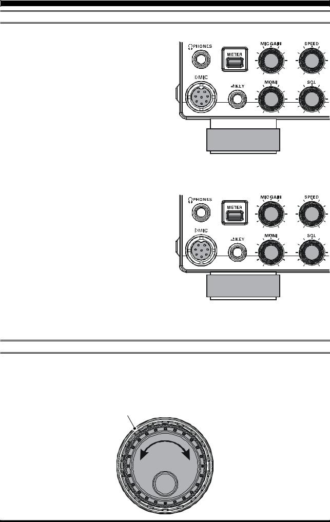
ADJUSTING THE MAIN TUNING DIAL TORQUE
The torque (drag) of the Main Tuning Dial knob may be adjusted according to your preferences. Simply hold down the rear skirt of the knob, and while holding it in place rotate the knob clockwise to reduce the drag or counterclockwise to increase the drag. Available adjustment range is 120°.
Hold the Skirt
TIGHTEN LOOSEN
Page 6 |
FT-950 OPERATING MANUAL |

BEFORE YOU BEGIN
RESETTING THE MICROPROCESSOR
RESETTING MEMORIES (ONLY)
Use this procedure to reset (clear) the previously stored Memory channels, without affecting any configuration changes you may have made to the Menu settings.
1.Press the front panel’s [POWER] switch to turn the transceiver off.
2.Press and hold in the [AXM] button; while holding it in, press and hold in the front panel’s [POWER] switch to turn the transceiver on. Once the transceiver comes on, you may release the buttons.
MENU RESETTING
Use this procedure to restore the Menu settings to their factory defaults, without affecting the memories you have programmed.
1.Press the front panel [POWER] switch to turn the transceiver off.
2.Press and hold in the [MENU] button; while holding it in, press and hold in the front panel [POWER] switch to turn the transceiver on. Once the transceiver comes on, you may release the buttons.
FULL RESET
Use this procedure to restore all Menu and Memory settings to their original factory defaults. All Memories will be cleared by this procedure.
1.Press the front panel [POWER] switch to turn the transceiver off.
2.Press and hold the [FAST] and [LOCK] buttons; while holding them in, press and hold in the front panel [POWER] switch to turn the transceiver on. Once the transceiver comes on, you may release the buttons.
IMPORTANT NOTE:
When the optional μTuning Kit is connected to the FT950, disconnect all the cables from the μTuning Kit before performing the Full Reset.
|
|
|
|
|
|
|
|
[POWER] button |
[AXM] button |
||
|
|
|
|
|
|
|
|
[POWER] button |
[MENU] button |
||
[FAST] button
|
|
|
|
|
|
|
|
|
|
|
|
|
|
|
|
|
|
|
|
[POWER] button |
[LOCK] button |
|||
FT-950 OPERATING MANUAL |
Page 7 |

INSTALLATION AND INTERCONNECTIONS
ANTENNA CONSIDERATIONS
The FT-950 is designed for use with any antenna system providing a 50 Ohm resistive impedance at the desired operating frequency. While minor excursions from the 50-Ohm specification are of no consequence, if the Standing Wave Ratio (SWR) present at the Antenna jack is greater than 3:1, the transceiver’s Automatic Antenna Tuner may not be able to reduce the impedance mismatch to an acceptable value.
Every effort should be made to ensure that the impedance of the antenna system be as close as possible to the specified 50Ohm value. Note that the “G5RV” type antenna does not provide a 50-Ohm impedance on all HF Amateur bands. An external wide-range antenna coupler must be used with this antenna type.
Any antenna to be used with the FT-950 must be fed from the transceiver with 50 Ohm coaxial cable. Therefore, when using a “balanced” antenna such as a dipole, remember that a balun or other matching/balancing device must be used to ensure proper antenna performance.
The same precautions apply to any additional (receive-only) antennas connected to the antenna jacks; if your receive-only antennas do not have impedance near 50 Ohms at the operating frequency, you may need to install an external antenna tuner to obtain optimum performance.
ABOUT COAXIAL CABLE
Use high-quality 50-Ohm coaxial cable for the lead-in to your FT-950 transceiver. All efforts at providing an efficient antenna system will be wasted if poor quality, lossy coaxial cable is used. This transceiver utilizes standard “M” (“PL-259”) type connectors.
1/16'' |
Adapter |
|
3/4'' |
|
3/4'' |
|
1 1/8'' |
1/8'' |
3/8'' 5/8''
TYPICAL PL-259 INSTALLATION
Page 8 |
FT-950 OPERATING MANUAL |
INSTALLATION AND INTERCONNECTIONS
GROUNDING
The FT-950 transceiver, like any other HF communications apparatus, requires an effective ground system for maximum electrical safety and best communications effectiveness. A good ground system can contribute to station efficiency in a number of ways:
It can minimize the possibility of electrical shock to the operator.
It can minimize RF currents flowing on the shield of the coaxial cable and the chassis of the transceiver; such currents may lead to radiation, which can cause interference to home entertainment devices or laboratory test equipment.
It can minimize the possibility of erratic transceiver/accessory operation caused by RF feedback and/or improper current flow through logic devices.
An effective earth ground system may take several forms; for a more complete discussion, see an appropriate RF engineering text. The information below is intended only as a guideline.
Typically, the ground connection consists of one or more copper-clad steel rods, driven into the ground. If multiple ground rods are used, they should be positioned in a “V” configuration, and bonded together at the base of the “V” which is nearest the station location. Use a heavy, braided cable (such as the discarded shield from type RG-213 coaxial cable), and strong cable clamps to secure the braided cable(s) to the ground rods. Be sure to weatherproof the connections to ensure many years of reliable service. Use the same type of heavy, braided cable for the connections to the station ground bus (described below).
Inside the station, a common ground bus consisting of a copper pipe of at least 25 mm (1”) diameter should be used. An alternative station ground bus may consist of a wide copper plate (single-sided circuit board material is ideal) secured to the bottom of the operating desk. Grounding connections from individual transceivers, power supplies, and data communications devices (TNCs, etc.) should be made directly to the ground bus using a heavy, braided cable.
Do not “Daisy-Chain” ground connections from one electrical device to another, and thence to the ground bus. This method may nullify any attempt at effective radio frequency grounding. See the drawing below for examples of proper grounding techniques.
Inspect the ground system - inside the station as well as outside - on a regular basis to ensure continued performance and safety.
Besides following the above guidelines carefully, note that household or industrial gas lines must never be used in an attempt to establish an electrical ground. Cold water pipes may, in some instances, help in the grounding effort, but gas lines represent a significant explosion hazard, and must never be used.
Transceiver |
Linear |
TNC |
Transceiver |
Linear |
TNC |
|
Amplifier |
|
|
Amplifier |
|
|
|
|
|
"Daisy Chain" |
|
PROPER GROUND CONNECTION |
IMPROPER GROUND CONNECTION |
||||
FT-950 OPERATING MANUAL |
Page 9 |
INSTALLATION AND INTERCONNECTIONS
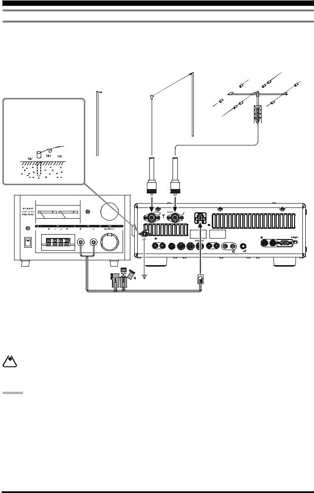
CONNECTION OF ANTENNA AND POWER CABLES
Please follow the outline in the illustration regarding the proper connection of antenna coaxial cables, as well as the DC power cable. The DC power connector for the FT-950 must only be connected to a DC source providing 13.8 Volts DC (±10 %), and capable of at least 22 Amperes of current. Always observe proper polarity when making DC connection:
The RED DC power lead connects to the Positive (+) DC terminal. The BLACK DC power lead connects to the Negative (–) DC terminal.
Use a short, thick, braided cable to connect your station equipment to the buried ground rod (or alternative earth ground system).
ANTENNA“1” |
ANTENNA“2” |
0 |
5 10 15 20 |
0 |
5 |
20 30 40 |
1 |
ANT |
2 |
DC IN |
|
V |
|
|
A |
OVERLOAD |
|
|
|
|
CONTINUOUS |
CURRENT |
25A |
|
|
|
INPUT: DC 13.8 V |
|
|
|
|
|
|
|
|
|
|
|
|
|
|
|
|
|
|
22 A |
POWER
ON
|
-TUNE |
|
|
|
EXT |
-TUNE DMU |
CAT |
GND |
TO FROM |
ROT LINEAR TUNER |
PTT REC |
REM |
SPKR |
KEY |
|
|
|
|
|
|
|
|
OFF
RED BLACK
BLACK
FUSE: 25A
We recommend the use of the FP-1030A AC Power Supply. Other models of power supplies may be used with the FT-950, but the 13.8 VDC input voltage, 22-Ampere current capability, and DC cable polarity guidelines described above must be strictly followed.
Note that other manufacturers may use the same type of DC power connections as does your FT-950 transceiver, however, the wiring configuration may be different from that specified for your transceiver. Serious damage can be caused if improper DC connections are made; consult with a qualified service technician when in doubt.
 Permanent damage can result when improper supply voltage, or reverse-polarity voltage, is applied to the FT-950.
  The Limited Warranty on this transceiver does not cover damage caused by application of AC voltage, reverse polarity DC, or DC voltage outside the specified range of 13.8 V ±10 %. When replacing fuses, be certain to use a fuse of
the proper rating. The FT-950 requires a 25 A blade fuse.
ADVICE:
Do not position the FT-950 in a location with direct exposure to sunshine.
Do not position the FT-950 in a location exposed to dust and/or high humidity.
Ensure adequate ventilation around the FT-950, to prevent heat build-up and possible reduction of performance due to high heat.
Do not install the FT-950 on an unstable desk or table. Do not place in a location where objects may fall onto it from above. To minimize the possibility of interference to home entertainment devices, take all precautionary steps including separation of TV/FM antennas from Amateur transmitting antennas to the greatest extent possible, and keep transmitting coaxial cables separated from cables connected to home entertainment devices.
Ensure that the DC power cord is not subject to undue stress or bending, which could damage the cable or cause it to be accidentally unplugged from the rear panel DC IN jack.
Be certain to install your transmitting antenna(s) so they cannot possibly come in contact with TV/FM radio or other antennas, or with power or telephone lines.
Page 10 |
FT-950 OPERATING MANUAL |
INSTALLATION AND INTERCONNECTIONS
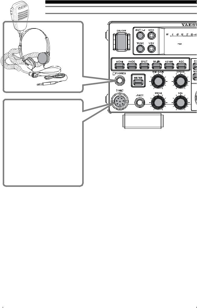
CONNECTION OF MICROPHONE AND HEADPHONE
|
|
|
|
|
|
|
|
|
|
|
|
|
|
|
|
|
|
|
|
|
|
|
|
|
|
|
|
|
|
|
|
|
|
|
|
|
|
|
|
|
|
|
|
|
|
|
|
|
|
|
|
|
|
|
|
|
|
|
|
|
|
|
|
|
|
|
|
|
|
|
|
|
|
|
|
|
|
|
|
|
|
|
|
|
|
|
|
|
|
|
|
|
|
|
|
|
|
|
|
|
|
|
|
|
|
|
|
|
|
|
|
|
|
|
|
|
|
|
|
|
|
|
|
|
|
|
|
|
|
|
|
|
|
|
|
|
|
|
|
|
|
|
|
|
|
|
|
|
|
|
|
|
|
|
|
|
|
|
|
|
|
|
|
|
|
|
|
|
|
|
|
|
|
|
|
|
|
|
|
|
|
|
|
|
|
|
|
|
|
|
|
|
|
|
|
|
|
|
|
|
|
|
|
|
|
|
|
|
|
|
|
|
|
|
|
|
|
|
|
|
|
|
|
|
|
|
|
|
|
|
|
|
|
|
|
|
|
|
|
|
|
|
|
|
|
|
|
|
|
|
|
|
|
|
|
|
|
|
|
|
|
|
|
|
|
|
|
|
|
|
|
|
|
|
|
|
|
|
|
|
|
|
|
|
|
|
|
|
|
|
|
|
|
|
|
|
|
|
|
|
|
|
|
|
|
|
|
|
|
|
|
|
|
|
|
|
|
|
|
|
|
|
|
|
|
|
|
|
|
|
|
|
|
|
|
|
|
|
|
|
|
|
|
|
|
|
|
|
|
|
|
|
|
|
|
|
|
|
|
|
|
|
|
|
|
|
|
|
|
|
|
|
|
|
|
|
|
|
|
|
|
|
|
|
|
|
|
|
|
|
|
|
|
|
|
|
|
|
|
|
|
|
|
|
|
|
|
|
|
|
|
|
|
|
|
|
|
|
|
|
|
|
|
|
|
|
|
|
|
|
|
|
|
|
|
|
|
|
|
|
|
|
|
|
|
|
|
|
|
|
|
|
|
|
|
|
|
|
|
|
|
|
|
|
|
|
|
|
|
|
|
|
|
|
|
|
|
|
|
|
|
|
|
|
|
|
|
|
|
|
|
|
|
|
|
|
|
|
|
|
|
|
|
|
|
|
|
|
|
|
|
|
|
|
|
|
|
|
|
|
|
|
|
|
|
|
|
|
|
|
|
|
|
|
|
|
|
|
|
|
|
|
|
|
|
|
|
|
|
|
|
|
|
|
|
|
|
|
|
|
|
|
|
|
|
|
|
|
|
|
|
|
|
|
|
|
|
|
|
|
|
|
|
|
|
|
|
|
|
|
|
|
|
|
|
|
|
|
|
|
|
|
|
|
|
|
|
|
|
|
|
|
|
|
|
|
|
|
|
|
|
|
|
|
|
|
|
|
|
|
|
|
|
|
|
|
|
|
|
|
|
|
|
|
|
|
|
|
|
|
|
|
|
|
|
|
|
|
|
|
|
|
|
|
|
|
|
|
|
|
|
|
|
|
|
|
|
|
|
|
|
|
|
|
|
|
|
|
|
|
|
|
|
|
|
|
|
|
|
|
|
|
|
|
|
|
|
|
|
|
|
|
|
|
|
|
|
|
|
|
|
|
|
|
|
|
|
|
|
|
|
|
|
|
|
|
|
|
|
|
|
|
|
|
|
|
|
|
|
|
|
|
|
|
|
|
|
|
|
|
|
|
|
|
|
|
|
|
|
|
|
|
|
|
|
|
|
|
|
|
|
|
|
|
|
|
|
|
|
|
|
|
|
|
|
|
|
|
|
|
|
|
|
|
|
|
|
|
|
|
|
|
|
|
|
|
|
|
|
|
|
|
|
|
|
|
|
|
|
|
|
|
|
|
|
|
|
|
|
|
|
|
|
|
|
|
|
|
|
|
|
|
|
|
|
|
|
|
|
|
|
|
|
|
|
|
|
|
|
|
|
|
|
|
|
|
|
|
|
|
|
|
|
|
|
|
|
|
|
|
|
|
|
|
|
|
|
|
|
|
|
|
|
|
|
|
|
|
|
|
|
|
|
|
|
|
|
|
|
|
|
|
|
|
|
|
|
|
|
|
|
|
|
|
|
|
|
|
|
|
|
|
|
|
|
|
|
|
|
|
|
|
|
|
|
|
|
|
|
|
|
|
|
|
|
|
|
|
|
|
|
|
|
|
|
|
|
|
|
|
|
|
|
|
|
|
|
|
|
|
|
|
|
|
|
|
|
|
|
|
|
|
|
|
|
|
|
|
|
|
|
|
|
|
|
|
|
|
|
|
|
|
|
|
|
|
|
|
|
|
|
|
|
|
|
|
|
|
|
|
|
|
|
|
|
|
|
|
|
|
|
|
|
|
|
|
|
|
|
|
|
|
|
|
|
|
|
|
|
|
|
|
|
|
|
|
|
|
|
|
|
|
|
|
|
|
|
|
|
|
|
|
|
|
|
|
|
|
|
|
|
|
|
|
|
|
|
|
|
|
|
|
|
|
|
|
|
|
|
|
|
|
|
|
|
|
|
|
|
|
|
|
|
|
|
|
|
|
|
|
|
|
|
|
|
|
|
|
|
|
|
|
|
|
|
|
|
|
|
|
|
|
|
|
|
|
|
|
|
|
|
|
|
|
|
|
|
|
|
|
|
|
|
|
|
|
|
|
|
|
|
|
|
|
|
|
|
|
|
|
|
|
|
|
|
|
|
|
|
|
|
|
|
|
|
|
|
|
|
|
|
|
|
|
|
|
|
|
|
|
|
|
|
|
|
|
|
|
|
|
|
|
|
|
|
|
|
|
|
|
|
|
|
|
|
|
|
|
|
|
|
|
|
|
|
|
|
|
|
|
|
|
|
|
|
|
|
|
|
|
|
|
|
|
|
|
|
|
|
|
|
|
|
|
|
|
|
|
|
FT-950 OPERATING MANUAL |
|
|
|
|
|
|
|
|
|
|
|
|
|
|
|
|
|
|
|
|
|
|
|
|
Page 11 |
||||||||||||||||||||||||||

INSTALLATION AND INTERCONNECTIONS
KEY, KEYER, AND COMPUTER-DRIVEN KEYING INTERCONNECTIONS
The FT-950 includes many features for the CW operator. These functions will be detailed in the “Operation” section later. Besides the built-in Electronic Keyer, two key jacks are provided, one on the front and one on the rear panel, for convenient connection to keying devices.
The Menu selections allow you to configure the front and rear panel KEY jacks according to the device you wish to connect. For example, you may connect your keyer paddle to the front panel KEY jack, and use Menu item “037 A1A F- TYPE” for paddle input, and also connect the keying line from your personal computer (which emulates a “straight key”), to the rear panel KEY jack, and configure the rear panel jack using Menu item “039 A1A R-TYPE”.
Both KEY jacks on the FT-950 utilize “Positive” keying voltage. Key-up voltage is approximately +3.3V DC, and keydown current is approximately 0.3 mA. When connecting a key or other device to the KEY jacks, use only a 3-contact (“stereo”) 1/4” phone plug; a 2-contact plug will place a short between the ring and (grounded) shaft of the plug, resulting in a constant “key-down” condition in some circumstances.
-TUNE DMU |
CAT |
KEY
|
|
|
|
|
|
|
|
|
|
|
|
|
|
|
|
|
|
|
|
|
|
|
|
|
|
|
|
|
|
|
|
|
|
|
Page 12 |
|
|
|
FT-950 OPERATING MANUAL |
||
INSTALLATION AND INTERCONNECTIONS
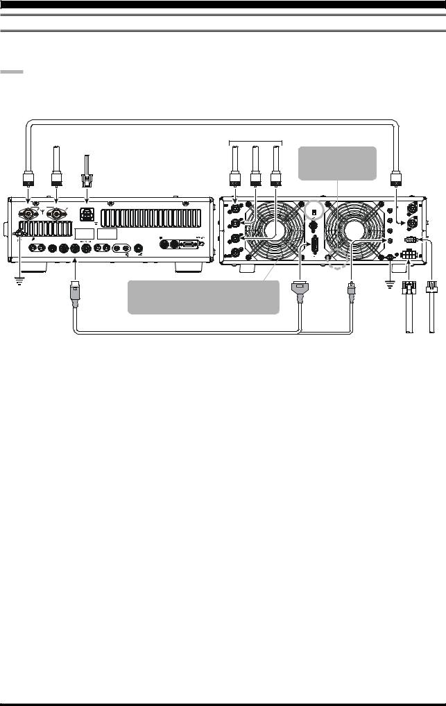
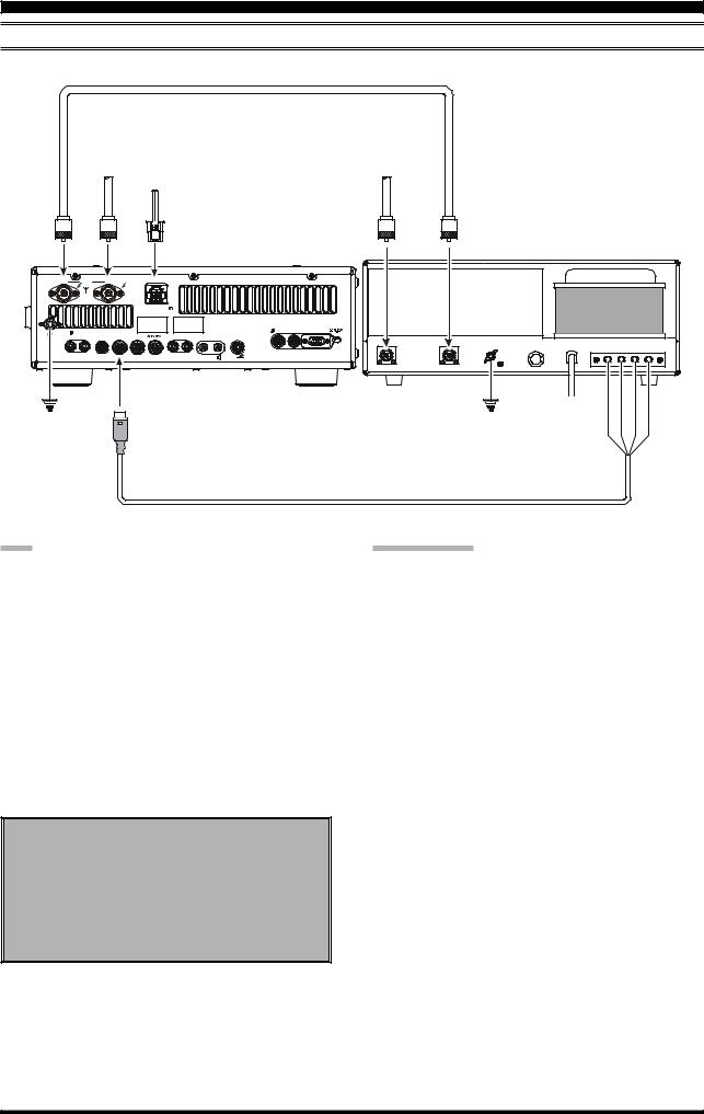
VL-1000 LINEAR AMPLIFIER INTERCONNECTIONS
Be sure that both the FT-950 and VL-1000 are turned off, then follow the installation recommendations contained in the illustration.
NOTE:
Please refer to the VL-1000 Operating Manual for details regarding amplifier operation. Please do not attempt to connect or disconnect coaxial cables when your hands are wet.
|
|
|
|
Antenna Cable (Not Supplied) |
|
|
|
50MHz Antenna |
HF Antenna |
|
|||
|
|
|
|
|||
|
|
|
DC 13.8 V |
|
|
|
|
ANT1 |
ANT2 |
INPUT |
ANT1 |
ANT2 |
ANT3 |
|
ANT |
|
DC IN |
ANT 1 |
|
|
1 |
2 |
|
|
|
||
ANT 2
INPUT: DC 13.8 V 22 A
ANT 3
|
-TUNE |
|
|
EXT |
-TUNE DMU |
CAT |
GND |
TO FROM |
ROT LINEAR TUNER |
PTT REC |
REM SPKR |
KEY |
|
|
|
|
|
|
|
ANT 4
Set the front panel’s
INPUT switch to the
“INPUT2”.
REMOTE
ON
OFF
BAND DATA 1
BAND DATA 2
GND |
LINEAR |
BAND2DATA- |
2ALC |
To link the FT-950 and VL-1000 Power switches, set the VL-1000 REMOTE switch to the “ON” position.
CT-118 Connection Cable (Option)
|
INPUT2 |
|
|
INPUT 1 |
|
|
PTT 1 |
|
|
PTT 2 |
|
|
INPUT 2 |
|
|
ALC 1 |
|
|
CONTROL |
|
|
ALC 2 |
|
|
DC48V IN |
|
|
GND |
|
GND |
DC48VIN |
CONTROL |
|
VP-1000 |
VP-1000 |
¾ ¾
FT-950 OPERATING MANUAL |
Page 13 |
INSTALLATION AND INTERCONNECTIONS
INTERFACING TO OTHER LINEAR AMPLIFIERS
50MHzAntenna |
|
Antenna Cable (Not Supplied) |
DC13.8V |
HFAntenna |
ANT1 |
ANT2 |
INPUT |
ANT |
INPUT |
|
1 |
ANT |
2 |
DC IN |
|
|
|
|
|
|
|
|
|
|
|
|
INPUT: DC 13.8 V |
|
|
|
|
|
|
|
|
|
|
|
|
22 A |
|
|
|
|
|
|
|
|
|
|
-TUNE |
|
|
EXT |
-TUNE DMU |
CAT |
|
|
|
|
|
GND |
TO |
FROM |
ROT LINEAR |
TUNER |
PTT REC REM SPKR |
KEY |
RF OUT |
RF IN |
|
|
|
|
|
|
|
|
|
|
|
GND |
FUSE |
AC |
E ALC E RY |
||
|
|
|
|
|
|
|
|
|
||||
|
|
|
|
|
|
|
|
|
|
|
|
GND |
LINEAR |
GND |
LightBlueBlack Green Yellow |
|
|
Linear Amplifier Connection Cable (T9207451: Option) |
|
NOTE
The TX GND OUT pin (pin 2) of the LINEAR jack is a transistor “open collector” circuit. It is capable of handling positive relay coil voltages up to +60VDC at 200 mA or +30 VDC at 1 A. If you plan to use multiple linear amplifiers for different bands, you must provide external band switching of the “Linear Tx” relay control line from the “TX GND OUT” line at the LINEAR jack.
The specified range for ALC voltage to be used with the FT-950 is 0 to -4 Volts DC.
Amplifier systems utilizing different ALC voltages will not work correctly with the FT-950, and their ALC lines must not be connected if this is the case.
Note
When the FC-40 is connected to the FT-950, TX GND (pin 2) of the TUNER jack and the LINEAR jack (pin 2) are common circuits.
Therefore, the maximum voltage at TX GND (pin 2) of the LINEAR jack must not exceed +5V.
IMPORTANT NOTE!
Do not exceed the maximum voltage or current ratings for the “TX GND OUT” pin (pin 2) of the LINEAR jack. This line is not compatible with negative DC voltages, or AC voltages of any magnitude.
Most amplifier control relay systems require only low DC voltage/current switching capability (typically, +12V DC at 25 ~ 75 mA), and the switching transistor in the FT-950 will easily accommodate such amplifiers.
Linear Amplifier Connection Cable (T9207451)
Color Code Information
Wire Color |
LINEA Jack (Pin Number) |
Function |
Orange |
1 |
+13.8 V |
Yellow |
2 |
TX GND |
Green |
3 |
GND |
Red |
4 |
BAND DATA A |
White |
5 |
BAND DATA B |
Blue |
6 |
BAND DATA C |
Violet |
7 |
BAND DATA D |
Brown |
8 |
TX INH |
Black |
9 |
EXT ALC IN |
Gray |
10 |
TX REQ IN |
Light Blue |
Case |
Shield |
Page 14 |
FT-950 OPERATING MANUAL |

PLUG /CONNECTOR PINOUT DIAGRAMS
|
MIC |
CAT |
|
DC IN |
||
|
|
UP |
|
N/A |
|
|
|
|
|
SERIAL OUT |
|
|
|
|
|
+5V |
|
|
|
|
|
|
|
SERIAL IN |
|
|
|
|
|
DOWN |
|
|
|
|
|
|
|
N/A |
|
|
|
|
|
FAST |
|
|
|
|
|
|
|
GND |
|
|
|
|
|
GND |
|
|
|
|
|
|
|
N/A |
|
|
|
|
|
PTT |
|
|
|
|
|
|
|
RTS |
|
|
|
|
|
MIC GND |
|
|
|
|
|
|
|
CTS |
|
|
|
|
|
MIC |
|
|
|
|
|
|
|
NC |
|
|
|
|
|
|
|
|
|
|
(as |
viewed from front panel) |
(as viewed from rear panel) |
(as |
viewed from rear panel) |
||
|
LINEAR |
TUNER |
RTTY/PKT |
|||
|
|
+13V OUT |
|
|
|
|
|
|
TX GND |
|
+13V OUT |
|
DATA IN |
|
|
GND |
|
TX GND |
|
|
|
|
BAND DATA A |
|
GND |
|
GND |
|
|
BAND DATA B |
|
RX D |
|
DATA PTT |
|
|
BAND DATA C |
|
TX D |
|
FSK IN |
|
|
BAND DATA D |
|
TUNER SENSE |
|
DATA OUT |
|
|
TX INH |
|
RESET OUT |
|
SQL OUT |
|
|
EXT ALC IN |
|
TX INH |
|
|
|
|
TX REQ IN |
|
|
|
|
(as |
viewed from rear panel) |
(as viewed from rear panel) |
(as |
viewed from rear panel) |
||
ROT ROTATOR |
PHONE |
RCA PLUG |
||||
|
( |
) |
|
|
|
|
|
|
CW ROTATION |
SIGNAL (RIGHT) |
|
GND or (---) |
|
|
|
CCW ROTATION |
|
|
|
|
|
|
SPEED |
|
|
|
|
|
|
DIRECTION |
|
|
|
|
|
|
GND |
|
|
|
|
|
|
NC |
SIGNAL (LEFT) |
GND |
SIGNAL or (+) |
|
|
|
|
||||
(as |
viewed from rear panel) |
|
KEY |
|
||
REM REMOTE |
|
|
||||
|
( |
) |
|
|
|
|
|
|
|
For Internal Keyer |
For Straight Key |
||
|
GND |
|
|
|
|
|
|
|
|
DOT DASH |
COMMON |
KEY |
GND |
SIGNAL |
|
|
|
Do not use |
||
|
|
|
|
|
||
|
|
|
|
|
2-conductor type plug |
|
|
EXT SPKR |
IMPORTANT NOTE: |
|
|
||
|
|
|
The μ-TUNE and DMU connectors are special connectors for this trans- |
|||
|
|
|
ceiver. Please do not connect any accessory or other device not specifically |
|||
|
GND |
|
approved by Vertex Standard. Failure to observe this precaution may cause |
|||
|
|
damage not covered by the Limited Warranty on this apparatus. |
||||
|
|
|
||||
SIGNAL |
|
|
|
|
|
|
FT-950 OPERATING MANUAL |
Page 15 |
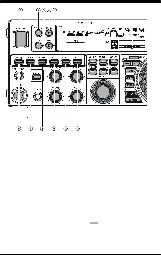
FRONT PANEL CONTROLS & SWITCHES
 [POWER] Switch
Press and hold in this switch for two seconds to turn the transceiver on. Similarly, press and hold in this switch for two seconds to turn the transceiver off.
 [ANT 1-2] Switch
Pressing this switch selects the ANT 1 or the ANT 2 connector on the rear panel, and allows convenient antenna switching at the press of button. The selected antenna jack is indicated on the Block Diagram Display shown in the Transceiver Display.
 [TUNE] Switch
This is the on/off switch for the FT-950’s Automatic Antenna Tuner.
Pressing this button momentarily places the antenna tuner in line between the transmitter final amplifier and the antenna jack (The “  ” icon will appear in the display). Reception is not affected.
Pressing and holding in this button for two seconds, while receiving in an amateur band, activates the transmitter for a few seconds while the automatic antenna tuner rematches the antenna system impedance for minimum SWR. The resulting setting is automatically stored in one of the antenna tuner’s 100 memories, for instant automatic recall later when the receiver is tuned near the same frequency.
Pressing this button momentarily, while the Tuner is engaged, will take the Automatic Antenna tuner out of the transmit line.
NOTE:
When the Automatic Antenna Tuner is tuning itself, a signal is being transmitted. Therefore, be certain that an antenna or dummy load is connected to the selected antenna jack before pressing and holding in the [TUNE] button to start antenna tuning.
Page 16 |
FT-950 OPERATING MANUAL |

FRONT PANEL CONTROLS & SWITCHES
 [MOX] Switch
Pressing this button engages the PTT (Push to Talk) circuit, to activate the transmitter (the LED inside this button will glow red). It must be turned off (the red LED will be off) for reception. This button replicates the action of the Push to Talk (PTT) switch on the microphone. When engaging the [MOX] button, or otherwise causing a transmission to be started, be certain you have either an antenna or 50-Ohm dummy load connected to the selected Antenna jack.
 [VOX] Switch
This button enables automatic voice-actuated transmitter switching in the SSB, AM, and FM modes. While activated, the LED inside this button glows red. The controls affecting VOX operation are the Menu items “114 TGEN V GAIN”, “115 TGEN VOX DLY”, and “116 TGEN ANTI VOX”. By proper adjustment of these controls, hands-free voice-actuated operation is possible.
 [MONI] (Monitor) Switch
This button enables the transmit monitor in SSB, CW, AM, and FM modes. While activated, the “ ” icon appears in the display. The Monitor audio level may be adjusted by turning the [MONI] knob.
ADVICE:
When using headphones, the Monitor function is very helpful while adjusting the Parametric Equalizer or other voice quality adjustments. The voice heard in the headphones represents the transmitted audio qualities.
 [PROC] (Processor) Switch
This button enables the Parametric Microphone Equalizer and Speech Processor for SSB/AM transmission. When the Parametric Microphone Equalizer is activated, the “  ” icon appears in the display. When the Speech Processor is activated, the “
  ” and “
  ” icons appear in the display. Adjustment of the Processor level is accomplished via the Menu item “109 TGEN PROCLVL”.
ADVICE:
The Speech Processor is a tool for increasing the average power output through a compression technique. However, if the Processor level is advanced too far, the increase in compression becomes counter-productive, as intelligibility will suffer. We recommend that you monitor the sound of your signal using the Monitor (with headphones).
When the optional Data Management Unit (DMU2000) is connected, you may use the Audio Scope/ Oscilloscope page to help you adjust the setting of the compression level of the Speech Processor for optimum performance using your voice and microphone.
 [SPOT] Switch
This button turns on the CW receiver spotting tone; by matching the SPOT tone to that of the incoming CW signal (precisely the same pitch), you will be “zero beating” your transmitted signal on to the frequency of the other station.
The offset tone frequency will be indicated in the frequency display area of the display while this button is pressed.
 [BK-IN] Switch
This button turns the CW break-in capability on and off. While CW break-in is activated, the “  ” icon appears in the display.
 [KEYER] Switch
This button toggles the internal CW keyer on and off. While activated, the “ ” icon appears in the display. The Keyer sending speed is adjusted via the front panel’s [SPEED] knob and the CW Hang Time is adjusted via the Menu item “044 A1A DELAY”.
 [AGC] Switch
This button selects the AGC characteristics for the receiver. Available selections are FAST, MID, SLOW, or AUTO. The “AGC” icon will change according to the AGC characteristics selected.
Press the [AGC] button repeatedly to select the desired receiver-recovery time constant. Press and hold in the [AGC] button for two seconds to disable the AGC (for testing or weak-signal reception).
ADVICE:
The Attenuator may be used in conjunction with the [IPO] button to provide two stages of signal reduction when an extremely strong signal is being received.
If the AGC receiver-recovery time is set to “Off” by pressing and holding in the [AGC] button, the S-meter will no longer deflect. Additionally, you will likely encounter distortion on stronger signals, as the IF amplifiers and the following stages are probably being overloaded.
FT-950 OPERATING MANUAL |
Page 17 |

FRONT PANEL CONTROLS & SWITCHES
 PHONES Jack
A 1/4-inch, 3-contact jack accepts either monaural or stereo headphones with 2- or 3-contact plugs. When a plug is inserted, the loudspeaker is disabled.
NOTE:
When wearing headphones, we recommend that you turn the AF Gain levels down to their lowest settings before turning power on, to minimize the impact on your hearing caused by audio “pops” during switchon.
 [METER] Switch
This button determines the function of the meter during transmission.
Press this button to change the meter function in the transmit mode as follows:
ALC Æ SWR Æ ID Æ VDD Æ COMP Æ ALC ……
ALC: Indicates the relative ALC voltage.
SWR: Indicates the Standing Wave Ratio (Forward/ Reflected).
ID: Indicates the final amplifier drain current. VDD: Indicates the final amplifier drain voltage. COMP: Indicates the speech compressor level (SSB/
AM modes only).
 [MIC GAIN] Knob
This knob adjusts the microphone input level for (nonprocessed) SSB and AM transmission.
The frequency display will show the relative microphone gain level for 3 seconds whenever this knob is turned.
ADVICE:
Adjust the [MIC GAIN] knob while speaking in a somewhat louder than normal voice level, watch the ALC level and adjust the [MIC GAIN] knob so that the ALC level indication just reaches the right edge of the ALC scale. Then, when you speak in your normal voice level, you will not be over-driving the microphone amplifier stages.
 [SPEED] Knob
This knob adjusts the keying speed of the internal CW keyer (4 ~ 60 WPM). Clockwise rotation increases the sending speed.
The frequency display will show the keying speed for 3 seconds whenever this knob is turned.
 Microphone Connector
This 8-pin jack accepts input from a microphone utilizing a traditional YAESU HF transceiver pinout.
Page 18 |
FT-950 OPERATING MANUAL |
FRONT PANEL CONTROLS & SWITCHES
 KEY Jack
This 1/4-inch, 3-contact jack accepts a CW key or keyer paddles (for the built-in electronic keyer), or output from an external electronic keyer. Pinout is shown on page 15. Key up voltage is +3.3 V DC, and key down current is 0.3 mA. This jack may be configured for keyer, “Bug”, “straight key”, or computer keying interface operation via Menu item “037 A1A F-TYPE” (see page 111). There is another jack with the same name on the rear panel, and it may be configured independently for Internal Keyer or pseudo-straight-key operation.
NOTE:
You cannot use a 2-contact plug in this jack (to do so produces a constant “key down” condition).
 [MONI] Knob
This knob adjusts the audio level of the transmit monitor during transmission, when activated by the [MONI] button.
 [SQL] Knob
This knob sets the signal level threshold, below which the receiver audio is muted, in all modes. It is very useful during local rag-chews, to eliminate noise between incoming transmissions. This control is normally kept fully counter-clockwise (off), except when scanning and during FM operation.
 [SHIFT] Switch
Pressing this button allows you to move the IF DSP Bandwidth higher or lower, using the [SELECT] knob. While activated, the LED inside this button glows orange.
 [NOTCH] Switch
Pressing this button allows you to adjust the center frequency of the IF Notch filter using the [SELECT] knob. While activated, the LED inside this button glows orange. Press the [SELECT] knob briefly to toggle the IF Notch filter on/off.
 [WIDTH] Switch
Pressing this button allows you to adjust the overall bandwidth of the IF DSPfilter using the[SELECT] knob.While activated, the LED inside this button glows orange.
 [μ-TUNE] Switch
Pressing this button allows you to adjust the center frequency of the μ-Tuning filter passband using the [SELECT] knob, when the optional RF μTuning Kit is connected. While activated, the LED inside this button glows orange. Press the [SELECT] knob briefly to toggle the μ-Tuning function on/off.
 [CONT] Switch
Pressing this button allows you to select the DSP Contour filter response using the [SELECT] knob. While activated, the LED inside this button glows orange. Press the [SELECT] knob briefly to toggle the IF Contour filter on/off.
Furthermore, in the CW mode, press and hold this button for 2 seconds to activate the APF (Audio Peak Filter) which provides a very narrow audio bandwidth.
The APF circuit is an automatic circuit, and there is no adjustment knob for the APF.
 [CLEAR] Switch
Pressing this button will reset to factory default the functions, which are selected with the five buttons at the left of this button.
 [SELECT] Knob
This knob is used to adjust the status of the functions selected by the five buttons located above the knob.
EFFECT
Rotate the [SELECT] knob to move the passband of the IF DSP filter by 20 Hz steps. The total adjustment range is ±1 kHz. The position of the passband can be observed on the display. Furthermore, the frequency display will show the shift value of the IF SHIFT for 3 seconds whenever the [SELECT] knob is turned.
Rotate the [SELECT] knob to set the overall bandwidth of the IF DSP filter. Counter-clock- wise rotation reduces the bandwidth, while clockwise rotation increases the bandwidth. The current bandwidth can be observed on the display. Furthermore, the frequency display will show the bandwidth of the IF passband for 3 seconds whenever the [SELECT] knob is turned.
Press the [SELECT] knob to turn the CONTOUR filter on and off. Rotate the [SELECT] knob to adjust the CONTOUR filter response.
The peak position of the CONTOUR filter can be observed on the display. Furthermore, the frequency display will show the CONTOUR frequency for 3 seconds whenever the [SELECT] knob is turned.
Press the [SELECT] knob to turn the IF NOTCH filter on and off. Rotate the [SELECT] knob to adjust the center frequency of the IF NOTCH filter. The null position of the IF NOTCH filter can be observed on the display. Furthermore, the frequency display will show the center frequency of the IF NOTCH filter for 3 seconds whenever the [SELECT] knob is turned.
] Press the [SELECT] knob to turn the optional RF μTuning Kit on and off. Rotate the [SELECT] knob to adjust the center frequency of the μ-Tuning filter. The peak position of the μ- Tuning filter can be observed on the Tuning Offset Indicator field of the display.
If the [SELECT] knob is turned too slowly, the frequency display may not show the value. This is to prevent undesired display of the functions caused by noise or slight vibration of the controls; however, the actual value will be changed even if not displayed.
You can observe the fine adjustment for a few seconds while the display is active.
While adjusting functions, the display may occasionally skip one of the numbers in the sequence; this is due to “rounding” of the encoder steps in the ADC converter. Set the values to your preference, they are unique to your radio and may not directly correspond to other units.
The [SELECT] knob is also used to select the Menu item when the Menu mode is engaged.
Press and hold the [SELECT] knob for one second to activate the optional Voice Memory feature for the SSB/ AM/FM modes, or the Contest Keyer for the CW mode. See page 64 (Voice Memory feature) or page 78 (Contest Keyer) for details.
FT-950 OPERATING MANUAL |
Page 19 |

FRONT PANEL CONTROLS & SWITCHES
 [(VFO-A)RX] Indicator/Switch
Press this button to activate receive on the VFO-A frequency. The LED inside the button will glow green when the transceiver receives the VFO-A frequency. When the transceiver receives the VFO-A frequency, pressing this button momentarily will mute the receiver, and the indicator will blink. Pressing the button once more will restore receiver operation, and the indicator will glow green steadily.
 QMB (Quick Memory Bank) Switches
[STO] (Store) Button
Pressing the [STO] button copies the contents (frequency, mode, bandwidth, and also FM repeater frequency shift/direction and CTCSS functions) of VFO- A, into consecutive QMB Memories.
[RCL] (Recall) Button
Pressing the [RCL] button, recalls one of up to five Quick Memory Bank memories for operation.
 [NAR] (Narrow) Switch
In the SSB/CW/RTTY/PSK modes, this button is used to set the DSP (digital) IF filters to Narrow bandwidth.
ADVICE:
You may adjust the bandwidth using the [SELECT] knob when the [WIDTH] button is engaged.
In the AM mode, this button is used to toggle the receiver’s bandwidth between wide (9 kHz) and narrow (6 kHz).
In the FM mode on the 28 MHz and 50 MHz bands, this button is used to toggle the FM deviation/bandwidth between wide (±5.0 kHz Dev./25.0 kHz BW) and narrow (±2.5 kHz Dev./12.5 kHz BW).
 [SPLIT] Switch
Press this button to operate split frequency between VFO-A(used for reception) and VFO-B (used for transmission). If you press and hold in the [SPLIT] button for one second, the “Quick Split” feature will be engaged. VFO-B will automatically be set to a frequency 5 kHz higher than the VFO-A frequency, with the same operating mode. The transceiver will be placed in the Split mode.
Page 20 |
FT-950 OPERATING MANUAL |

FRONT PANEL CONTROLS & SWITCHES
 [TXW] (TX Watch) Switch
Pressing this button lets you monitor the transmit frequency when split frequency operation is engaged. Release the button to return to normal split frequency operation.
 [C.S] Switch
Press this button momentarily to directly recall a favorite Menu Selection.
To program a Menu selection to the [C.S] button: press the [MENU] button to enter the Menu. Select the Menu item you want to set as the short cut. Then press and hold in the [C.S] button for one second; this will lock in the selected Menu item as the short cut.
 [MENU] Switch
This button is used to access the Menu system. The various transceiver characteristics may be configured. Menu operation is described in detail, in this manual, beginning on page 104.
IMPORTANT NOTE:
Pressing this button momentarily, activates the Menu. The Menu items will appear on the display; once you have changed the parameters, you must press and hold in the [MENU] button for one second to save any configuration changes (momentarily pressing the [MENU] button to exit will not save the changes).
 Main Tuning Dial Knob
This large knob adjusts the operating frequency of the VFO-A or a recalled memory. Clockwise rotation of this knob increases the frequency. Default tuning increments are 10 Hz (100 Hz in AM and FM modes); when the [FAST] button is pressed, the tuning steps increase. The available steps are:
OPERATING MODE |
1 STEP |
1 DIAL ROTATION |
LSB/USB/CW/RTTY/PKT(LSB) |
10 Hz (100 Hz) |
10 kHz (100 kHz) |
AM/FM/PKT(FM) |
100 Hz (1 kHz) |
100 kHz (1 MHz) |
Numbers in parentheses indicate steps when the [FAST] button is On.
ADVICE:
The tuning steps for the Main Tuning Dial knob are set, at the factory, to 10 Hz per step. Via Menu item “084 TUN DIALSTP”, however, you may change this setting from 10 Hz to 1 or 5 Hz instead.
 [(VFO-A)TX] Indicator/Switch
When this button is pushed, the LED inside the button will glow red; and, when the PTT switch is pressed, the transceiver will transmit on the VFO-A frequency (subject to any Clarifier offset, of course).
ADVICE:
If this indicator is not illuminated, it means the [(VFO- B)TX] Indicator/Switch has been selected (it will be glowing red). In this case, transmission will be on the frequency and mode programmed for VFO-B.
 [FAST] Switch
Pressing this button will change the tuning rate of the Main Tuning Dial knob (VFO-A) or the VFO-B Tuning Knob ([CLAR/VFO-B] knob) to 100 Hz/step.
When this function is activated, the “ ” icon appears in the display.
ADVICE:
This switch affects VFO-A and VFO-B independently.
 [LOCK] Switch
This button toggles locking on/off for the Main Tuning Dial knob (VFO-A) or the VFO-B Tuning Knob ([CLAR/VFO-B] knob). With “Lcok” on, the Main Tuning Dial knob or [CLAR/VFO-B] knob can still be turned, but the frequency will not change, and the “ ” icon appears in the display.
ADVICE:
This switch locks VFO-A and VFO-B independently.
 [AXB] Switch
Press this button momentarily to transfer the frequency or memory channel data, from VFO-A to VFO-B, overwriting any previous contents in VFO-B. Use this key to set both VFO-A and VFO-B to the same frequency and mode.
 [AXWB] Switch
Pressing this button momentarily, exchanges the frequency or memory channel data, of VFO-A and VFO-B.
 [V/M] Switch
This button toggles frequency control between VFO- A and the memory system. In memory mode, either “ ” or “
 ” icon will be shown under the frequency Display field to indicate the current selection. If you have tuned the frequency off the Memory channel, the “
 ” icon will be displayed. Pressing the [V/M] button returns the display to the original memory frequency, and the “
 ” icon will again be displayed. Pressing it once more returns frequency operation to the VFO-A, and the icon will no longer be displayed.
 [MXA] Switch
Pressing this button momentarily, will display the contents of the currently-selected memory channel for 10 seconds.
Holding [MXA] button in for one second copies the data from the selected memory to VFO-A, and two beeps sound. Previous data in VFO-A will be overwritten.
 [AXM] Switch
Pressing this button momentarily, displays the contents of the currently-selected memory channel for 10 seconds. Pressing and holding in this key for one second (until the double beep) copies the current operating data into the currently selected memory channel, overwriting any previous data stored there.
FT-950 OPERATING MANUAL |
Page 21 |

FRONT PANEL CONTROLS & SWITCHES |
 [BAND] Keys
These keys allow one-touch selection of the desired Amateur band (1.8 ~ 50 MHz).
The keys may also be used for direct entry of a desired operating frequency during VFO operation.
 [MODE] Switches
Pressing one of these switches, selects the operating mode, as shown in the chart below. Repeated presses of a particular switch will toggle to the alternate mode, or step through the available selections. For example pressing [SSB] button repeatedly toggles between “LSB” and “USB” mode.
For [RTTY/PKT] operation, press the button briefly to toggle between “RTTY” and “PKT”. Press and hold the button, repeatedly, to step through
“PKT(LSB)” J “PKT(USB)” J “PKT(FM)” J “PKT(LSB)” ....
SWITCH |
VARIABLE MODE SELECTIONS |
[SSB] |
LSB Q USB |
[CW] |
CW(LSB) Q CW(USB) |
[AM/FM] |
AM Q FM |
[RTTY/PKT] |
Momentarily: RTTY(LSB) Q PKT(LSB) |
|
Press & Hold: RTTY(LSB) Q RTTY(USB) or |
|
PKT(LSB) J PKT(USB) J |
|
PKT(FM) J PKT(LSB) .... |
 [ATT] Switch
This button selects the degree of attenuation, if any, to be applied to the receiver input.
Available selections are –6 dB, –12 dB, –18 dB, or OFF. The attenuation level appears in the ATT column of the Block Diagram Display on the display.
ADVICE:
The Attenuator may be used in conjunction with the [IPO] button to provide two stages of signal reduction when an extremely strong signal is being received.
 [IPO] (INTERCEPT POINT OPTIMIZATION) Switch
This button may be used to set the optimum front end characteristics of the receiver circuit for a very strong signal environment. Available selections are AMP 1 (low distortion amplifier), AMP 2 (2-stage low-distor- tion RF amplifier), or ON (bypasses the front end RF amplifier), and the selected receiver RF amplifier appears in the IPO column of the Block Diagram Display on the display.
Page 22 |
FT-950 OPERATING MANUAL |

FRONT PANEL CONTROLS & SWITCHES
 [R.FLT] (ROOFING FILTER) Switch
This button selects the bandwidth of the receiver first IF Roofing Filter. Available selections are 3 kHz, 6 kHz, 15 kHz, or Auto. The selected bandwidth appears in the FLT column of the Block Diagram Display on the display.
ADVICE:
Because the roofing filter is in the first IF, the protection it provides against interference is quite significant. When set to AUTO, SSB bandwidth is 6 kHz, CW is 3 kHz, FM and RTTY are 15 kHz. On a crowded SSB band, however, you may wish to select the 3 kHz filter, for the maximum possible interference rejection.
 [NB] Switch
This button turns the IF Noise Blanker on and off. Press this button momentarily to reduce short-duration pulse noise; the “  ” icon will appear in the display.
Press and hold this button in for one second to reduce longer-duration man-made pulse noises; the “  ” icon will blink for three seconds, then will appear continuously in the display.
Press this button again to disable the noise blanker; the “  ” icon will disappear.
 [AF GAIN] [RF GAIN] Knobs
[AF GAIN] Knob
The inner [AF GAIN] knob sets the receiver’s audio volume level. Typically, you will operate with this control set between the 9 o’clock and 10 o’clock positions.
[RF GAIN] Knob
The outer [RF GAIN] knob is the receiver’s RF gain control, which adjusts the gain of the receiver’s RF and IF amplifier stages. This control is normally left in the fully clockwise position.
 [RX CLAR] Switch
Pressing this button activates the RX Clarifier. This will allow you to temporarily adjust the receiving frequency up to ±9.99 kHz with the [CLAR/VFO-B] knob. Press this button once more to return the receiver to the original frequency; the Clarifier offset will be remembered, in case you want to use it again. To cancel the Clarifier offset, press the [CLEAR] button.
 [TX CLAR] Switch
Pressing this button activates the TX Clarifier, to allow offsetting the transmit frequency temporarily. Press this button once more to return the transmitter to the original frequency; the Clarifier offset will be remembered, though, in case you want to use it again. To cancel the Clarifier offset, press the [CLEAR] button.
 [CLEAR] Switch
Pressing this button clears out any frequency offset you have programmed into the Clarifier register (thereby setting the offset to “Zero”).
 [(VFO-B)RX] Indicator/Switch
This button switches the receiving frequency to VFO- B, the green LED imbedded within the button will light up. Pressing this button again will return the receiving frequency to VFO-A, and the imbedded green LED will turn off.
 [(VFO-B)TX] Indicator/Switch
This button transfers control of the transmit frequency/ mode to VFO-B, and the red LED in the button will light up. Pressing this button again will transfer frequency/mode control back to the VFO-A side, and the red LED imbedded within this button will turn off.
 [BAND] Switch
Pressing this button allows you to select the operating band (Amateur bands) by turning the [CLAR/VFO- B] knob.
 [GRP] Switch
Pressing this button allows you to select the memory group by turning the [CLAR/VFO-B] knob.
 [MHz] Switch
Pressing this button allows you to tune the VFO frequency down or up in 1 MHz increments, using the [CLAR/VFO-B] knob.
 [CLAR/VFO-B] Knob
This knob usually tunes the Clarifier offset frequency up to ±9.99 kHz. Additionally, it is used to adjust the functions selected with five buttons located around the knob.
FUNCTION |
EFFECT |
SWITCH |
|
[(VFO-B)RX] |
Rotate the [CLAR/VFO-B] knob to adjust |
|
the VFO-B frequency, in the same step as |
|
the Main Tuning Dial knob. The Frequency |
|
Display will be changed to show the VFO- |
|
B frequency. |
[BAND] |
Rotate the [CLAR/VFO-B] knob to change |
|
the amateur band selection. |
[GRP] |
Rotate the [CLAR/VFO-B] knob to select |
|
the memory group. |
[MHz] |
Rotate the [CLAR/VFO-B] knob to tune the |
|
VFO frequency in 1 MHz step. |
[MCH] |
Rotate the [CLAR/VFO-B] knob to select |
|
the memory channel. |
 [MCH] Switch
Pressing this button allows you to select the memory channel using the [CLAR/VFO-B] knob.
FT-950 OPERATING MANUAL |
Page 23 |
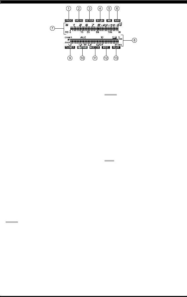
DISPLAY INDICATIONS (LEFT SIDE)
 PROC
PROC
This indicator appears whenever the DSP Speech Processor is activated.
 MONI
MONI
This indicator appears whenever the transmit monitor circuit is activated.
 KEYER
KEYER
This indicator appears whenever the internal CW keyer is activated.
 BK-IN
BK-IN
This indicator appears whenever CW break-in operation is activated.
 NB
NB
This indicator appears when the receiver’s “short-du- ration” Noise Blanker is activated.
This indicator will blink for three seconds, and thereafter appears continuously, when the receiver’s “longer pulse” Noise Blanker is activated.
 NAR
NAR
This indicator appears whenever the receiver’s narrow IF DSP filter is engaged.
 S/PO
S/PO
On receive, this indicates the received signal strength, from S-0 to S-9+60dB on receiving.
On transmit, it indicates the RF Power Output, from 0 to 150 Watts on transmit.
ADVICE:
The S and PO meters can be set to the Peak-hold function via the Menu items “007 DISP PKH S” and “008 DISP PKH PO”.
 Multi Function Meter
The five Transmit Multi-Meter functions are listed below.
ALC |
Indicates the relative ALC voltage. |
SWR |
Indicates the Standing Wave Ratio |
|
(Forward: Reflected), from 1.0 to 3.0. |
ID |
Indicates the final amplifier drain current, |
|
0 to 30 ampere. |
VDD |
Indicates the final amplifier drain voltage |
|
(nominal value: 13.8 V). |
COMP |
Indicates the speech compressor level, |
|
from 0 to 30 dB. |
The function displayed is selected by repeatedly pressing the [METER] switch, to step through the available
meter displays. (ALC Æ SWR Æ ID Æ VDD Æ COMP Æ ALC ....)
ADVICE:
The ALC and ID meters can be set to the Peak-hold function via the Menu items “009 DISP PKH ALC” and “010 DISP PKH ID”.
 TUNER
TUNER
This indicator appears when the internal Automatic Antenna Tuner is activated.
 HI-SWR
This indicator appears if the directional coupler and microprocessor detect an abnormally high SWR condition (over 3.0:1) that cannot be resolved by the Automatic Antenna Tuner.
NOTE:
If this indicator appears, check to be sure that you have the correct antenna selected for the current operating band. Also check the condition of the antenna, the coaxial cable, and/or the connectors on the cable, to locate and correct the fault.
 MIC EQ
This indicator appears whenever the Three-Band Parametric Microphone Equalizer is activated via the Menu.
 REC
REC
This indicator appears while the optional Voice Memory Unit is recording your voice message, or the Contest Keyer is recording your CW keying.
 PLAY
PLAY
This indicator appears while the optional Voice Memory Unit is playing back the recorded voice message, or the recorded Contest CW keying.
Page 24 |
FT-950 OPERATING MANUAL |

DISPLAY INDICATIONS (CENTER)
 Block Diagram Display
ANT (1, 2):
Indicates the antenna selected by the front panel [ANT 1-2] button.
ATT (OFF, –6 dB, –12 dB, –18 dB):
Indicates the attenuation level, selected by the front panel [ATT] button.
FLT (μ-TUNE, THRU):
Indicates when the optional μ-TUNE RF filter is selected by the front panel [μ-TUNE] button.
ADVICE:
The icon will not appear unless the optional μ-TUNE unit is connected.
IPO (AMP 1, AMP 2, ON):
Indicates which front end RF amplifier is selected by the front panel [IPO] button.
R.FLT (AUTO, 3 kHz, 6 kHz, 15 kHz):
Indicates the receiver IF Roofing Filter, which is selected by the front panel [R.FLT] button.
AGC (AUTO, FAST, MID, SLOW):
Indicates the AGC decay time setting, selected by the front panel [AGC] switch.
 DNR
DNR
This indicator appears whenever the Digital Noise Reduction feature is activated.
 DNF
DNF
This indicator appears whenever the Digital Notch Filter is activated.
 CONTOUR
The peak position of the CONTOUR Filter is graphically depicted here when the CONTOUR Filter is activated.
 NOTCH
NOTCH
The null position of the IF Notch Filter is graphically depicted here when the IF Notch Filter is activated.
 WIDTH
WIDTH
Indicates the bandwidth setting of the DSP IF filter.
 SHIFT
SHIFT
Graphically indicates the peak position of the DSP IF filter.
FT-950 OPERATING MANUAL |
Page 25 |
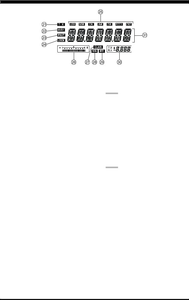
DISPLAY INDICATIONS (RIGHT SIDE)
 TX
TX
This indicator appears during transmission.
 BUSY
BUSY
This indicator appears whenever the receiver squelch is open. If this indicator is not showing, and reception seems to have been lost on the receiver for no apparent reason, check the position of the [SQL] knob and rotate it fully counter-clockwise to restore reception.
 FAST
FAST
This indicator appears when the Main Tuning Dial knob’s, tuning rate is set to “fast”.
 LOCK
LOCK
This indicator appears when the Main Tuning Dial knob is locked.
 LSB, USB, CW, AM, FM, RTTY, PKT
Displays the current operating mode.
 Tuning Offset Indicator
This is a tuning scale that, as configured from the factory, provides a visual CW tuning indication of the incoming signal’s offset from your transceiver’s CW carrier frequency, as programmed by the relative clarifier offset, or the peak position of the optional μ-TUNE filter.
 CLAR
CLAR
This indicator appears whenever the Clarifier function is activated.
 MR
MR
This indicator appears when the FT-950 is in the Memory Recall mode.
 MT
MT
This indicator appears when the FT-950 is in the Memory Tune mode to indicate that the memory contents have been temporarily changed.
 Multi-Display Window
This window displays either the Clarifier offset or the
Memory Channel Number.
ADVICE:
During FM operation, the Repeater Shift will be
indicated in this window.ANegative frequency shift will be indicated by “–” while a Positive frequency shift will be indicated by “+”.
When setting the Menu items, the current setting will appear in this area.
When setting the CTCSS Tone Squelch Encoding, the current repeater shift direction will appear in this area.
When controlling the optional rotator, the antenna direction will appear in this area during setup.
 Frequency Display
This is the frequency display.
ADVICE:
When adjusting the keying speed of the internal CW keyer, the keying speed will appear in this area during setup.
When adjusting the “null” position of the Notch filter, the center frequency of the Notch filter will appear in this area during setup.
When adjusting the “null” or “peak” position of the Contour filter, the center frequency of the Contour filter will appear in this area during setup.
When adjusting the microphone gain, the microphone gain level will appear in this area during setup.
When adjusting the passband of the IF DSP filter, the shift value of the IF SHIFT will appear in this area during setup.
When adjusting the bandwidth of the IF DSP filter, the bandwidth of the IF passband will appear in this area during setup.
When setting the Menu items, the Menu item number, Menu group name, and Menu item name will appear in this area during setup.
When setting the CTCSS frequency for Encoding or Tone Squelch operation, the current tone information will appear in this area during setup.
When controlling the optional rotator, the current rotation speed will appear in this area during setup.
Page 26 |
FT-950 OPERATING MANUAL |
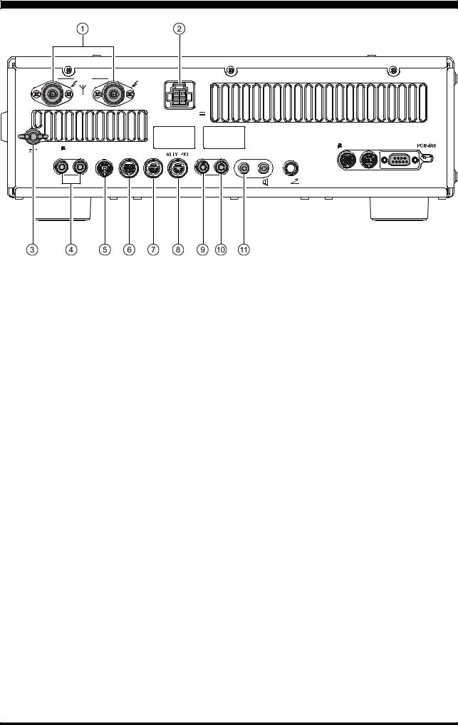
REAR PANEL
1 |
ANT |
2 |
DC IN |
|
|
|
|
|
INPUT: DC 13.8 V |
|
|
|
|
|
|
|
|
|
|
|
|
22 A |
|
|
|
|
|
|
|
|
-TUNE |
|
|
|
|
|
|
EXT |
-TUNE |
DMU |
CAT |
|
|
ROT |
LINEAR |
TUNER |
PTT |
REC |
REM |
KEY |
|
|
|||
GND |
TO |
FROM |
SPKR |
|
|
|||||||
|
|
|
|
|
|
|
|
|
|
|
|
|
 ANT 1/2 Jacks
Connect your main antenna(s) here, using a type-M (PL-259) connector and coaxial feed lines. The internal antenna tuner affects only the antenna(s) connected here, and only during transmission.
 DC IN Jack
This is the DC power supply connection for the transceiver. Use the supplied DC cable to connect directly to a DC power supply, which must be capable of supplying at least 22 A @13.8 VDC.
 GND
GND
Use this terminal to connect the transceiver to a good earth ground, for safety and optimum performance. Use a large diameter, short braided cable for making ground connections, and please refer to page 9 for other notes about proper grounding.
 TUNER Jack
This 8-pin output jack is used for connection to the FC-40 External Automatic Antenna Tuner. Pinout is shown on page 15.
 RTTY/PKT Jack
This 6-pin input/output jack accepts AFSK input from a Terminal Node Controller (TNC); it also provides fixed level (100-mV @600 Ohms) receiver audio output, and FSK keying line. Pinout is shown on page 15.
 PTT Jack
This RCA input jack may be used to provide manual transmitter activation using a footswitch or other switching device. Its function is identical to the [MOX] button on the front panel. The same line is available at the RTTY/PKT jack for TNC control. Open-circuit voltage is +5 VDC, and closed-circuit current is 1 mA.
 μ-TUNE Jacks
These jacks are used to connect the optional RF μTuning Kit, signal in and signal out.
 ROT (ROTATOR) Jack
This covered 6-pin MINI-DIN Jack accepts a cable to connect to a YAESU Antenna Rotator Control, G- 800DXA, 1000DXA, or 2800DXA (listed models are current as of early 2009). You may control the antenna azimuth, rotation, and rotation speed, using the [BAND] buttons on the front panel.
 LINEAR Jack
This 10-pin output jack provides band selection data, which may be used for control of optional accessories such as the VL-1000 Solid-state Linear Amplifier. Pinout is shown on page 15.
 REC Jack
This RCA jack provides low-level receiver audio output and transmit (monitor) audio output (requires the [MONI] button is turned on), for recording or external amplification. Peak signal level is 30 mVp-p at 10 kOhms.
 REM (REMOTE) Jack
By plugging in the optional FH-2 Remote Control Keypad to this gold-plated jack, direct access to the FT950 CPU is provided for control functions such as contest memory keying, plus frequency and function control.
FT-950 OPERATING MANUAL |
Page 27 |
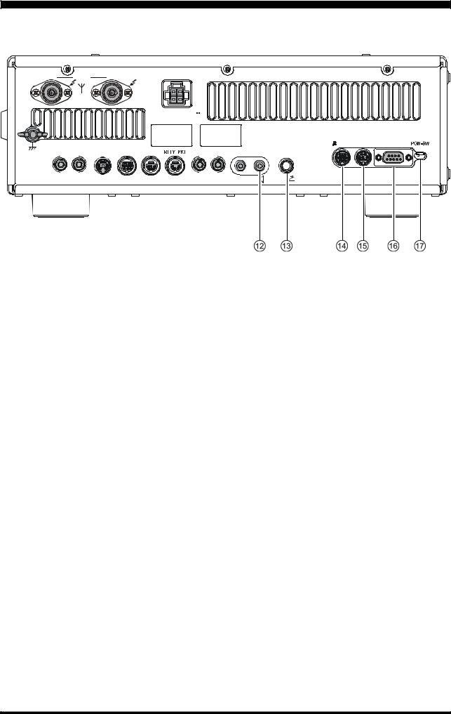
REAR PANEL
1 |
ANT |
2 |
DC IN |
INPUT: DC 13.8 V  22 A
22 A
 -TUNE
-TUNE
GND |
TO FROM ROT LINEAR TUNER |
PTT REC |
||||||||
|
|
|
|
|
|
|
|
|
|
|
|
EXT |
-TUNE |
DMU |
CAT |
REM |
KEY |
|
|
|
SPKR |
|
|
 EXT SPKR Jack
This 3.5-mm, 2-contact, gold-plated jack provides variable audio output for an external loudspeaker. The audio output impedance at this jack is 4 - 8 Ohms, and the level varies according to the setting of the front panel [AF GAIN] knob. Inserting a plug into this jack disables the internal loudspeaker.
 KEY Jack
This 1/4-inch 3-contact jack accepts a CW key or keyer paddle. A two-contact plug cannot be used in this jack. Key-up voltage is +3.3 V DC, and key-down current is 0.3 mA. Plug wiring is shown on page 15. This jack may be configured for keyer, “Bug”, “straight key”, or computer keying interface operation via Menu item “039 A1A R-TYPE”.
 μ-TUNE Jack
This covered 10-pin mini-DIN jack is used for control of the optional RF μTuning Kit.
 DMU Jack
This covered 8-pin mini-DIN jack accepts a cable to connect an optional DMU-2000 Data Management Unit.
 CAT Jack
This 9-pin serial DB-9 jack allows external computer control of the FT-950. Connect a serial cable here and to the RS-232C COM port on your personal computer (no external interface is required).
 PGM-SW Switch
This slide switch is used for updating the transceiver’s firmware. The update software and instructions are available for download from the Vertex Standard website (http://www.yaesu.com/).
Page 28 |
FT-950 OPERATING MANUAL |
 Loading...