


INSTRUCTIONS FOR USE
SINGLE SPLIT AIR CONDITIONER WITH GREEN GAS AND WITH GAS R22
PREPARATION BEFORE USE SAFETY PRECAUTIONS IDENTIFICATION OF PARTS REMOTE CONTROL OPERATION INSTRUCTIONS MAINTENANCE TROUBLESHOOTING PROTECTION
INSTALLATION INSTRUCTIONS
ELECTRICAL CONNECTION
CLASSIC RANGE R22
GREEN RANGE 
Disposal of old appliances
•This appliance is marked according to the European directive 2002/96/EC on Waste Electrical and Electronic Equipment (WEEE).
By ensuring this product is disposed of correctly, you will help prevent potential negative consequences for the environment and human health, which could otherwise be caused by inappropriate waste handling of this product.
The symbol |
on the product, or on the documents accompanying the product, indicates that this |
appliance may not be treated as household waste. Instead it shall be handed over to the applicable collection point for the recycling of electrical and electronic equipment.
Disposal must be carried out in accordance with local environmental regulations for waste disposal. For more detailed information about treatment, recovery and recycling of this product, please contact your local city office, your household waste disposal service or the shop where you purchased the product.
137
PREPARATION BEFORE USE
Before using the air conditioner, be sure to check and preset the following.
• Remote Control presetting
Each time the batteries are replaced in the remote control, the remote control is pre-set on Heat Pump. If the air conditioner that you purchased is Cooling only, then the pre-set on Heat Pump will not bring any changes.
• Back-light function (optional)
Pressing any button of the remote control for about 2 seconds, the back-light turns on. Once the button is released, it automatically turns off after 10 seconds.
Note: Back-light is an optional function.
• Auto Restart Presetting
The Auto restart function is not preset by the manufacturer. To set the auto restart function, press the Emergency button (ON/OFF) on the indoor unit for at least 5 seconds. A buzz sound will signal that the auto restart function is set and the air conditioner is in standby.
To cancel the auto restart function, press the Emergency button (ON/OFF) on the indoor unit for at least 5 seconds. A buzz sound will signal that the auto restart function is cancelled and the air conditioner is in standby.
SAFETY PRECAUTIONS
Be sure not to do the following.
•It is advisable to let the air flow be deflected to all the room.
•Avoid the air flow from reaching the gas burners and stove.
•Do not touch the operation buttons when your hands are wet.
Pay attention to such a situation.
•Do not repair the appliance by yourself, for any problems please refer always to qualified technician.
Be sure to follow this instruction.
• Do not put any objects on the outdoor unit.
Earthing is essential.
•It is the user’s responsibility to have the appliance be earthed according to local laws by a qualified technician.
Warning:
•Use correct power supply in accordance with the rating plate requirement. Don't use any extension cord for power supply.
•Keep the power supply circuit breaker or plug from dirt. Connect the power supply cord to it firmly and correctly.
•Do not use the power supply circuit breaker or pull off the plug to turn it off during operation.
•Do not twist, pull or press the power supply cord, lest the power supply cord be broken.
•Do not insert a stick or similar obstacle in the unit. Since the fan rotates at high speed.
•Turn off the appliance with remote control first before cutting off power supply if malfunction occurs.
138
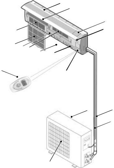
IDENTIFICATION OF PARTS
A |
|
B |
Indoor unit |
R
C
I
M G H
H
E F
L
D
N O
Outdoor unit
P
Q
Indoor unit
A- Air Intake
B- Front Panel
C- Operation Panel
D- Display
E- Air Outlet
F- Vertical Adjustment Louver
G- Horizontal Adjustment Louver
H- Charcoal Filter (optional)
I- Electrostatic Filter (optional)
L- Remote Control
M- Air Filter
Outdoor unit
N- Air Intake
O- Pipes and Power Connection Cord
P- Drain Hose
Note: Condensate water drains at COOLING or DRY operation.
Q- Air Outlet
R- Rating plate (product tecnical data)
NOTE:
The figure above is only a simple presentation of the unit, it may not match the external appearance of the unit you purchased.
139

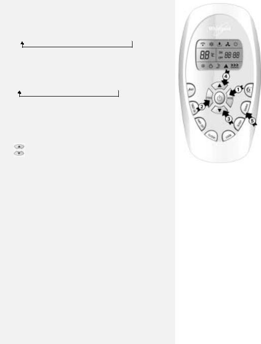
Operating and Display
1
4
2

 3
3
5
1.Emergency button
Used to control the unit when the remote control is out of work. Used to set or cancel auto restart function. (See page 138)
2.Run Indicator (Green)
It is on during operation. When SLEEP mode is set, it will flash for ten seconds, then it will light up. It flashes during defrosting.
3.Timer Indicator (Yellow)
It lights up during the set time.
4.Compressor Indicator (Red)
It lights up when compressor is running.
5.Signal Receptor
Receives signal from the remote control.
Note: The shape and position of the switches and indicators may vary depending on the model, but their function are similar.
140

REMOTE CONTROL
The remote control transmits signals to the system.
A.ON/OFF button: The appliance will be started when it is energized or will be stopped when it is in operation, if you press this button.
B.MODE button: Used to select the operation mode.
C.FAN button: Used to select fan speed in sequence auto, high, medium or low.
D.ROOM TEMPERATURE SETTING buttons: Used to select the room temperature. Used to set time in TIMER mode. Used to set time in TIMER mode and REAL TIME CLOCK
E.SWING button: Used to stop or start vertical adjustment louver swinging and set the desired up/down airflow direction.
F.6th Sense button  : Used to enter fuzzy logic operation directly, regardless of the unit is on or off.
G.TIMER ON/OFF BUTTON: Used to set or cancel the timer operation.
H.SLEEP button  : Used to set or cancel Sleep Mode operation.
I.JET button  : Used to start or stop the fast cooling. (Fast cooling operates at high fan speed with 18°C set temp automatically).
J.LOCK BUTTON: When you press this button, all the buttons are locked and not available. Press again to cancel it.
K.Clock button: Used to enter the current time.
D
I
G
C
K
A F
B
E
H
J
Indication symbols on LCD:
Cooling indicator
Dry indicator
Fan only indicator *Heating indicator
|
|
|
Auto fan speed |
|
|
|
|
|
indicator |
|
|
|
Signal transmit |
|
|
|
|
|
|
|
|
|
|||||
|
|
|
High fan speed |
|
|
|
|
|
SLEEP indicator |
|
|
|
Display set timer |
|
|
|
|
|
|
|
|
|
|||||
|
|
|
|
|
|
|
|
|
|
|
|||
|
|
|
Medium fan speed |
|
|
|
|
|
LOCK indicator |
|
|
|
Display clock |
|
|
|
|
|
|
|
|
||||||
|
|
|
|
|
|
|
|
|
|
|
|||
|
|
|
Low fan speed |
|
|
|
|
|
indicator |
|
|
|
Display set |
|
|
|
|
||||||||||
|
|
|
|
|
|
|
|
||||||
|
|
|
|
|
|
|
|
|
|
|
|||
|
|
|
|
|
|
|
|
|
|
|
|
|
|
|
|
|
|
|
|
|
|
|
|
|
|
|
|
temperature
NOTE: Each mode and relevant function will be further specified in following pages.
How to insert the batteries
• Remove the battery cover in the direction of the arrow.
• Insert new batteries making sure that the (+) and (-) of battery are matched correctly.
•Refit the cover by sliding it back into position.
Note:
•Use 2 LR03 AAA (1.5 V) batteries. Do not use rechargeable batteries. Replace batteries with new ones of the same type when the display becomes dim.
• If the replacement is done within 1 minute, the remote control will keep original presetting. However, if you want to change the presetting from Heat Pump to Cool Only or Cool Only to Heat Pump, you should reload batteries 3 minutes after removing the old ones.
(Please refer to page 138 for details.)
Storage and tips for using the remote control |
Remote control holder |
The remote control can be stored in a holder mounted on the wall. NOTE: The remote control holder is an optional part.
How to use the remote control
To operate the room air conditioner, point the remote control at the signal receiver. The remote control will operate the air conditioner at a distance of up to 7 m when pointing at the signal receiver of the indoor unit.
Choose cooling only remote control or heat pump.
Please refer to page 138 “Preparation before use” for details.
Signal receiver
141
OPERATION INSTRUCTIONS
Operating modes
1.Selecting mode
Each time MODE button is pressed, the operation mode is changed in sequence:
COOLING 
 DRY
DRY 

 FAN ONLY

 HEATING
IMPORTANT:
Heating mode is NOT available for cooling only air conditioner.
2.“FAN” mode
Each time the “FAN” button is pressed, the fan speed is changed in sequence:
AUTO 

 HIGH
HIGH 

 MEDIUM

 LOW
LOW
IMPORTANT:
•In “FAN ONLY” mode, only “High”, “Medium” and “Low” are available.
•In “DRY” mode, airflow is set at “Low” automatically, “FAN” button is ineffective in this case.
3.Setting temperature
Press once to raise temperature setting by 1°C
Press once to lower temperature setting by 1°C
Range of available set temperature:
*HEATING, COOLING |
18°C ~ 32°C |
DRY |
unable to set |
FAN ONLY |
unable to set |
*NOTE: Heating mode is NOT available for cooling only models.
4.Turning on
Press  button, when the appliance receives the signal, the RUN indicator of the indoor unit lights up.
SWING, 6th SENSE, TIMER ON, TIMER OFF, CLOCK, SLEEP and JET operation modes will be specified in the following pages. IMPORTANT:
•Changing modes during operation, sometimes the unit does not response at once. Wait 3 minutes.
•During heating operation, air flow is not discharged at the beginning. After 25minutes, the air flow will be discharged until temperature of indoor heat exchanger rises.
•Wait 3 minutes before restarting the appliance.
Airflow direction control
5.Airflow direction control
Vertical airflow is automatically adjusted to a certain angle in accordance with the operation mode after turning on the unit.
The direction of airflow can also be adjusted to your own requirement by pressing the “SWING” button of the remote control.
operation mode |
direction of airflow |
|
|
COOLING, DRY |
horizontal |
|
|
*HEATING, FAN ONLY |
downward |
|
|
*Heating mode is only available for heat pump models.
142
 Loading...