


TOSHIBA AMERICA INFORMATION SYSTEMS STORAGE DEVICE DIVISION
IRVINE, CALIFORNIA
SD-M1711
DVD-ROM SCSI DRIVE
USER MANUAL

CONTENTS |
|
Introduction.............................................................................. |
1 |
Setup ........................................................................................ |
3 |
Using the DVD-ROM Drive ...................................................... |
7 |
Troubleshooting..................................................................... |
10 |
Specifications ........................................................................ |
11 |
Drive Connectors................................................................... |
15 |

INTRODUCTION – SD-M1711 DVD-ROM Drive
General Features
Tray Loading Mechanism
3-way Disc Eject (eject button, software, emergency eject hole)
Average Random Access Time |
|
CD-ROM |
85ms |
DVD |
105ms |
DVD-RAM |
170ms |
DAE (Digital Audio Extraction) Audio Capability
MPC3 Compatibility
Headphone Output Volume Control
Multi-Read Capability
Regionalization (RPC2 compliance) (DVD)
SCSI BUS Interface:
Types of Disc Formats Supported
DVD
•DVD-ROM
DVD-5 - Single-sided/Single Layer DVD-9 - Single-sided/Dual Layer DVD-10 - Double-sided/Single Layer DVD-18 - Double-sided/Dual Layer
•DVD-R, DVD-RW
1
CD
•CD-DA
•CD+(E)G
•CD-MIDI
•CD-TEXT
•CD-ROM
•CD-ROM-XA
•CD-I Bridge (Photo-CD, Video CD)
•CD-I
•Multi-session (Photo-CD, CD Extra, CD-RW, CD-R)
•CD-R (Read)
•CD-RW (Read)
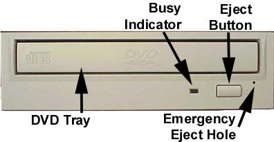
Front Panel
Figure 1.SD-M1711 DVD-ROM Drive Front Panel
Loading Tray
Busy Indicator
Eject
Button
Emergency
Eject Hole
Load disc using tray.
When you install a disc into the DVD-ROM drive, the BUSY light flashes slowly as it attempts to locate the disc. One of the following will occur:
•BUSY light goes out. The DVD-ROM drive is ready to read data from the disc.
•BUSY light flashes slowly. The disc may be dirty.
•BUSY light remains ON. The DVD-ROM is accessing data.
•BUSY light remains ON indefinitely. The DVD-ROM is experiencing an error
The Eject button is used to open the disc tray so you can install or remove a disc.
The emergency eject hole is to be used only when the Loading Tray will not open when Eject button is pressed.

SETUP – SD-M1711 DVD-ROM
The following steps must be performed to properly install your drive:
•Set DVD-ROM Drive Jumper Settings: SCSI ID, Parity, Termination, 512/2K, Power
•Connect Audio Cable
•Attach SCSI Interface Cable
•Attach Power Cable
•Daisy-Chaining SCSI Drives (if applicable)
•Mount Drive
Jumper Settings
Figure 1. Jumper Location
SCSI ID - All SCSI devices attached to your computer are assigned a SCSI-ID number from 0 to 7. Your DVD-ROMs SCSI ID must be set so that its ID number does not conflict with any other devices SCSI-ID in your system. In most cases, your DVDROM will be set to SCSI ID 4 at the factory. Also note that your SCSI interface card in most cases has a SCSI ID of 7. This following chart (figure 3) shows the jumper settings for the eight possible ID numbers
A block of mode select jumpers are located on the rear of the DVD-ROM. If a jumper covers both pins on the jumper block, it is ON; if there is no jumper or only one of the pins is covered, the jumper is OFF. The jumper settings include SCSI ID, Parity, Termination, Block Selectability, Test and Power Supply.
Figure 2. Jumper Block
Figure 3. SCSI ID Examples
Parity - In the OFF mode, the parity bit check function on the SCSI data bus is activated which enhances data bus reliability. Therefore, the jumper should remain in the OFF mode.
3

Terminator ON/OFF - This jumper turns termination power ON or OFF. If you are connecting more than one SCSI device to your system, and the DVD-ROM is not at the end of the chain, then terminator jumper is not required.
512/2K (Block Size Selectability) - This jumper is used to select default block size. When the jumper is present, the default block size equals 512Bytes, when the jumper is not present, the default block size is 2048Bytes. This is effective for CD media only, not DVD media.
Test - This setting selects the drive operation between normal CD-ROM and CD-Audio player mode. When jumper is set to ON position, commands from the host computer are ignored. This jumper is for test purposes only and should be set to OFF for proper CD-ROM function.
Power Supply - Toshiba SCSI DVD-ROM drives can supply power to other equipment on the SCSI BUS. When the jumper is ON, the drive will supply termination power. If you are not sure if any other device supplies termination power, it is fine to leave the jumper ON.
Placing DVD-ROM Drive inside your Computer
Now that you have set the jumpers, you are ready to install your DVD-ROM drive inside your computer.
 Important Note: Disconnect power from your computer system before beginning installation.
Remove computer cover and faceplate if required. Refer to your computer systems manual for removal information. If the DVD-ROM drive is replacing a CD-ROM or DVD-ROM, remove drive presently installed in your system.
Your Toshiba DVD-ROM drive can be placed in any free half-height drive slot at the front of your computer. (It can be mounted horizontally or vertically.)
Carefully start sliding the DVD-ROM drive into the opening with the disc tray facing the front of the computer. Before you push the drive all the way in you will need to connect the IDE BUS cable, Audio cable and the Power cable on the back of the drive.
Connecting Cables
SCSI Interface Cable (not supplied with drive) - The internal SCSI interface cable is connect to your SCSI host adapter card and fits into the socket on the back of your DVD-ROM. The stripe or red-colored side of the ribbon cable connects to pin 1 of the drive's SCSI connector which is found next to the drive's power connector. Carefully push the SCSI connector into the socket, making sure it fits snugly
Power Cable - Connect an internal computer power supply cable to the power socket at the back of the DVDROM drive. One side of the plug has chamfered edges, so the power connector fits only one way. Push plug completely into the socket making sure the plug fits correctly.
Figure 4.Installing Power Cable
4
 Loading...