


 Loading...
Telecommunication Systems Division
TM
External Wireless Handset
User Guide
May 1999

Publication Information
Toshiba America Information Systems, Inc., Telecommunication Systems Division, reserves the right, without prior notice, to revise this information publication for any reason, including, but not limited to, utilization of new advances in the state of technical arts or to simply change the design of this document.
Further, Toshiba America Information Systems, Inc., Telecommunication Systems Division, also reserves the right, without prior notice, to make such changes in equipment design or components as engineering or manufacturing methods may warrant.
DKA-UG-WATEL-VA 4016153
Version A.1, May 1999
Version A, August 1998
© Copyright 1999
Toshiba America Information Systems, Inc. Telecommunication Systems Division
All rights reserved. No part of this manual, covered by the copyrights hereon, may be reproduced in any form or by any means—graphic, electronic, or mechanical, including recording, taping, photocopying, or information retrieval systems—without express written permission of the publisher of this material.
Strata is a registered trademark of Toshiba Corporation. Strata AirLink and Call Center Viewer are trademarks of Toshiba America Information Systems, Inc. Stratagy is a registered trademark of Toshiba America Information Systems, Inc.
Trademarks, registered trademarks, and service marks are the property of their respective owners.

Contents
Introduction |
|
Organization ................................................................................................................ |
iii |
Conventions ................................................................................................................. |
iv |
Related Documents....................................................................................................... |
v |
Chapter 1 – The Grand Tour |
|
Handset ......................................................................................................................... |
2 |
Charger Base................................................................................................................. |
5 |
Chapter 2 – Installation |
|
LCD Low-battery Indicator....................................................................................... |
9 |
Removing and Re-installing the Handset Battery ................................................... |
10 |
Chapter 3 – Features |
|
Powering ON and OFF ............................................................................................... |
14 |
Making and Receiving Calls....................................................................................... |
14 |
Menu Operation .......................................................................................................... |
15 |
Auto Answer............................................................................................................ |
16 |
Change Idle Message............................................................................................... |
17 |
Click Volume .......................................................................................................... |
18 |
Delete Last Number Dialed ..................................................................................... |
18 |
Display Contrast ...................................................................................................... |
19 |
Strata AirLink External Wireless Handset |
i |

Display Test Option................................................................................................. |
20 |
Ringer Type ............................................................................................................. |
20 |
Ringer Volume ........................................................................................................ |
21 |
Time Format ............................................................................................................ |
21 |
Using the Hookswitch (Flash) .................................................................................... |
22 |
Adjusting Volume....................................................................................................... |
23 |
Mute ............................................................................................................................ |
23 |
Locking the Dial Pad .................................................................................................. |
24 |
FCN Feature Access ................................................................................................... |
24 |
Speed Dial................................................................................................................... |
25 |
Appendix....................................................................................................................... |
33 |
Troubleshooting .......................................................................................................... |
33 |
Specifications.............................................................................................................. |
36 |
Index ............................................................................................................................... |
37 |
ii
Strata AirLink External Wireless Handset

Introduction
This guide describes the features and operation of the Strata AirLink External Wireless handset. If you are a new user, you should read this entire guide. It introduces you to all the features and enables you to start working with the wireless handset quickly.
The wireless handset is supported by Strata® DK systems and many nonToshiba systems.
Organization
♦Chapter 1 – The Grand Tour describes the wireless handset, including buttons, icons, and the Charger Base.
♦Chapter 2 – Installation covers proper handset location, charging the batteries, and verifying the assigned system and handset IDs.
♦Chapter 3 – Features describes the basic features of the handset, including menu options and Speed Dial calling by number or name.
♦Appendix covers troubleshooting techniques, range and performance, radio interference, and specifications.
Introduction |
iii |
Conventions ——————————————————————————————————————
Conventions
This guide uses the following conventions:
denotes a procedure
1. |
Actions you |
The immediate response to the action performed |
|
perform appear |
appears in this column. Addtional notes and |
|
in this column. |
comments are also included. |
|
They can |
|
|
consist of |
|
|
either a single |
|
|
step or a series |
|
|
of numbered |
|
|
steps. |
|
2. |
When the |
|
|
action you |
|
|
perform results |
|
|
in a screen, |
|
|
menu, etc., the |
|
|
screen displays |
|
|
to the right. |
|
2765
Note Elaborates specific items or references other information.
Important! Calls attention to important instructions or information.
CAUTION! Advises you that hardware, software applications, or data could be damaged if the instructions are not followed closely.
iv
Strata AirLink External Wireless Handset

—————————————————————————————————— |
Related Documents |
([WUD EROG letters represent telephone buttons. For example:
.
denotes the step in a one-step procedure.
~means “through”. For example: 5 ~ 10.
+is used for multiple key entries.
Example: Press 6SHHG 'LDO + ;; + 5HGLDO + 6SNU
(;; = 08~60 seconds).
see Figure 12 Grey words within the printed text denotes crossreferences. In the electronic version of this manual (Strata DK Library CD-ROM or FYI Internet download), cross-references appear in blue hypertext.
Related Documents
♦The Strata AirLink External Wireless System Installation Guide can be used as a reference for more information.
♦Strata AirLink External Wireless Handset Quick Reference Guide contains instructions for operation of commonly used Strata AirLink External Wireless Handset features.
Introduction |
v |

Related Documents ——————————————————————————————————
vi
Strata AirLink External Wireless Handset

The Grand Tour |
1 |
|
|
Your wireless telephone brings mobility and productivity to office telephones. Greater call access cuts down on “telephone tag” delays, and its compact design makes it easy to take with you.
The wireless telephone was designed and engineered to provide reliability, long life, and outstanding performance. It operates in the range of 1.9 GHz Unlicensed Personal Communication Service (UPCS), which represents state-of-the-art design and engineering.
Your wireless telephone provides unsurpassed range, clarity, and fully-secured communications using scrambled voice information.
The handset comes with one Nickel Metal Hydride (NiMH) battery. When fully charged your handset provides up to 4 hours of talk and 40 hours of standby time.
It also has 12 handset volume adjustments (plus silent), 8 ring levels, and a lockable dial pad.
The Grand Tour |
1 |
Handset ———————————————————————————————————————
You can access up to eight separate telephone systems, because the wireless telephone is capable of storing multiple system IDs. This enables you to move from building to building, system to system.
The handset easily accesses telephone system features, such as Call Forwarding, Call Pickup, and Redial by using )/6+ or )&1.
There are 70 internal Speed Dial memory locations with maximums of 8 characters for names and 30 characters for numbers, so that you can Speed Dial by name or code.
Handset
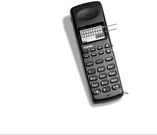
Your wireless handset (shown at right) stores up to eight system and handset IDs that are configured by your System Administrator.
The handset has a two-line Liquid Crystal Display (LCD) that show alphanumeric information, including the idle message, date, call duration, and icons with specific call activity.
Table 1 briefly describes the functions of the LCD fields and the buttons.
Idle Message
Date

 Time/Call Duration
 Icon Display Area
 Volume/Scroll Buttons
PWR
END
CALL
Scroll/Lock Buttons
Important! Do not make changes to system and handset IDs without contacting your System Administrator.
2 |
Strata AirLink External Wireless Handset |
———————————————————————————————————————— |
Handset |
|||
Table 1 |
LCD Fields and Button Descriptions |
|
||
|
|
|
|
|
|
|
Handset |
Description |
|
|
|
|
|
|
|
|
Idle Message |
Displays an idle message. |
|
|
|
|
|
|
|
|
Date |
Displays the current date. |
|
LCD Fields |
|
|
|
|
|
Time/Call Duration |
Displays the call duration. |
|
|
|
|
|
||
|
|
|
|
|
|
|
Icon Display Area |
Displays icons that represent different battery and |
|
|
|
handset conditions. |
|
|
|
|
|
|
|
|
|
|
|
|
|
|
3:5 |
Turns the power ON and OFF. |
|
|
|
|
|
|
|
|
)/6+ |
Performs hookflash functions. |
|
|
|
|
|
|
|
|
|
Enables features with the use of other buttons; for |
|
|
|
)&1 |
example, Call Forward, Transfer, Speed Dial, and |
|
|
|
|
Conference. |
|
|
|
|
|
|
|
|
▲ |
Increases listening volume and scrolls forward through |
|
|
|
menu options. |
|
|
|
|
|
|
|
|
|
|
|
|
|
|
▼ |
Decreases listening volume and scrolls backward |
|
|
|
through menu options. |
|
|
|
|
|
|
|
|
|
|
|
|
|
|
$%& |
Toggles handset between alpha and numeric modes. |
|
Buttons |
|
|
|
|
|
5&/ |
Recalls numbers stored in memory. |
|
|
|
|
|
||
|
|
|
|
|
|
|
672 |
Stores Speed Dial numbers/names and the idle |
|
|
|
message. |
|
|
|
|
|
|
|
|
|
|
|
|
|
|
&$// |
Places the handset off-hook to enable calling. |
|
|
|
|
|
|
|
|
(1' |
Places the handset on-hook and exits from 5&/, |
|
|
|
)&1, 672, and $%& modes. |
|
|
|
|
|
|
|
|
|
|
|
|
|
|
&/5 |
Erases one or more digits in the display. |
|
|
|
|
|
|
|
|
|
Scrolls backwards through the Speed Dial list. |
|
|
|
|
|
|
|
|
|
Scrolls forward through the Speed Dial list and locks/ |
|
|
|
unlocks the dial pad. |
|
|
|
|
|
|
|
|
|
|
|
|
The Grand Tour |
3 |
Handset ———————————————————————————————————————
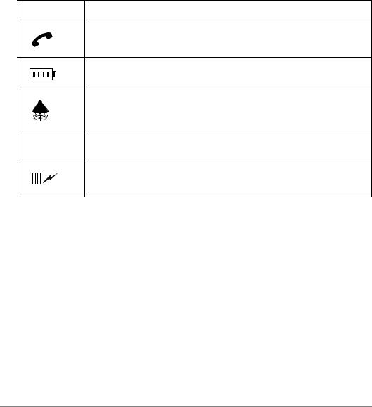
The handset icons that display in the LCD area represent different conditions. Some icons display consistently while others appear under certain conditions.
Table 2 Handset Icon Description
Icon |
Description |
|
|
The handset is off-hook or ringing.
The battery strength is low, medium, or high—one bar is low and four is high.
The handset is ringing. The bars beneath the bell indicate the currently configured ring volume.
ABC
The handset is in alpha mode—you can use the dial pad to enter letters in the display.
The handset is locked onto a base station. The number of bars indicate signal strength. You can make and receive calls only when the lock icon is on.
4 |
Strata AirLink External Wireless Handset |
————————————————————————————————————— |
Charger Base |
Charger Base
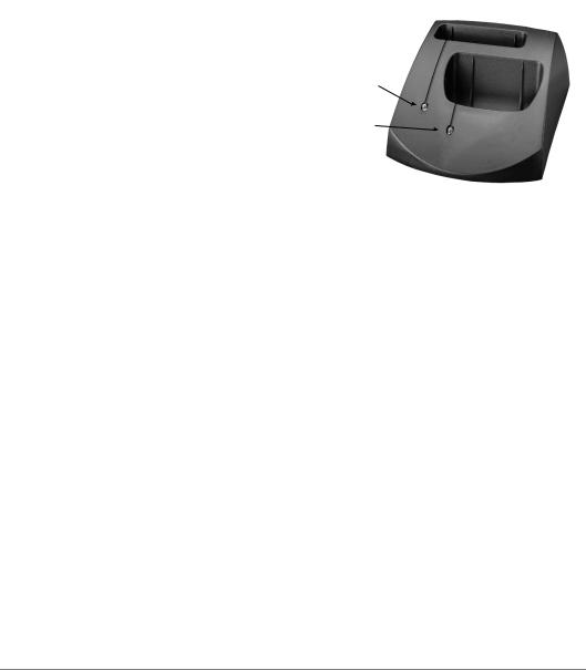
The handset comes with a charger base (shown at the right). The rear slot of the charger is for the spare battery and automatically starts its discharge function when it detects that discharging is necessary.
The front slot functions as a cradle for the handset and a charger for the handset battery. It provides rapid charging only.
The unit has LEDs that indicate battery status while charging. The LEDs flash and use the colors red, green, and amber to indicate different conditions (shown in Table 3).
Battery LED
Handset LED
2959
Table 3 |
LED Indications |
|
||
|
|
|
|
|
|
Color |
State |
Description |
|
|
|
|
|
|
|
|
|
Steady |
Battery is rapid charging. |
|
Red |
|
|
|
|
|
Flashing |
Internal battery fault; battery unusable. Try charging the |
|
|
|
|
||
|
|
|
battery again. If the problem persists, replace the battery. |
|
|
|
|
|
|
|
|
|
|
|
|
|
|
Steady |
Battery is charged. |
|
|
|
|
|
|
Green |
|
|
Battery is charged, but standby/talk time may be reduced. |
|
|
|
Flashing |
Repeated rapid charging may rejuvenate the battery. If not, |
|
|
|
|
replace the battery. |
|
|
|
|
|
|
|
|
Steady |
Charger is evaluating the state of the handset or battery, or |
|
|
|
waiting for one battery to complete charging. |
|
|
|
|
|
|
|
Amber |
|
|
|
|
|
|
Short circuit or over-discharged battery is detected. Make |
|
|
|
|
|
|
|
|
|
Flashing |
sure contacts are clean and leave the battery in the |
|
|
|
|
charger until rapid charging starts and completes. |
|
|
|
|
|
|
Amber/Green |
Alternate |
Battery is discharging. |
|
|
Flashing |
|||
|
|
|
|
|
|
|
|
|
|
The Grand Tour |
5 |

Charger Base —————————————————————————————————————
6 |
Strata AirLink External Wireless Handset |

Installation |
2 |
|
|
This chapter describes installation procedures, including charging the batteries for your wireless telephone.
Important! Your wireless telephone system must be programmed before the handset operates. Please see your System Administrator for more information.
Step 1: Select Location
1.Select a location for your handset and charger base. Avoid excessive heat or humidity.
2.Place them on a desk or tabletop near a standard 120VAC outlet.
3.Keep the handset away from sources of electrical noise (motors, fluorescent lighting, etc.)
Installation |
7 |
Loading...