


SD-43HK
DVD HOME
CINEMA SYSTEM
SD-43HK
OWNER’S MANUAL
Before connecting, operating or adjusting this product, pleas
read this instruction booklet carefully and completely.
V I D E O
COMPACT
DIGITAL AUDIO
COMPACT
DIGITAL VIDEO
AH68-01289C
Precautions
1 2
Safety Warnings
Use of controls, adjustments or performance of procedures other
than those specified herein may result in hazardous radiation
exposure.
CAUTION-INVISIBLE LASER RADIATION WHEN OPEN
AND INTERLOCKS DEFEATED, AVOID EXPO-
SURE TO BEAM.
This symbol indicates that dangerous voltage which
can cause electric shock is present inside this unit.
This symbol alerts you to important operating and
maintenance instructions accompanying the unit.
WARNING: To reduce the risk of fire or electric shock, do not
expose this appliance to rain or moisture.
Wiring the Main Power Supply Plug(UK Only)
IMPORTANT NOTICE
The main lead on this equipment is supplied with a moulded plug incorporating a fuse. The value of the fuse is indicated on the pin
face of the plug and if it requires replacing, a fuse approved to BS1362 of the same rating must be used.
Never use the plug with the fuse cover removed. If the cover is detachable and a replacement is required, it must be of the same
colour as the fuse fitted in the plug. Replacement covers are available from your dealer.
If the fitted plug is not suitable for the power points in your house or the cable is not long enough to reach a power point, you
should obtain a suitable safety approved extension lead or consult your dealer for assistance.
However, if there is no alternative to cutting off the plug, remove the fuse and then safely dispose of the plug. Do not connect the
plug to a main socket as there is a risk of shock hazard from the bared flexible cord.
Never attempt to insert bare wires directly into a main socket. Aplug and fuse must be used at all times.
IMPORTANT
The wires in the main lead are coloured in accordance with the following code:–
BLUE = NEUTRAL BROWN = LIVE
As these colours may not correspond to the coloured markings identifying the terminals in your plug, proceed as fol-
lows:–
The wire coloured BLUE must be connected to the terminal marked with the letter N or coloured BLUE or BLACK.
The wire coloured BROWN must be connected to the terminal marked with the letter L or coloured BROWN or RED.
WARNING: DO NOT CONNECT EITHER WIRE TO THE EARTH TERMINAL WHICH IS MARKED WITH
THE LETTER E OR BY THE EARTH SYMBOL , OR COLOURED GREEN OR GREEN
AND YELLOW.
CLASS 1 LASER PRODUCT
KLASSE 1 LASER PRODUKT
LUOKAN 1 LASER LAITE
KLASS 1 LASER APPARAT
PRODUCTO LASER CLASE 1
RISK OF ELECTRIC SHOCK.
DO NOT OPEN
CAUTION:
TO REDUCE THE RISK OF ELECTRIC SHOCK, DO NOT
REMOVE REAR COVER. NO USER SERVICEABLE
PARTS INSIDE. REFER SERVICING TO QUALIFIED
SERVICE PERSONNEL.
CLASS 1 LASER PRODUCT
This Compact Disc player is classified
as a CLASS 1 LASER product.
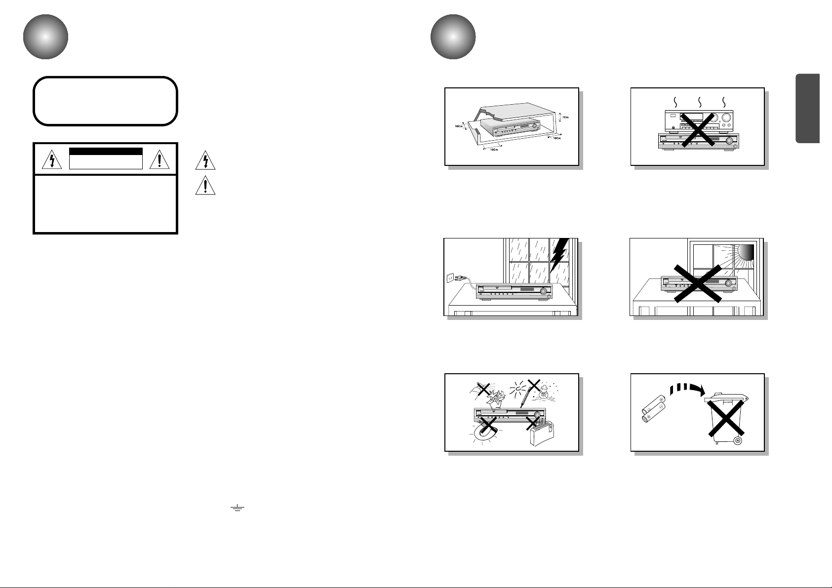
CAUTION
Ensure that the AC power supply in your house complies with the identification sticker located on the back of your player. Install your
player horizontally, on a suitable base (furniture), with enough space around it for ventilation (3~4inches). Make sure the ventilation
slots are not covered. Do not stack anything on top of the player. Do not place the player on amplifiers or other equipment which may
become hot. Before moving the player, ensure the disc tray is empty. This player is designed for continuous use. Switching off the DVD
player to the stand-by mode does not disconnect the electrical supply. In order to disconnect the player completely from the power sup-
ply, remove the main plug from the wall outlet, especially when left unused for a long period of time.
Protect the player from moisture(i.e. vases) , and excess heat(e.g.fire-
place) or equipment creating strong magnetic or electric fields (i.e.speak-
ers...). Disconnect the power cable from the AC supply if the player mal-
functions. Your player is not intended for industrial use.
Use of this product is for personal use only.
Condensation may occur if your player or disc have been stored in cold
temperatures.
If transporting the player during the winter, wait approximately 2 hours
until the unit has reached room temperature before using.
Phones
During thunderstorms, disconnect AC main plug from the
wall outlet.
Voltage peaks due to lightning could damage the unit.
Do not expose the unit to direct sunlight or other heat
sources.
This could lead to overheating and malfunction of the unit.
The battery used with this product contain chemicals that
are harmful to the environment.
Do not dispose of batteries in the general household
trash.
PREPARATION
PREPARATION CONNECTIONS
OPERATION
SETUP
MISCELLANEOUS
RADIO OPERATION
Before Use
3
Contents
3
PREPARATION
Safety Warnings..........................................................................................................................................1
Precautions..................................................................................................................................................2
Before Use ..................................................................................................................................................4
Description .................................................................................................................................................5
Remote Control...........................................................................................................................................7
CONNECTIONS
Connecting the Speakers ............................................................................................................................9
Connecting the FM and AM(MW/LW) Antennas .........................................................................................10
Connecting to a TV .....................................................................................................................................11
Connecting the Optical Equipment..............................................................................................................13
Before Using the DVD Player ....................................................................................................................14
OPERATION
DVD Playback ............................................................................................................................................15
MP3/WMA CD Playback..............................................................................................................................17
Forward/Reverse Searching........................................................................................................................19
Slow Playback/Checking the Remaining Time............................................................................................20
Repeat Playback ........................................................................................................................................21
Disc Menu/Top Menu Function....................................................................................................................22
Selecting the Audio Language/Subtitle Language......................................................................................23
Zoom/Angle Functions ................................................................................................................................24
JPEG File Playback.....................................................................................................................................25
Program Playback.......................................................................................................................................27
SETUP
Setup Functions ..........................................................................................................................................29
Speaker Setup.............................................................................................................................................33
To set up Speaker Balance.........................................................................................................................35
Creating Realistic Sound Fields..................................................................................................................36
Dolby Pro Logic II decoder..........................................................................................................................37
RADIO OPERATION
Listening to the Radio .................................................................................................................................39
Presetting the radio stations........................................................................................................................40
About RDS broadcasting.............................................................................................................................41
MISCELLANEOUS
Sleep Function ............................................................................................................................................43
Using Headphone Jack...............................................................................................................................43
Mute Function..............................................................................................................................................43
Cautions on Handling and Storing Discs ....................................................................................................44
Troubleshooting ..........................................................................................................................................45
Language Code List....................................................................................................................................46
Specifications ..............................................................................................................................................47
Memo...........................................................................................................................................................48
COMPACT
DIGITAL VIDEO
V I D E O
COMPACT
DIGITAL AUDIO
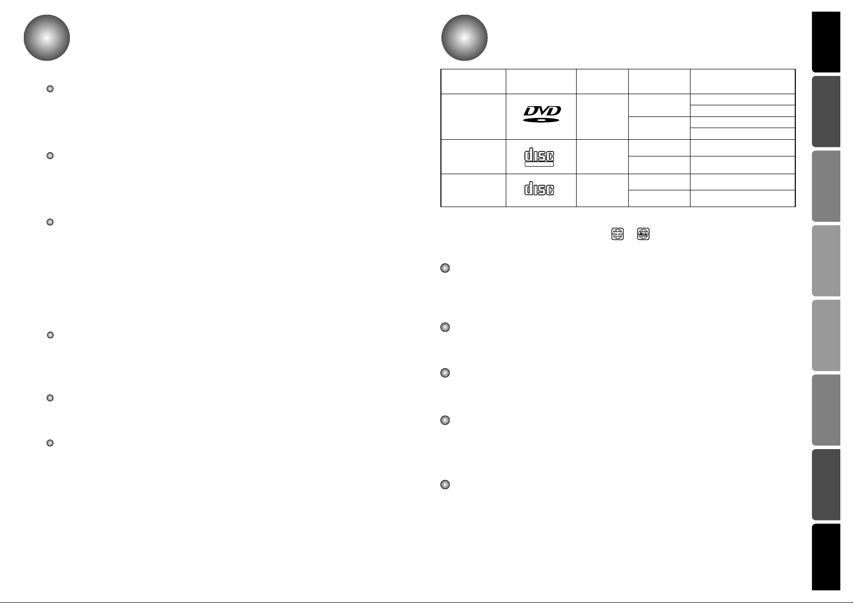
Marks
Audio + Video
DVD
VIDEO-CD
AUDIO-CD
12 cm
Approx. 240 min. (Single-sided)
Approx. 480 min. (Double-sided)
Approx. 80 min. (Single-sided)
Approx. 160 min. (Double-sided)
74 min.
20 min.
74 min.
20 min.
8 cm
12 cm
8 cm
12 cm
8 cm
Audio + Video
Audio
44
Recording
Types
Disc Types
Disc Size
Max. Playing Time
Notes
– Depending on the conditions of the recording equipment or the CD-R/RW disc itself, some CD-R/RW
discs cannot be played on the unit.
– The unit cannot play the CD-R/RW discs that contain no data, or contain different kinds of formatted
data other than MP3 and CD-DA data.
– Do not attach any seal or label to either side (the labeled side or the recorded side) of a disc.
– Do not use irregular shaped CDs (e.g., heart-shaped or octagonal). It may result in malfunctions.
– Playback of some DVD-R/RW discs may not be possible depending on the conditions of the recording
or the severity of scratches on the disc surface.
Notes on DVDs and Video CDs
Some playback operations of DVDs and Video CDs may be intentionally fixed by software manufactur-
ers.
As this unit plays DVDs and Video CDs according to disc content designed by the software manufactur-
er, some playback features of the unit may not be available, or other functions may be added.
Refer also to the instructions supplied with the DVDs and Video CDs. Some DVDs made for business
Note on DTS-encoded CDs
When playing DTS-encoded CDs, excessive noise may be exhibited from the analog stereo output.
To avoid possible damage to the audio system, turn down the volume before playing back such discs,
adjust the volume gradually, and keep the volume level low. To enjoy DTS Digital Surround TM play-
back, an external 5.1 channel DTS Digital Surround TM decoder system must be connected to the digital
output of the unit.
DVD players and the discs are coded by region. These regional codes must match in order for the disc
to play. If the codes do not match, the disc will not play.
The Region Number for this player is given on the rear panel of the player.
(Your DVD player will only play DVDs that are labeled with identical region codes.)
Because of problems and errors that can occur during the creation of DVD software and or the manufacture
of DVD discs, Toshiba cannot guarantee that this player will play every feature of every DVD bearing the DVD
logo. As one of the creators of DVD technology. Toshiba DVD players are manufactured to the highest stan-
dards of quality and, as a result, such incompatibilities are very rare.
The region number of this DVD Home Theater is 2. If region numbers,which stand for their playable area, are
printed on your DVD Video Disc and you do not find or , disc playback will not be allowed by the
DVD Home Theater.
2
PREPARATION
65
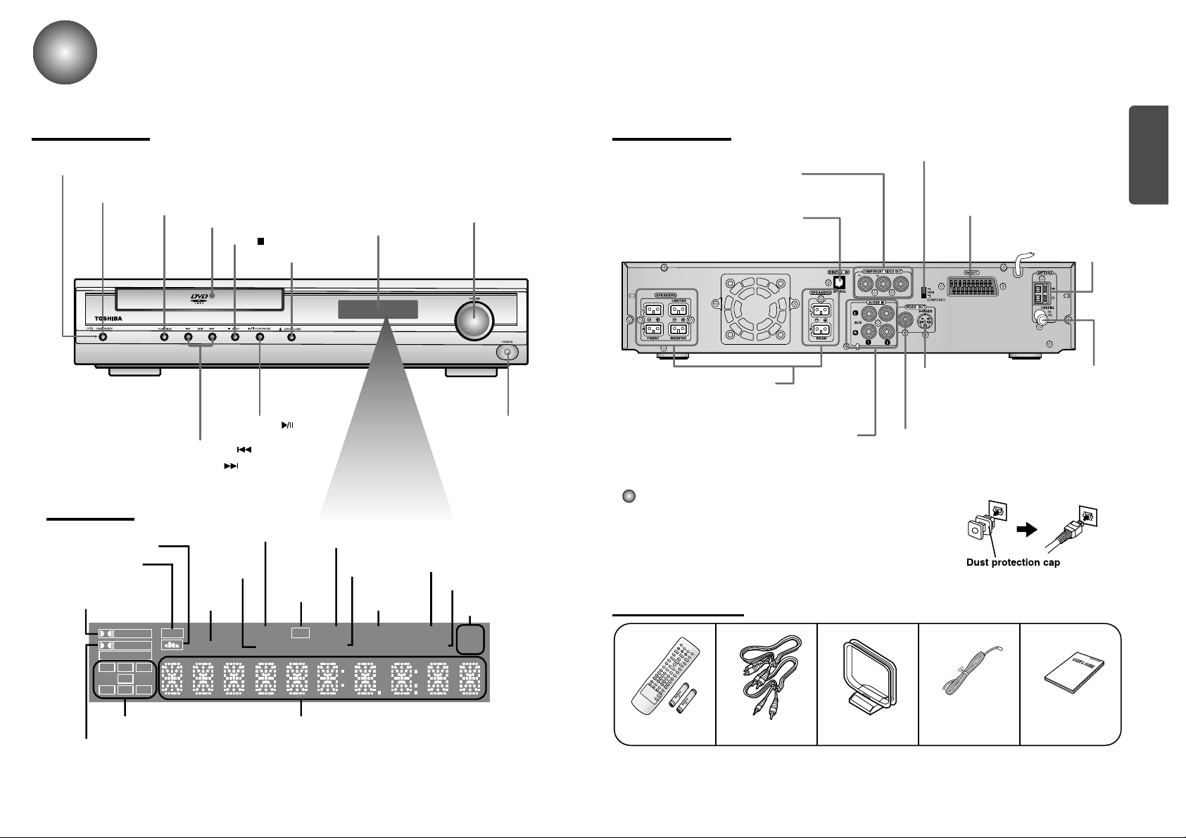
Description
Front Panel
Remote Control &
Batteries
Audio Cable/
Video Cable
User's ManualFM AntennaAM Antenna
VOLUME CONTROL
STOP ( ) button
ON/STANDBY button
ON/STANDBY indicator
HEADPHONE JACK
DISPLAY
FUNCTION button
DISC TRAY
OPEN/CLOSE button
TUNING DOWN & SKIP ( ) buttons
TUNING UP & SKIP ( ) buttons
Y
5.1 Channel Speaker
Output Terminals
COMPONENT VIDEO OUTPUT jacks
Connect a TV with component
video inputs to these jacks.
External Digital Component Input
Connector
Use this to connect external equipment
capable of digital output.
Video Output Connector
Connect the TV's video input jacks (VIDEO IN)
to the VIDEO OUT connector.
S-Video Output Connector
If the TV is equipped with an S-Video
input connector (S-VIDEO IN), connect it
to the player's S-Video output jack.
External Audio Component
Input Connector
AM Antenna
Connector
DTS Disc indicator
MPEG indicator
TITLE
indicator
PRO LOGIC MPEG
LINEAR PCM
TITLE
TUNED
INFO
NEWS
RDS
PROGRAM PBC
MHZ
KHZ
DSP
ST
LCR
LS
LFE
SRS
D I G I T A L
STEREO
indicator
DSP indicator
RADIO FREQUENCY
indicator
PROGRAM
indicator
INFO indicator
NEWS
indicator
System Status DisplaySPEAKER indicator
DOLBY DIGITAL indicator
PRO LOGIC
indicator
TUNER indicator
RDS
indicator
PBC indi-
cator
Dust protection cap
Remove the dust protection cap from the OPTICAL DIGITAL IN
jack and connect the optical digital cable (not supplied) securely
so that the configurations of both the cable and the connector
match. Keep the dust protection cap and always reattach the cap
when not using the connector to protect against dust intrusion.
FM Antenna
Connector
PLAY/PAUSE ( ) button
Rear Panel
Accessories
Display
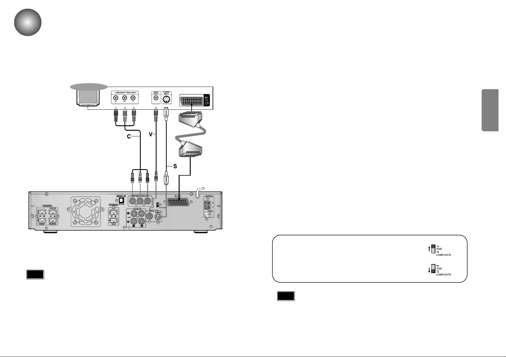
VIDEO OUT SELECT SWITCH
Use the switch to set video out
SCART JACK
Connect to a TV with scart input jack.
PREPARATION
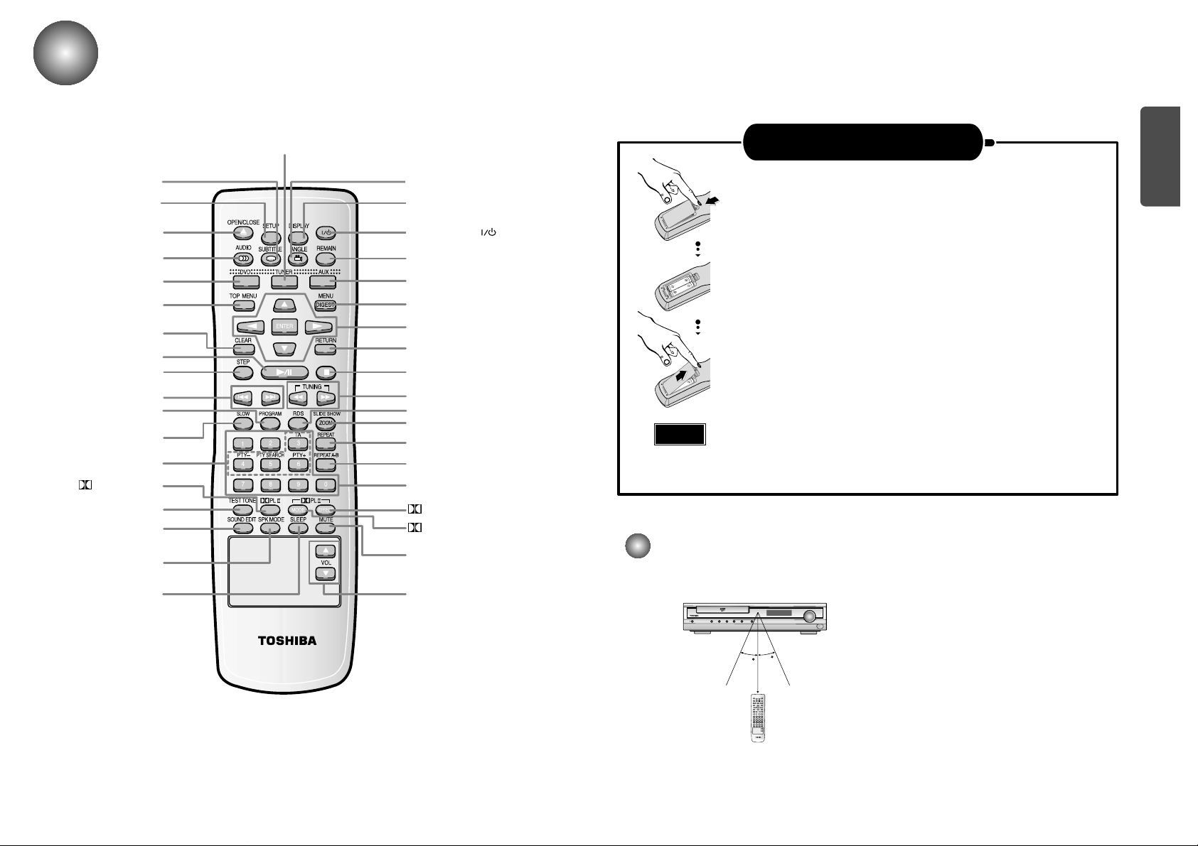
Remote Control
7 8
ON/STANDBY ( ) button
DISPLAY button
REMAIN button
AUX button
MENU/DIGEST button
DIRECTION/ENTER button
RETURN button
STOP button
TUNING/CD Search button
RDS button
SLIDE SHOW/ZOOM button
REPEAT button
NUMBER(0~9) buttons
DPL II EFFECT button
DPL II MODE button
MUTE button
VOLUME Control button
SLEEP button
SPK MODE button
SOUND EDIT button
TEST TONE button
DPL II button
SLOW button
PROGRAM button
UNING PRESET/CD SKIP button
STEP button
PLAY/PAUSE button
CLEAR button
TOP MENU button
DVD button
AUDIO button
OPEN/CLOSE button
SETUP button
REPEAT A↔B button
30
30
7~10m
Open the battery cover on the back of the remote control.
Insert Remote Batteries
Range of Operation of the Remote Control
1
Insert two 1.5V AAbatteries, paying attention to the correct
polarities (+ and –).
2
Replace the battery cover.
3
The remote control can be used up to approximately 23 feet/7 meters in a straight line. It can also be
operated at a horizontal angle of up to 30° from the remote control sensor.
Follow these precautions to avoid leaking or cracking cells:
• Place batteries in the remote control so they match the polarity:(+) to (+)and (–)to (–).
• Use the correct type of batteries.Batteries that look similar may differ in voltage.
• Always replace both batteries at the same time.
• Do not expose batteries to heat or flame.
TUNER button
Caution
SUBTITLE button
ANGLE button
RDS Selection button
Y
9
Connecting the Speakers
10
Rear speaker
(Right Surround)
Right front speaker
Left front speaker
Rear speaker
(Left Surround)
Subwoofer
Turn off the Power first and set the volume knob to low initially before connecting.
•
Connect the speakers using the supplied speaker
cords by matching the colors of the terminals and
those of the cords.
•
To obtain the best possible surround sound, adjust
the speaker parameters (distance, level, etc.).
Center speaker
CONNECTIONS
Ideal Speaker Placement
Front Speakers
Center Speaker
Rear Speakers
Subwoofer Speaker
Set the front speakers so that their tweeters
(high-range) are aligned at about ear level and at a
horizontal angle of 45° to the prime listening position.
Ideally the center speaker should be positioned with
its top surface flush with the front speakers. However,
you may place the speaker either on top or near the
bottom of your TV set.
Place the subwoofer at any convenient location
within the vicinity of the listening position.
Set the rear speakers further back, parallel to the
walls, at 60 to 90 centimeters (2 to 3 feet) above
prime listening position ear level.
If the space behind the listening position is insufficient
(i.e., too close to the wall), place the rear speakers
facing each other on either side.
•
Be sure to match the speaker cord to the appropriate terminal on the components: + to + and
– to –. If the cords are reversed, the sound will be distorted and will lack bass.
•
If you use front speakers with low maximum input rating, adjust the volume carefully to avoid
excessive output on the speakers.
•
Do not disassemble the front cover of supplied speaker.
Note
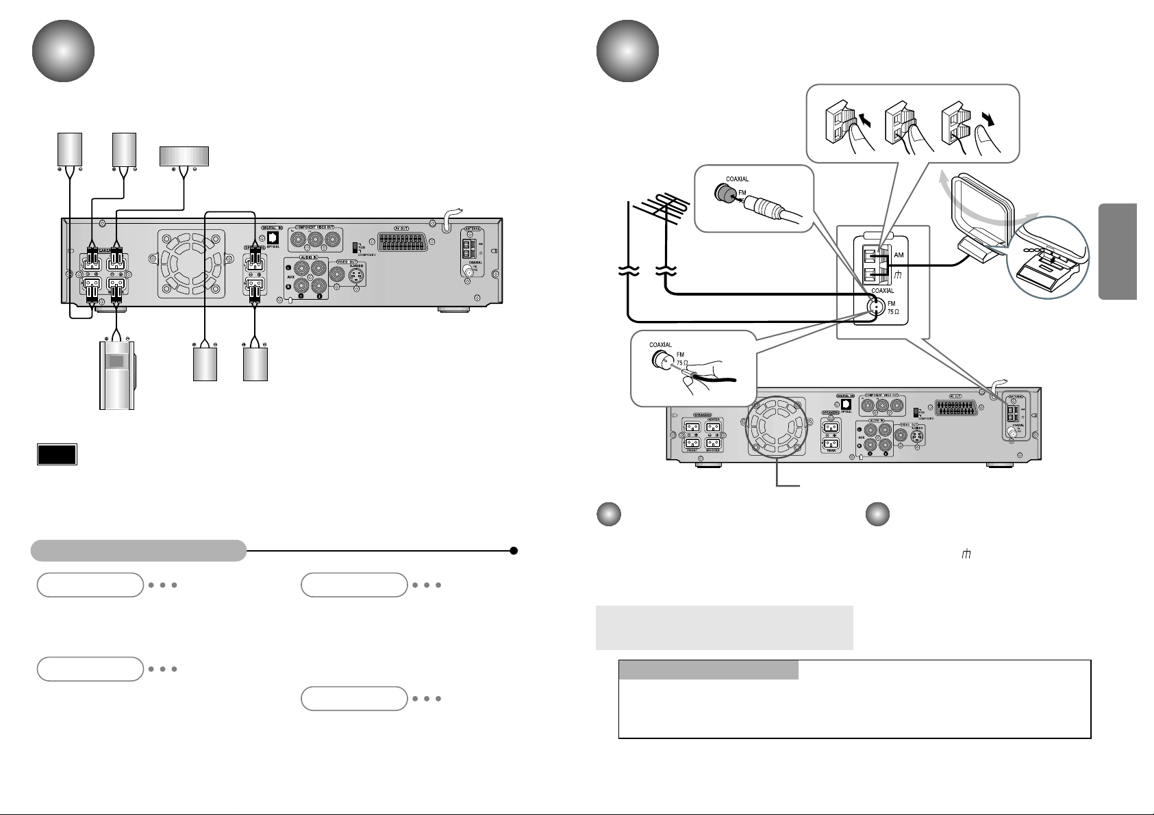
FM antenna connection
1. Connect the FM antenna supplied to the FM
75
Ω
COAXIAL terminal as temporary measure.
2. Slowly move the antenna wire around until you
find a location where reception is good, then
fasten it to a wall or other rigid surface.
•
If reception is poor, connect an outdoor antenna.
Before attaching a 75
Ω
coaxial cable (with a standard
type connector), disconnect the supplied FM antenna.
AM(MW) antenna connection
1. Connect the AM loop antenna supplied
to the AM and terminals.
2. If reception is poor, connect an outdoor
single vinyl-covered wire to the AM ter-
minal. (Keep the AM loop antenna con-
nected).
Connecting the FM and AM
(
MW
)
Antennas
A cooling fan is mounted on the rear panel of the center unit to
prevent abnormal temperature inside the center unit, thus assuring
normal operation. The cooling fan automatically starts rotating to
supply external cool air to the inside of the center unit when the
internal temperature exceeds the specified limit.
For safety, observe the following carefully.
• Make sure there is good ventilation around the center unit. Poor
ventilation could overheat and cause damage.
• DO NOT block the cooling fan and the ventilation openings or
holes. (If they are blocked by a newspaper or cloth, etc., the heat
may not be able to escape.)
Snap the tabs on the loop into the
slots of the base to assemble the
AM loop antenna.
Cooling fan (See “About Cooling Fan” below.)
Y
ANTENNA
123
If FM reception is poor,
connect an outdoor FM antenna
(not supplied).
FM Antenna (supplied)
AM Loop Antenna
(supplied)
If AM reception is
poor, connect an
outdoor AM
antenna(not
supplied).
(About the cooling fan)
CONNECTIONS
1211
•
The signal of S-VIDEO OUT jack will output only when the function mode is selected to CD/DVD.
• On the rear panel SCART cable is indicated as “AV OUT.”
Note
For using the SCART cable
• If Scart is equipped for your TV, set RGB-COMPOSITE
selector of the center unit to RGB. You can get a better picture
quality by using Scart setting.
• If Scart (RGB Input) is not equipped for your TV, set RGB-
COMPOSITE selector to COMPOSITE.
Connecting to a TV
Depending on your TV and other equipment you wish to connect, there are various ways you could
connect the player. Use one of the connections described below.
Video connection (Good)
•
Connect the VIDEO OUT jack on the DVD Receiver to the video in jack on the TV using
the video cable supplied (V).
S-Video connection (Better)
•
Connect the S-VIDEO OUT jack on the DVD Receiver to the S-Video in jack on the TV
using the optional S-Video cable (S).
Component Video (Color Stream®) connection (Best)
•
Connect the COMPONENT VIDEO OUT jacks on the DVD Receiver to the corresponding
in jacks on the TV using an optional Y Pb Pr cable (C).
Scart connection (Best)
If you television is equipped with an SCART input, connect an Scart Jack (not supplied)
from the AV OUT jack on the back panel of the system to the SCART IN jack on your
television.
Y
Rear of TV
SCART
IN
The video output of this unit may vary depending on the TV video format (NTSC or PAL) in use.
• In PAL mode: Video signals can be output through RGB (SCART) and Composite Video only.
• In NTSC mode: Video signals can be output through Component Video (Y/Pb/Pr), Composite Video,
and S-Video.
Please turn off the Power of your TV, DVD receiver and other equipment before doing
any connections. Set the volume to low initially.
Note
CONNECTIONS
•
When the power is not turned on, press down the STOP ( ) button on the main unit
for over 5 seconds.
The product will be initialized to its optimum state.
•
Some operational features such as the Speaker mode, Test tone, Volume, etc. will not
be displayed on the TV screen.
Before Using the DVD Player
14
Your DVD player is capable of playing DVD, VCD, and CD discs.
User instructions may vary depending on the type of disc. Read the instructions
carefully before use.
TV Broadcast System
• This device is designed to work with the PAL video format.
• To change the TV broadcast system to be output, press the ZOOM button while
the power is turned off. The selection will switch between NTSC and PAL each
time you press the button.
• For normal playback, the video format a DVD disc is recorded in must coincide
with your TV's video format.
13
About the symbol display
• “ ” may appear on the TV screen during operation.
This icon means the function explained in this owner’s manual is not available on
that specific DVD video disc.
Note
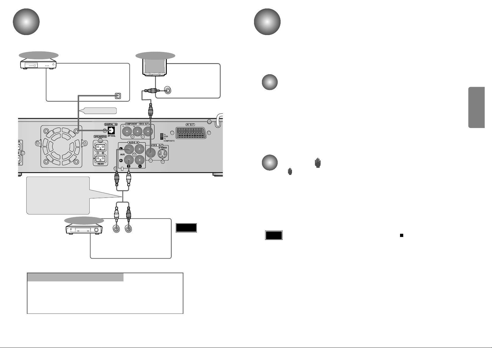
Connecting the Optical Equipment
Y
LR
DIGITAL OUT
VIDEO IN
External Digital
Components
External Analog
Components
Audio Cable (Red/White)
If the external analog
component has only one
output jack, you may connect
either L or R.
For connection to external
equipment with digital output.
Example: CD recorders, MD (Mini Disc) D/A
converters or other components equipped
with digital output jacks
Connect to external equipment with
analog output.
Example: VCR, TV, etc.
•
Always connect the video
and audio connection
cables to the equivalent
colored jack.
Press AUX on the remote control to select DIGITAL IN, AUX1, or AUX2.
Press Function on the main unit to select DIGITAL IN, AUX1, or AUX2.
•
Each time the button is pressed the mode switches as follows: FM ➞ AM(MW) ➞
DVD/CD ➞ DIGITAL IN ➞ AUX 1 ➞ AUX 2.
To Play External Digital/Analog Equipment
Optical Cable
(not supplied)
To view pictures from
external input , first con-
nect the VIDEO IN jack
and then connect the
VIDEO OUT jack.
TV
Warning
 Loading...