


 Loading...
FILE NO. SVM-10049
SERVICE MANUAL
AIR CONDITIONER
SPLIT WALL TYPE
RAS-24SKP-ES2 / RAS-24SA-ES2 RAS-24SKHP-ES2 / RAS-24S2AH-ES2
April, 2010
FILE NO. SVM-10049
CONTENTS
1.SPECIFICATIONS
2.CONSTRUCTION VIEWS
2-1 Indoor Unit
2-2 Outdoor Unit
3.WIRING DIAGRAM
3-1 RAS-24SKP-ES2 / RAS-24SA-ES2 3-2 RAS-24SKHP-ES2 / RAS-24S2AH-ES2
4.SPECIFICATION OF ELECTRICAL PARTS
4-1 Indoor Unit (RAS-24SKP-ES2) 4-2 Outdoor Unit (RAS-24SA-ES2) 4-3 Indoor Unit (RASP-24SKHP-ES2) 4-4 Outdoor Unit (RAS-24S2AH-ES2)
5.REFRIGERATION CYCLE DIAGRAM
5-1 RAS-24SKP-ES2 / RAS-24SA-ES2 5-2 RAS-24SKHP-ES2 / RAS-24S2AH-ES2
6.CONTROL BLOCK DIAGRAM
6-1 RAS-24SKP-ES / RAS-24SA-ES2
6-2 RAS-24SKHP-ES2 / RAS-24S2AH-ES2
7.OPERATION DESCRIPTION
7-1 Remote control
7-2 Outline of Air Conditioner Control
7-3 Description of Operation Circuit
7-4 Description of Safety and Reliability Prevention Function 7-5 One-Touch Operation
7-6 Hi POWER Operation
7-7 QUIET Operation
7-8 ECO Operation
7-9 COMFORT SLEEP Operation
7-10 FILTER Check lamp
7-11 Auto Restart Function
7-12 Self-Cleaning Operation
– 1 –
FILE NO. SVM-10049
8.INSTALLATION PROCEDURE
8-1 Safety Cautions
8-2 Installation Diagram of Indoor and Outdoor Units 8-3 Installation
8-4 Indoor Unit
8-5 Outdoor Unit
8-6 Test Operation
9.TROUBLESHOOTING CHART
9-1 Troubleshooting Procedure
9-2 Basic Check Items
9-3 Primary Judgement
9-4 Self-Diagnosis by Remote Control (Check Code) 9-5 How To Diagnose Faulty Parts
9-6 Troubleshooting for Indoor unit
9-7 Troubleshooting for Wiring (Interconnect cable and Serial Signal Wire) 9-8 Troubleshooting for P.C. Board
9-9 Troubleshooting for Remote Control
10.HOW TO REPLACE THE MAIN PARTS
10-1 Indoor Unit
10-2 Outdoor Unit
11.EXPLODED VIEWS AND PARTS LIST
11-1 Indoor Unit (E - Parts Assy)
11-2 Indoor Unit
11-3 Outdoor Unit (RAS-24SA-ES2) 11-4 Outdoor Unit (RAS-24S2AH-ES2)
− 2 −
FILE NO. SVM-10049
1. SPECIFICATIONS
|
MODEL |
|
RAS-24SKP-ES2 |
|
|
|
|
|
RAS-24SA-ES2 |
ITEM |
|
|
|
Cooling |
Capacity |
|
|
220V |
240V |
|
kW |
6.80 |
6.85 |
|
|
|
|||
|
|
Phase |
|
1 |
Power source |
|
V |
|
220 - 240 |
|
|
Hz |
|
50 |
Power consumption |
|
W |
2030 |
2070 |
Power factor |
|
% |
98 |
97 |
Running |
|
A |
0.3/9.1 |
0.3/8.6 |
Current |
Indoor/Outdoor |
|
||
|
|
|
||
Starting current |
|
A |
|
55 |
Moisture removal |
|
lit/h |
|
2.7 |
Noise |
Indoor (H/M+/M/L+/L) |
dB |
|
50/48/46/43/40 |
|
Outdoor (220-240V) |
dB |
56 |
57 |
Refrigerant |
Name of refrigerant |
|
|
R410A |
|
Rated amount |
kg |
|
1.90 |
Refrigerant control |
|
|
|
Capillary tube |
Interconnection |
Gas side size |
mm |
|
12.7 |
pipe |
Connection type |
|
|
Flare connection |
|
Liquid side size |
mm |
|
6.35 |
|
Connection type |
|
|
Flare connection |
|
Maximum length |
m |
|
15*1 |
|
(One way) |
|
|
25*2 |
|
Maximum height |
m |
|
10 |
|
difference |
|
|
|
|
|
|
|
|
INDOOR UNIT |
|
|
|
RAS-24SKP-ES2 |
Dimensions |
Height |
mm |
|
320 |
|
Width |
mm |
|
1050 |
|
Depth |
mm |
|
228 |
Net weight |
|
kg |
|
13 |
Evaporator type |
|
|
|
Finned tube |
Indoor fan type |
|
|
|
Cross flow fan |
Airflow volume |
High fan |
m3/h |
|
1240 |
|
Medium fan |
m3/h |
|
1000 |
|
Low fan |
m3/h |
|
850 |
Fan motor output |
|
W |
|
30 |
Air filter |
|
|
|
Honeycomb woven filter with PP frame |
OUTDOOR UNIT |
|
|
|
RAS-24SA-ES2 |
Dimensions |
Height |
mm |
|
890 |
|
Width |
mm |
|
900 |
|
Depth |
mm |
|
320 |
Net weight |
|
kg |
|
59 |
Condenser type |
|
|
|
Finned tube |
Outdoor fan type |
|
|
|
Propeller fan |
Airflow volume |
|
m3/h |
4000 |
4200 |
Fan motor output |
|
W |
|
85 |
Compressor |
Model |
|
|
PA271X3CS-4MUL |
|
Output |
W |
|
2000 |
Safety device |
|
|
|
Fuse , IOL |
Louver type |
|
|
|
Automatic louver |
Usable outdoor temperature range |
°C |
|
15 ~ 43 |
|
Note *1 Chargeless pipe |
|
|
|
|
*2 Maximum pipe |
|
|
|
|
|
|
|
− 3 − |
|
FILE NO. SVM-10049
|
MODEL |
|
RAS-24SKHP-ES2 |
|
||
|
|
|
|
RAS-24S2AH-ES2 |
|
|
ITEM |
|
|
|
Cooling |
|
Heating |
Capacity |
|
|
220V |
240V |
220V |
240V |
|
kW |
6.78 |
6.82 |
7.28 |
7.32 |
|
|
|
|||||
|
|
Phase |
|
|
1 |
|
Power source |
|
V |
|
|
220 - 240 |
|
|
|
Hz |
|
|
50 |
|
Power consumption |
|
W |
2030 |
2100 |
1930 |
2050 |
Power factor |
|
% |
98 |
96 |
98 |
96 |
Running |
Indoor |
A |
|
|
0.30 |
|
Current |
Outdoor |
A |
9.40 |
9.10 |
8.95 |
8.90 |
Starting current |
|
A |
|
|
55 |
|
Moisture removal |
|
lit/h |
|
|
2.7 |
|
Noise |
Indoor (H/M+/M/L+/L) |
dB |
|
|
50/48/46/43/40 |
|
|
Outdoor (220-240V) |
dB |
|
56-57 |
|
57-58 |
Refrigerant |
Name of refrigerant |
|
|
|
R410A |
|
|
Rated amount |
kg |
|
|
2.00 |
|
Refrigerant control |
|
|
|
|
Capillary tube |
|
Interconnection |
Gas side size |
mm |
|
|
12.7 |
|
pipe |
Connection type |
|
|
|
Flare connection |
|
|
Liquid side size |
mm |
|
|
6.35 |
|
|
Connection type |
|
|
|
Flare connection |
|
|
Maximum length |
m |
|
|
15*1 |
|
|
(One way) |
|
|
|
25*2 |
|
|
Maximum height |
m |
|
|
10 |
|
|
difference |
|
|
|
|
|
|
|
|
|
|
|
|
INDOOR UNIT |
|
|
|
RAS-24SKHP-ES2 |
|
|
Dimensions |
Height |
mm |
|
|
320 |
|
|
Width |
mm |
|
|
1050 |
|
|
Depth |
mm |
|
|
228 |
|
Net weight |
|
kg |
|
|
14 |
|
Evaporator type |
|
|
|
|
Finned tube |
|
Indoor fan type |
|
|
|
|
Cross flow fan |
|
Airflow volume |
High fan |
m3/h |
|
1240 |
|
1240 |
|
Medium fan |
m3/h |
|
1000 |
|
1000 |
|
Low fan |
m3/h |
|
850 |
30 |
850 |
Fan motor output |
|
W |
|
|
|
|
Air filter |
|
|
|
Honeycomb woven filter with PP frame |
||
OUTDOOR UNIT |
|
|
|
RAS-24S2AH-ES2 |
|
|
Dimensions |
Height |
mm |
|
|
890 |
|
|
Width |
mm |
|
|
900 |
|
|
Depth |
mm |
|
|
320 |
|
Net weight |
|
kg |
|
|
64 |
|
Condenser type |
|
|
|
|
Finned tube |
|
Outdoor fan type |
|
|
|
|
Propeller fan |
|
Airflow volume |
|
m3/h |
4000 |
4200 |
4000 |
4200 |
Fan motor output |
|
W |
|
|
85 |
|
Compressor |
Model |
|
|
PA271X3CS-4MUL |
|
|
|
Output |
W |
|
|
2000 |
|
Safety device |
|
|
|
|
Fuse , IOL |
|
Louver type |
|
|
|
|
Automatic louver |
|
Usable outdoor temperature range |
°C |
|
15 ~ 43 |
|
-10 ~ 24 |
|
Note *1 Chargeless pipe |
|
|
|
|
|
|
*2 Maximum pipe |
|
|
|
|
|
|
|
|
|
|
− 4 − |
|
|
FILE NO. SVM-10049
Note : 1
• Capacity is based on the following temperature conditions.
|
Condition |
|
JIS C9612 |
|
Temperature |
Cooling |
Heating |
||
|
||||
Indoor unit inlet air temperature |
(DB) |
27°C |
20°C |
|
(WB) |
19°C |
15°C |
||
|
||||
Outdoor unit inlet air temperature |
(DB) |
35°C |
7°C |
|
(WB) |
24°C |
6°C |
||
|
||||
Note : 2 |
|
|
|
• Charge refrigerant according to the table below.
|
Refrigerant |
RAS-24SKP-ES2 / RAS-24SA-ES2 |
|
|
RAS-24SKHP-ES2 |
/ RAS-24S2AH-ES2 |
|
|
|
||
|
|
|
|
*1 |
No need to charge |
15 m or less |
|
|
extra refrigerant |
||
|
|
|
|
|
|
|
|
*2 |
Need to charge |
Over 15 m up to 25 m (20 g/m) |
|
|
extra refrigerant |
||
|
|
|
|
|
|
|
|
– 5 –

FILE NO. SVM-10049
2. CONSTRUCTION VIEWS
2-1. Indoor Unit
Grille Inlet |
Heat exchanger |
|
|
|
Air inlet |
Air filter |
|||
Front Panel |
|
|
1050 |
|
|
|
|
|
|
|
|
|
|
|
|
|
|
|
|
|
320 |
73.5 |
|
7 |
50 |
|
Air outlet |
228
|
73.5 |
50 |
7 |
Knock out system |
|
|
|
|
|
Knock out system |
|
|
|
|
|
|
|
|
|
|
|
|
|
|
|
|
|
|
|
|
|
|
|
|
|
|
|
|
|
|
|
|
|
|
|
50 |
|
|
|
|
|
50 |
|
78 |
72 |
|
|
|
72 |
78 |
|
132 |
278 |
200 |
222 |
200 |
150 |
157 |
|
|
|
|
|
|
|
||
|
|
|
|
|
|
56 |
19 |
Wireless remote controller
125
Drain hose (0.5m) |
|
525 |
Hanger |
63 |
26 |
|
|
|
|
||||
Hanger |
|
|
|
|
||
|
|
|
Remote controller holder |
|||
Connecting pipe (0.39m) |
Connecting pipe (0.49m) |
|||||
|
|
|||||
(Flare |
12.70) |
(Flare |
6.35) |
|
|
|
85
Hanger
320
40
6 5
47 215.5
|
|
|
786 |
|
|
|
|||||
235 |
235 |
||||||||||
215 |
215 |
||||||||||
|
|
|
|
|
|
|
|
|
|
|
|
|
|
|
|
|
|
|
|
|
|
|
|
|
|
|
|
|
|
|
|
|
|
|
|
|
|
|
|
|
|
|
|
|
|
|
|
|
|
|
|
|
|
|
|
|
|
|
|
|
|
|
|
|
|
|
|
|
|
|
|
Hanger |
Center line |
Hanger |
262.5262.5 153.5
Installation plate outline
23
For stud bold ( |
6) |
For stud bold ( |
8~ 10) |
Outline of indoor unit
40
6 5
109
− 6 −
FILE NO. SVM-10049
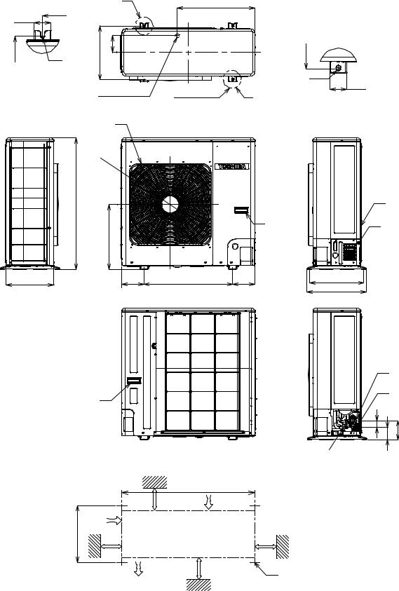
2-2. Outdoor Unit
|
|
|
A |
600 |
|
|
525 |
|
|
|
|
56.5 |
|
|
|
365 |
365 |
113 |
365 |
R6 |
|
|
|
A Detail Drawing (Back leg) |
|
|
Ø12x17 Hole |
|
|
|
56.5 |
Ø25 Drain outlet |
2-Ø12x17 Hole |
B |
B Detail Drawing (Front leg) |
|
|
|
FAN-GUARD
890 |
320 |
Ø547 |
|
|
|
|
HANDLE |
438 |
|
|
150 |
600 |
150 |
365 |
400 |
Z
PANEL-PIPING-BK
HANDLE |
Z View |
Service port |
|
|
Gas-side (Flare Ø12.70)
Liquid-side
(Flare Ø6.35)
45 |
82 |
128 |
|
600 |
200 or more |
Air inlet |
600 or more
320
150 or more |
Air outlet |
1000 or more |
|
|
4xØ17 Long holes |
Installation dimension
– 7 –

FILE NO. SVM-10049
3. WIRING DIAGRAM
3-1. RAS-24SKP-ES2 / RAS-24SA-ES2
|
|
|
1 |
2 |
3 |
|
|
|
|
POWER SUPPLY |
|
|
|
|
OUTDOOR |
|
|||
|
|
|
|
UNIT |
|
||||
220 − 240 V ~ 50 Hz |
|
|
|
|
|
||||
|
|
|
|
|
|
|
|||
OUTDOOR |
L |
N |
1 |
2 |
3 |
|
|
|
|
TERMINAL |
|
|
|
|
|||||
BLOCK |
|
|
|
|
|
|
|
|
|
|
BLK |
|
|
|
|
|
|
|
|
|
BLK |
RED |
|
|
|
|
|
|
|
|
|
|
|
CHASSIS |
|
|
|
||
|
|
RED |
|
|
|
|
|
||
|
|
|
|
|
|
|
|
|
|
|
|
BLK |
BLK |
|
GRY |
|
|
|
|
|
|
SPARK KILLER |
|
|
|
|
|
|
|
|
|
A2 52C A1 |
|
|
RED |
|
|
|
|
|
|
|
|
|
|
|
|
|
|
|
|
RED |
|
|
|
|
CAPACITOR |
WHI |
BLK |
|
|
1/L1 |
2/T1 |
RED |
|
|
RED |
||
|
|
|
|
|
|
|
|
||
|
|
|
|
CAPACITOR |
WHI |
S |
FAN MOTOR |
||
|
|
|
|
PNK |
C |
BLK |
|
||
|
|
|
|
|
|
|
|||
|
|
|
|
|
|
|
R |
|
|
|
|
5/L3 |
6/T3 |
|
|
|
COMPRESSOR |
|
|
|
|
|
|
|
|
|
|
||
MAGNETIC CONTACTOR
– 8 –

FILE NO. SVM-10049
3-2. RAS-24SKHP-ES2 / RAS-24S2AH-ES2
|
|
|
1 |
2 |
3 |
|
|
|
|
|
|
|
TRANSFORMER |
||
|
POWER SUPPLY |
|
|
|
|
BLK 1 1 |
|
|
220-240V~50Hz |
|
|
|
|
2 |
|
|
|
|
|
|
|
|
BLK 3 3 |
|
|
|
|
|
GRN&YEL |
|
RED 1 1 |
|
|
|
|
|
|
|
|
OUTDOOR |
L |
N |
1 |
2 |
3 |
|
RED 3 3 |
TERMINAL |
|
|
|||||
|
|
|
|
OUTDOOR |
|
||
BLOCK |
|
FERRITE CORE |
|
|
BLK 1 1 |
||
|
|
BLK |
|
|
UNIT |
|
|
|
|
|
|
i |
|
BLK 3 3 |
|
|
|
RED |
|
|
|
||
|
|
|
|
CHASSIS |
|
WHI 5 5 |
|
|
|
|
|
|
|
||
|
|
|
|
|
|
|
|
|
|
|
|
|
|
|
RED 7 7 |
|
BLK |
RED |
|
|
|
|
GRY 9 9 |
|
|
MAGNETIC |
|
|
|
|
|
|
|
CONTACTOR |
|
|
|
BLU 1 1 |
|
|
|
|
|
|
|
|
|
|
|
1/L1 |
|
5/L3 |
A1 |
|
YEL 3 3 |
|
|
|
|
|
|
||
|
|
|
|
|
52C |
|
BLU 1 1 |
|
|
2/T1 |
|
6/T3 |
A2 |
|
|
|
|
|
|
|
BLU 3 3 |
||
|
|
|
|
|
|
|
|
|
|
|
|
|
|
COIL FOR |
|
|
|
|
|
|
|
4 WAY VALVE |
|
|
CAPACITOR |
|
CAPACITOR |
RED |
|
RED |
|
WHI |
S |
WHI |
|
PNK |
C BLK |
RED |
BLK |
R
MAIN P.C. BOARD (MCC-890)
CN06 |
|
|
|
DISCHARGE |
|
|
|
|
|
PIPE |
|
|
|
|
|
SENSOR (TD) |
|
CN05 |
|
|
1 |
1 |
BLU |
|
|
CN07 2 |
|
|
|
SG01 |
TNR |
|
3 |
3 |
BLU |
R74 |
|
|
|
|
|
F01 |
|
|
|
|
|
250VAC T6. 3A |
TNR |
1 |
1 |
BLK |
|
|
|
R73 |
CN08 2 |
|
|
CN01 |
|
|
3 |
3 |
BLK |
|
|
|
|
HEAT |
|
|
|
|
|
EXCHANGER |
|
|
|
|
|
SENSOR (TE) |
|
|
|
RY07 |
|
|
|
CN11 |
|
|
|
|
|
|
CR11 |
RY05 |
|
|
|
|
|
|
|
|
|
CN02 |
|
|
|
|
|
|
CR12 |
|
|
|
|
CR13 |
|
RY06 |
|
|
|
|
|
|
|
|
|
|
CN03 |
|
|
|
|
|
1 |
3 |
|
|
|
|
1 |
|
|
|
|
|
BLK |
|
|
|
|
COMPRESSOR |
FAN MOTOR |
– 9 –
FILE NO. SVM-10049
4. SPECIFICATION OF ELECTRICAL PARTS
4-1. Indoor Unit (RAS-24SKP-ES2)
No. |
Parts name |
Type |
Specifications |
|
|
|
|
1 |
Fan motor (for indoor) |
MF-340-30-1RT |
DC 340V, 30W |
|
|
|
|
2 |
Thermo sensor (TA-sensor) |
——— |
10 kΩ at 25° C |
|
|
|
|
3 |
Switching Transformer (T01) |
SWT-77 |
DC7V, 12 V |
|
|
|
|
4 |
Microcontroller |
TMP87CM40ANG-6P68 |
|
|
|
|
|
5 |
Heat exchanger sensor |
——— |
10 kΩ at 25° C |
|
(TC-sensor) |
||
|
|
|
|
|
|
|
|
6 |
Line filter (L01) |
LC*SS11V-R06270 |
27mH, 600mA |
|
|
|
|
7 |
Diode (DB01) |
D3SBA60 |
4 A, 600 V |
|
|
|
|
8 |
Capacitor (C03) |
EKMH451VSN121MQ35S |
120 μF, 450 V |
9 |
Fuse (F01) |
BET6.3A |
6.3 A, 250 V |
|
|
|
|
10 |
Varistor (R09, R10) |
SR561K14DO |
560 V |
11 |
Resistor (R01) |
RF-5TK1R8 |
1.8Ω , 5W |
12 |
Louver motor |
MP24Z3T |
Output (Rated) 2 W, 16 poles, 4 phase, |
|
|
|
DC 12 V |
13 |
Relay : (RY03) |
G5NB-1A-CA |
Coil DC 12V, 16.7mA, Contact AC 250V, 3A |
|
|
|
|
4-2. Outdoor Unit (RAS-24SA-ES2)
No. |
Parts name |
Type |
Specifications |
|
|
|
|
|
Output (Rated) 2000W, 2poles, 1 phase, 220-240V 50Hz |
||
|
|
|
|
|
|
1 |
Compressor |
PA271X3CS-4MU2 |
Winding resistance (Ω) |
Red-Black |
White-Black |
|
|
|
(at 20°C) |
1.27 |
2.10 |
|
|
|
|
|
|
|
|
|
Output (Rated) 42W, 4poles, 1 phase, 220 − |
240V, 50Hz |
|
2 |
Fan motor (for outdoor) |
WLF-240-85A |
Winding resistance (Ω) |
Red-Black |
White-Black |
|
|
|
|
|
|
|
|
|
(at 20° C) |
70.5 |
120.1 |
|
|
|
|
|
|
3 |
Running capacitor |
DS451355NPQB |
AC 450V, 3.0μF |
|
|
|
(for fan motor) |
|
|
|
|
4 |
Running capacitor |
B32332I5606J063 |
AC 450V, 60μF |
|
|
(for compressor) |
|
|
|||
|
|
|
|
|
|
|
|
|
|
|
|
5 |
Magnetic contactor |
A35P |
220-240V, 50Hz |
|
|
|
|
|
|
|
|
– 10 –
FILE NO. SVM-10049
4-3. Indoor Unit (RAS-24SKHP-ES2)
No. |
Parts name |
Type |
Specifications |
|
|
|
|
1 |
Fan motor (for indoor) |
MF-340-30-1RT |
DC 340V, 30W |
|
|
|
|
2 |
Thermo sensor (TA-sensor) |
——— |
10 kΩ at 25°C |
|
|
|
|
3 |
Switching Transformer (T01) |
SWT-77 |
DC 7V, 12V |
|
|
|
|
4 |
Microcontroller |
TMP87CM40ANG-6P68 |
|
|
|
|
|
5 |
Heat exchanger sensor |
——— |
10 kΩ at 25°C |
|
(TC-sensor) |
||
|
|
|
|
|
|
|
|
6 |
Line filter (L01) |
LC*SS11V-R06270 |
27mH, 600mA |
|
|
|
|
7 |
Diode (DB01) |
D3SBA60 |
4 A, 600 V |
|
|
|
|
8 |
Capacitor (C03) |
EKMH451VSN121MQ35S |
120 μF, 450 V |
9 |
Fuse (F01) |
BET6.3A |
6.3 A, 250 V |
|
|
|
|
10 |
Varistor (R09, R10) |
SR561K14DO |
560 V |
|
|
|
|
11 |
Resistor (R01) |
RF-5TK1R8 |
1.8Ω , 5W |
12 |
Louver motor |
MP24Z3T |
Output (Rated) 2 W, 16 poles, 4 phase, |
|
|
|
DC 12 V |
4-4. Outdoor Unit (RAS-24S2AH-ES2)
No. |
Parts name |
Type |
Specifications |
|
|
|
|
|
Output (Rated) 2000W, 2poles, 1 phase, 220 − 240V, 50Hz |
||
1 |
Compressor |
PA271X3CS-4MU2 |
Winding resistance (Ω) |
Red-Black |
White-Black |
|
|
|
|
|
|
|
|
|
(at 20°C) |
1.27 |
2.10 |
|
|
|
|
|
|
|
|
|
Output (Rated) 42W, 4poles, 1 phase, 220 – 240V, 50Hz |
||
|
|
|
|
|
|
2 |
Fan motor (for outdoor) |
FG-240-42A-1 |
Winding resistance (Ω) |
Red-Black |
White-Black |
|
|
|
|
|
|
|
|
|
(at 20°C) |
70.5 |
120.1 |
|
|
|
|
|
|
3 |
Running capacitor |
DS451305NPQB |
AC 450V, 3.0µF |
|
|
(for fan motor) |
|
|
|||
|
|
|
|
|
|
|
|
|
|
|
|
4 |
Running capacitor |
B32332I5606J063 |
AC 450V, 60µF |
|
|
(for compressor) |
|
|
|||
|
|
|
|
|
|
|
|
|
|
|
|
5 |
Solenoid coil |
VHV (STF) |
AC 220 ~ 240V |
|
|
(for 4-way valve) |
|
|
|||
|
|
|
|
|
|
|
|
|
|
|
|
6 |
Thermo sensor |
TE / TD |
10kΩ at 25°C / 50kΩ at 25°C |
|
|
|
|
|
|
|
|
7 |
Magnetic contactor |
A35P |
220 ~ 240V, 50Hz |
|
|
|
|
|
|
|
|
8 |
Transformer |
TT-05 |
220 ~ 240V |
|
|
|
|
|
|
|
|
9 |
Microcontroller |
TMP47C840N |
|
|
|
|
|
|
|
|
|
10 |
Varistor (R73, R74) |
15G471K |
470V |
|
|
|
|
|
|
|
|
11 |
Fuse (F01) |
TSCR |
T6.3A, 250V |
|
|
|
|
|
|
|
|
– 11 –
FILE NO. SVM-10049
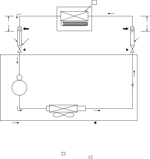
5. REFRIGERATION CYCLE DIAGRAM
5-1. RAS-24SKP-ES2 / RAS-24SA-ES2
Cooling
0.39 m (Connecting pipe)12.7
T
Indoor unit
Heat exchanger |
Cross flow fan |
0.49 m (Connecting pipe)6 .35
|
|
|
|
|
|
|
|
|
|
O.D.:12.7 mm |
|
|
P |
|
|
|
|
|
O.D.:6.35 mm |
|
Packed valve |
Packed valve |
|
|
|||||
|
|
||||||||
|
|
|
( 12.7 ) |
( 6.35) |
|
|
|
|
|
|
|
|
|
|
|
||||
|
|
Gas container connection (Reinstall etc.) |
|
|
|
|
|
||
Cooling |
|
|
|
|
Capillary tube |
Compressor |
PA271X3CS-4MUL |
2.0x450 s |
|
||
|
Heat exchanger |
|
|
|
Refrigerant |
|
Propeller fan |
R410A 1.90 kg |
Cooling |
Outdoor unit |
Mark ( |
|
) means check points of Gas Leak |
|
||||
|
|
|
Standard |
Surface temp. of heat |
|
Ambient temp. |
||
|
|
Fan speed |
conditions DB/WB |
||||
|
50 Hz |
pressure P |
exchanger interchanging |
||||
|
(indoor) |
|
(°C) |
||||
|
|
(MPaG) |
pipe T (°C) |
|
|
|
|
|
|
|
Indoor |
|
Outdoor |
||
|
|
|
|
|
|
||
|
|
|
|
|
|
|
|
|
Standard |
0.86 |
9.4 |
High |
27/19 |
|
35/24 |
|
|
|
|
|
|
|
|
Cooling |
High temperature |
1.03 |
14.3 |
High |
32/23 |
|
43/26 |
|
|
|
|
|
|
|
|
|
Low temperature |
0.65 |
1.9 |
Low |
21/15 |
|
21/15 |
|
|
|
|
|
|
|
|
Note : Measure the heat exchanger temperature at the center of U-bend. (By means of TC sensor.)
– 12 –

FILE NO. SVM-10049
5-2. RAS-24SKHP-ES2 / RAS-24S2AH-ES2
|
|
|
T1 |
|
|
|
Indoor unit |
|
Cooling |
Heat exchanger |
|
|
|
||
0.39 m |
|
Heating |
|
(Connecting pipe) |
|
||
|
|
||
Æ12.7 |
|
|
Cross flow fan |
|
|
|
|
O.D.:12.7 mm |
|
P |
|
|
|
Packed valve |
Packed valve |
|
|
(Æ12.7) |
(Æ6.35) |
 Heating
Cooling 4-way valve
Heating |
Cooling |
Compressor |
PA271X3CS-4MUL |
|
|
||
|
Discharge Muffler |
|
|
|
25x160L |
|
|
|
|
Accumulator |
|
Heat exchanger
Capillary tube Æ2.0 x 450 l
Capillary tube Æ2.0 x 700l
0.49 m (Connecting pipe)
Æ6.35
O.D.:6.35 mm
|
|
|
Refrigerant |
|
Propeller fan |
|
R410A 2.00 kg. |
Cooling |
Outdoor unit |
Mark ( |
) means check points of Gas Leak. |
Heating |
|
|
|
|
|
Standard |
Surface temp. of heat |
|
Ambient temp. |
||
|
|
Fan speed |
conditions DB/WB |
||||
|
50Hz |
pressure P |
exchanger interchanging |
(indoor) |
|
(°C) |
|
|
|
(MPaG) |
pipe T1 (°C) |
|
|
|
|
|
|
|
Indoor |
|
Outdoor |
||
|
|
|
|
|
|
||
|
|
|
|
|
|
|
|
|
Standard |
2.64 |
44.7 |
High |
20/15 |
|
7/6 |
|
|
|
|
|
|
|
|
Heating |
Overload*1 |
3.54 ~ 3.80 |
49.3 ~ 51.0 |
Low |
27/- |
|
24/18 |
|
|
|
|
|
|
|
|
|
Low temperature |
2.28 |
30.3 |
High |
20/- |
|
-10/-10 |
|
Standard |
0.90 |
11.6 |
High |
27/19 |
|
35/24 |
|
|
|
|
|
|
|
|
Cooling |
Overload |
1.10 |
17.5 |
High |
32/23 |
|
43/26 |
|
|
|
|
|
|
|
|
|
Low temperature |
0.73 |
2.6 |
Low |
21/15 |
|
21/15 |
|
|
|
|
|
|
|
|
Note
· Measure the heat exchanger temperature at the center of U-bend. (By means of TC sensor)
*1 · During heating overload operation, a value for the high temperature limit control operation is included.
- 13 -
FILE NO. SVM-10049
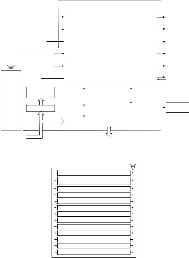
6.CONTROL BLOCK DIAGRAM
6.1RAS-24SKP-ES2 / RAS-24SA-ES2
Indoor Unit Control Panel
|
|
|
|
|
|
|
M.C.U. |
|
|
|
|
|
|
|
|
|
|
|
|
|
|
|
|
Functions |
Operation |
|
|
Heat Exchanger Sensor |
|
||||||
|
|
• |
Louver Control |
Display |
||||
|
|
|
|
|
|
|||
|
|
|
|
|
|
|||
|
|
|
|
|
|
|
|
|
|
|
|
|
|
|
• |
|
Timer |
|
|
Temperature Sensor |
|
3-minute Delay at Restart for Compressor |
||||
|
|
|
Display |
|||||
|
|
|
|
|
|
|
|
|
|
|
|
|
|
|
|
|
|
|
|
|
|
|
|
|
|
|
|
|
|
|
|
|
• |
|
Filter Sign |
Infrared Rays Signal Receiver |
|
|
Motor Revolution Control |
|||||
|
|
Display |
||||||
|
|
|
|
|
|
|
|
|
|
|
|
|
|
|
|
|
|
|
|
|
|
|
|
|
|
|
|
|
|
|
|
|
• |
|
Fan Only |
|
|
|
Initiallizing Circuit |
|
Processing |
|||
|
|
|
|
Sign Display |
||||
|
Infrared |
|
|
(Temperature Processing) |
||||
|
|
|
|
|||||
|
Rays |
|
|
|
|
|
|
|
|
Clock Frequency |
|
• |
Timer |
Hi Power |
|||
|
|
|
|
|||||
|
|
|
Oscillator Circuit |
|
Sign Display |
|||
|
|
|
|
|
|
|||
|
|
|
|
|
|
|
|
|
|
|
|
|
|
|
|
|
|
|
|
|
|
|
|
|
|
Indoor |
|
|
|
|
|
|
|
|
Fan Motor |
|
|
|
|
|
|
|
|
|
Power Supply
Circuit
Remote
Control
Noise Filter
From Outdoor Unit
240 V AC 50 Hz
REMOTE CONTROL
Outdoor unit |
|
|
Louver ON/OFF Signal |
|
||
ON/OFF Signal |
|
|
|
|
|
|
|
|
|
|
|
||
|
|
|
|
|
|
|
|
|
|
|
|
|
|
|
|
|
|
Louver Driver |
|
|
|
|
|
|
|
||
Relay Driver |
|
|
|
|||
|
|
|
|
|
||
|
|
|
|
|
||
|
|
|
|
|
||
|
|
|
|
|
|
|
|
|
|
|
|
|
|
|
|
Relay RY03 |
|
|||
|
|
|
|
|
|
|
|
|
|
|
|
|
|
|
|
Outdoor Unit |
|
|||
|
|
|
|
|
|
|
Infrared Rays
Remote Control
Operation ( )
)
Operation Mode Selection
AUTO, COOL, DRY, FAN ONLY
Temperature Setting
Fan Speed Selection
ON TIMER Setting
OFF TIMER Setting
Louver Auto Swing
Louver Direction Setting
ECO
Hi power
TIMER 1.3.5.9H
COMFORT SLEEP
QUIET
Louver Motor
– 14 –
FILE NO. SVM-10049
6.2 RAS-24SKHP-ES2 / RAS-24S2AH-ES2
Heat Exchanger Sensor
Temperature Sensor
Infrared Rays Signal Receiver
Initiallizing Circuit
Infrared
Rays Clock Frequency
Oscillator Circuit
Power Supply
Circuit
Remote
Control
Noise Filter
From Outdoor Unit
240 V AC 50 Hz
REMOTE CONTROL
Indoor Unit Control Panel
M.C.U.
Functions
• Louver Control
• 3-minute Delay at Restart for Compressor
• Motor Revolution Control
• Processing
(Temperature Processing)
• Timer
• Serial Signal Communication
Louver ON/OFF Signal
Louver Driver
Serial Signal Transmitter/Receiver
Serial Signal Communication
Infrared Rays
Remote Control
Operation ( )
)
Operation Mode Selection
Operation
Display
Timer
Display
Filter Sign
Display
PRE DEF.
Sign Display
Hi Power
Sign Display
Indoor
Fan Motor
Louver Motor
AUTO, COOL, DRY, HEAT, FAN ONLY
Temperature Setting
Fan Speed Selection
ON TIMER Setting
OFF TIMER Setting
Louver Auto Swing
Louver Direction Setting
ECO
Hi power
TIMER 1.3.5.9H
COMFORT SLEEP
QUIET
– 15 –
FILE NO. SVM-10049
7. OPERATION DESCRIPTION
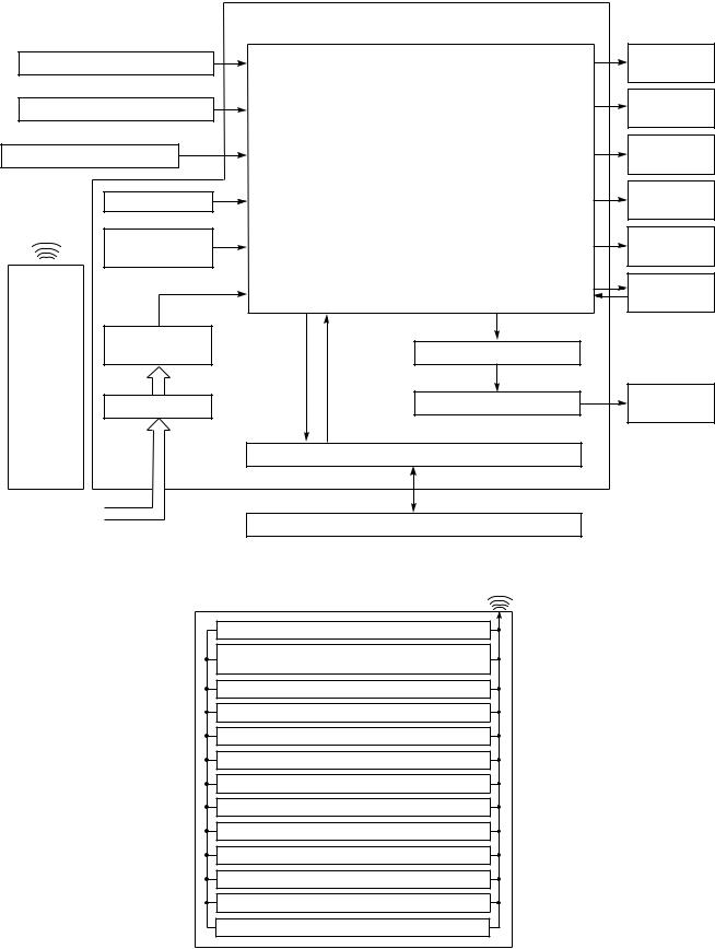
7-1. Remote control
7-1-1. Function of Push Putton
1Infrared signal emitter
2Start/Stop button
3Mode select button (MODE)
4Temperature button (TEMP)
5Fan speed button (FAN)
6Swing louver button (SWING)
7Set louver button (FIX)
8On timer button (ON)
9Off timer button (OFF)
108 Sleep timer button (SLEEP)
119 Timer setup button (SET)
2012 Timer clear button (CLR)
13Memory and Preset button (PRESET)
14One Touch button (ONE-TOUCH)
15High power button (Hi-POWER)
16Economy button (ECO)
17Quiet button (QUIET)
18Comfort sleep button (COMFORT SLEEP)
19Filter reset button (FILTER)
20Clock Reset button (CLOCK)
21 Check button (CHK)
1
13 |
PRESET |
FAN |
5 |
|
TEMP |
||
|
ONE-TOUCH |
MODE |
4 |
|
|
||
14 |
|
|
3 |
2 |
|
COMFORT |
18 |
|
QUIET |
SLEEP |
|
17 |
|
|
15 |
|
SWING FIX |
Hi-POWER ECO |
|
|
16 |
||
6 |
|
|
|
7 |
TIMER |
CLR |
12 |
8 |
ON |
OFF |
9 |
10 |
SLEEP |
SET |
11 |
21 |
CHK |
FILTER CLOCK |
20 |
|
|
|
19
− 16 −
FILE NO. SVM-10049
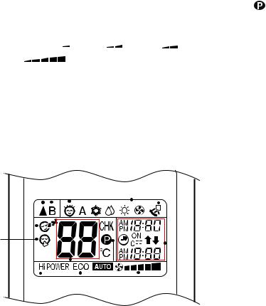
7-1-2. Display of Remote Control
All indications, except for the clock time indicator, are displayed by pressing the  button.
1. Transmission mark |
5. TIMER and clock time indicator |
This transmission mark  indicates when the remote controller transmits signals to the indoor unit.
2. Mode indicator
The time setting for timer operation or the clock time is indicated.
The current time is always indicated except during TIMER operation.
Indicates the current operation mode.
(A : Auto,  : Cool,
 : Dry,
  : Heat,
 : Fan only)
3. Temperature indicator
Indicates the temperature setting. (17°C to 30°C)
4. FAN speed indicator
Indicates the selected fan speed. AUTO or five fan speed levels
(LOW  , LOW+
  , MED
, MED  , MED+
  ,
,
HIGH |
) can be shown. |
Indicate Auto will be appear with Dry operation ( : Dry) only.
9 |
12 |
|
2 |
13 |
|||||||||
1 |
|
||||||||||||
|
|
|
|
|
|
|
|
|
|
||||
10 |
|
|
10 |
|
|
|
|
|
|
|
|
||
|
|
|
|
|
|
|
|
|
|
|
|
||
|
|
|
|
|
|
|
|
|
|
|
|
|
|
|
|
|
|
|
|
|
|
|
|
|
|
|
|
|
|
|
|
|
|
|
|
|
|
|
|
|
|
11
|
|
|
|
|
|
|
|
|
|
|
|
|
|
|
|
|
|
|
|
|
|
|
|
|
|
|
|
|
|
|
|
|
|
|
|
|
|
|
|
|
|
8 |
|
|
|
|
5 |
||
6 |
|
4 |
|||||||
|
|
|
|
|
|||||
|
|
|
|
||||||
3 |
|
7 |
|
|
|
|
|||
6. Hi-POWER indicator
Indicates when the Hi-POWER operation starts.
Press the Hi-POWER button to start and press it again to stop the operation.
7.  (PRESET) indicator
Flashes for 3 seconds when the PRESET button is pressed during operation.
The mark is shown when holding down the button for more than 3 seconds while the mark is blinks.
Press another button to turn off the mark.
8. ECO indicator
Indicates when the ECO is in activated.
Press the ECO button to start and press it again to stop operation.
9. A, B change indicator remote controller
When the remote controller switching function is set, “B” appears in the remote controller display. (When the remote controller setting is “A”, there is no indication at this position.)
10. Comfort sleep
Indicates when comfort sleep is activaled. Press comfort sleep button to selectter
11. Quiet
Indicates when quiet is activated.
Press quiet button to start and press it again to stop operation.
12. One-Touch
Indicates when one touch comfort is activated. Press one-touch button to start the operation.
13. Swing
Indicates when louver is swing.
Press swing button to start the swing operation and press it again to stop the swing operation.
− 17 −
7-2. Outline of Air Conditioner Control
This is a fixed capacity type air conditioner, which uses a DC motor for an indoor fan. The DC motor drive circuit is mounted in the indoor unit. And electrical parts which operate the compressor and the outdoor fan motor, are mounted in the outdoor unit.
The air conditioner is mainly controlled by the indoor unit controller. The controller operates the indoor fan motor based upon commands transmitted by the remote control and transfers the operation commands to the outdoor unit.
The outdoor unit receives operation commands from the indoor unit, and operates the outdoor fan motor and the compressor.
(1)Role of indoor unit controller
The indoor unit controller receives the operation commands from the remote control and executes them.
∙Temperature measurement at the air inlet of the indoor heat exchanger by the indoor temperature sensor
∙Temperature measurement of the indoor heat exchanger by the heat exchanger sensor
∙Louver motor control
∙Indoor fan motor operation control
∙LED display control
∙Transferring of operation commands to the outdoor unit
∙Receiving of information of the operation status and judging of the information or indication of error
(2)Role of outdoor unit controller
The outdoor unit controller receives the operation commands from the indoor controller and executes them.
∙ Compressor operation control
∙ Operation control of outdoor fan motor
Table 7-2-3 Indoor fan and air flow rate
|
OPERATION |
Cooling |
UH |
|
|
Fan only |
|
||
|
MODE |
|
||
|
Dry |
|
||
Model |
RAS-24SKP-ES2 |
rpm |
1340 |
|
Air flow volume (m3/h) |
1240 |
|||
|
||||
|
|
FILE NO. SVM-10049
∙Turning off the compressor and outdoor fan when the outdoor unit receives the shutdown command
∙Defrost control in heating operation (Temperature measurement by the Indoor heat exchanger, control the four-way valve and outdoor fan motor control)
7-2-1. Louver control
(1)Vertical air flow louver
Position of veritcal air flow louver is automatically controlled according to the operation mode. Besides, position of vertical air flow louver can be arbitrarily set by pressing [FIX] button.
The louver position which is set by [FIX] button is stored in the microcomputer, and the louver is
automatically set at the stored position for the next operation.
(2)Swing
If [SWING] button is pressed when the indoor unit is in operation, the vertical air flow louver starts swinging. When [SWING] button is pressed, it stops swinging.
7-2-2. Indoor Fan Control
The operation controls the fan speed at indoor unit
side. The indoor fan (cross flow fan) is operated by the phase control induction motor. The fan rotates in 5
stages in MANUAL mode, and in 5 stages in AUTO mode, respectively. (Table 7-2-3)
1)When setting the fan speed to L, L+,M, M+ or H
on the remote controller, the operation is performed with the constant speed shown in Table 7-2-1 and Table 7-2-2
Table (7-2-1) Cooling
Indication |
Fan speed |
L |
Low |
L+ |
(L + M) / 2 |
M |
Med |
M+ |
(M + H) / 2 |
H |
High |
Table (7-2-2) Heating
Indication |
Fan speed |
L |
Low |
L+ |
(L + M) / 2 |
M |
Med |
M+ |
(M + H) / 2 |
H |
High |
2) When setting the fan speed to AUTO on the remote controller, revolution of the fan motor is controlled to the fan speed level show in Table 7-2-3
according to the setup temperature, room temperature, and heat exchanger temperature.
|
|
FAN TAP |
|
|
|
|
|
H |
M+ |
M |
L+ |
L |
L- |
UL |
SL |
H |
M+ |
M |
L+ |
L |
L- |
|
|
|
M+ |
M |
L+ |
L |
L- |
UL |
SL |
|
1220 |
1100 |
1025 |
950 |
850 |
700 |
600 |
|
1120 |
1000 |
930 |
850 |
750 |
600 |
500 |
Model
|
Cooling |
|
|
|
|
|
|
FAN TAP |
|
|
|
|
|
|
|
|
|
UH |
H |
M+ |
|
M |
|
L+ |
L |
L- |
UL |
SL |
|
OPERATION |
Fan only |
|
|
|
H |
M+ |
|
M |
|
L+ |
L |
L- |
|
|
MODE |
Dry |
UH |
H |
M+ |
|
M+ |
M |
M |
L |
L+ |
L |
L- |
UL |
SL |
|
Heat |
|
|
L+ |
L- |
|
UL |
|
SL |
|||||
RAS-24SKHP-ES2 |
rpm |
|
|
1340 |
|
1220 |
1100 |
1100 |
950 |
950 |
950 |
850 |
700 |
600 |
Air flow volume (m3/h) |
|
|
1240 |
|
1120 |
1000 |
1000 |
850 |
850 |
850 |
750 |
600 |
500 |
|
|
|
|
|
- 18 -
FILE NO. SVM-10049
7-3. Description of Operation Mode
(1)When turning on the breaker, the operation lamp blinks. This means that the power is on (or the power supply is cut off.)
(2)When pressing [ ] button on the
remote control, receiving beep sounds from the indoor unit, and the next operation is performed together with opening the vertical air flow louver.
(3)Once the operation mode is set, it is memorized in the microcomputer so that the previous operation can be effected thereafter simply by pressing
[ ] button.
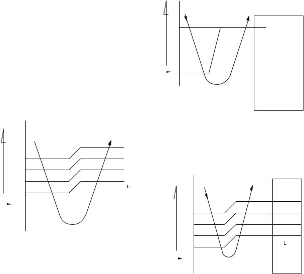
7-3-1. Fan only operation
([MODE] button on the remote control is set to the fan only operation.)
(1)When [FAN] button is set to AUTO, the indoor fan motor operates as shown in Fig. 7-3-1. When [FAN] button is set to LOW, LOW+, MED, MED+ or HIGH, the motor operates with a constant air flow.
temp.) |
|
° C |
|
|
|
|
+3 |
|
|
|
|
||
(Preset− |
|
M+ |
||||
+2 |
|
|||||
|
+2.5 |
|
|
|
|
|
|
|
*1 |
|
|||
|
|
|
|
|
||
|
|
|
|
|
|
|
temp.) |
+1.5 |
|
*2 |
|
||
|
*3 |
|
||||
(Room |
+1 |
|
|
|
|
|
|
|
|
|
|||
+0.5 |
|
|
|
|
||
|
|
|
|
|||
Preset |
|
0 |
|
|
|
|
|
|
|
|
|
||
temp. |
|
|
|
|
|
|
|
|
|
(Preset temp.: 24 °C) |
|
||
|
|
|
|
|
|
|
NOTE 1 : *1 : Fan speed = (M + −L) x 3/4 + L *2 : Fan speed = (M + −L) x 2/4 + L *3 : Fan speed = (M + −L) x 1/4 + L
2 : The Hi Power, ECO and COMFORT SLEEP operation can not be set
(Linear approximation from M+ and L)
Fig. 7-3-1 Setting of air flow [FAN:AUTO]
7-3-2. Cooling operation
([MODE] button on the remote control is set to the cooling operation.)
(1)The compressor, 4-way valve, (Heat pump model only) outdoor fan and operation display lamp are controlled as shown in Fig. 7-3-2.
temp.) |
° C |
|
|
|
||
|
|
|
|
|||
(Preset |
0.5 |
ON |
|
ON |
|
|
|
|
|||||
|
|
|
|
|
||
temp.) |
|
|
|
|
|
|
|
|
OFF |
OFF |
OFF |
ON |
|
(Room |
|
|
||||
|
|
|
|
|
|
|
Preset |
|
0 |
|
|
|
|
temp. |
|
|
Compressor |
way-4valve |
Outdoorfan |
OPERATION |
|
|
|
||||
|
|
|
|
|
|
displaylamp |
|
|
|
|
|
|
|
Fig. 7-3-2
(2)When [FAN] button is set to AUTO, the indoor fan motor operates as shown in Fig. 7-3-3. When [FAN] button is set to LOW, LOW+, MED, MED+ or HIGH, the motor operates with a constant air flow.
temp.) |
|
° C |
|
|
|
+3 |
M+ |
||||
|
|||||
(Preset |
+2.5 |
||||
*1 |
|||||
|
|||||
|
+2 |
||||
− |
*2 |
||||
|
|
||||
temp.) |
+1.5 |
*3 |
|||
|
|
|
|||
(Room |
+1 |
|
|
||
+0.5 |
|
|
|||
Preset |
|
|
|||
|
0 |
|
|
||
|
|
|
|||
temp. |
-0.5 |
|
|
||
|
|
|
|||
NOTE1 : *1 : Fan speed = (M + −L) x 3/4 + L *2 : Fan speed = (M + −L) x 2/4 + L *3 : Fan speed = (M + −L) x 1/4 + L
(Linear approximation from M+ and L)
Fig. 7-3-3 Setting of air flow [FAN:AUTO]
- 19 -
FILE NO. SVM-10049
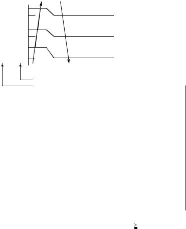
7-3-3. Dry operation
([MODE] button on the remote control is set to the dry operation.)
(1)The compressor, 4-way valve, (Heat pump model only) outdoor fan and operation display lamp are controlled as shown in Fig. 7-3-4.
7-3-4. Heating operation *Heat pump model only ([MODE] button on the remote control is set to the heating operation.)
(1)The compressor, 4-way valve, outdoor fan and operation display lamp are controlled as shown in Fig. 7-3-6.
temp.) |
° C |
|
(Preset |
+3 |
|
|
||
temp.) |
+2 |
|
|
|
|
(Room |
+1 |
|
|
|
|
Preset |
|
0 |
|
||
temp.
ON:6min. OFF:4min. |
|
ON:6min. OFF:4min. |
|
ON:5min. OFF:5min. |
OFF |
ON:5min. OFF:5min. |
ON |
|
|
||
OFF |
|
OFF |
|
|
|
|
|
Compressor |
way-4valve |
Outdoorfan |
OPERATION |
|
|
|
displaylamp |
|
|
|
|
Fig. 7-3-4
(2)The microprocessor turns the compressor on and off at the regular intervals (4 to 6 minutes). While the compressor is turning off, the indoor fan motor operates in the SUPER LOW position.
The pattern of operation depending on the relation between room temperature and preset temperatures is shown in Fig. 7-3-5.
Room temp.
Preset temp.+1
Preset temp.
Compressor |
ON |
ON |
ON |
|
ON |
||
|
|
|
|
|
|
|
|
Outdoor fan |
|
OFF |
|
OFF |
|
OFF |
|
|
|
|
|
||||
|
|
|
|
|
|
||
Indoor fan L. |
*S.L. |
L. |
S.L. |
L. |
S.L. |
L. |
|
|
*Super Low |
|
|
|
|
|
|
Fig. 7-3-5
(3)[FAN] button on the remote control is set to AUTO only.
(4)The ECO, COMFORT SLEEP, QUIET and Hi POWER operations can not be set.
|
|
° C |
|
|
|
|
|
Preset |
|
0 |
|
|
|
|
|
temp. |
|
|
|
|
|
|
|
temp.) |
|
|
|
OFF |
ON |
OFF |
ON |
(Preset |
0.5 |
|
|
|
|
|
|
|
|
|
|
|
|
||
(Roomtemp.) |
|
ON |
|
ON |
|
||
|
|
|
|
|
|||
|
|
|
|
|
|
|
|
|
|
|
Compressor |
way-4valve |
Outdoorfan |
OPERATION |
|
|
|
|
|
|
|
|
displaylamp |
|
|
|
|
|
|
|
|
Fig. 7-3-6
(2)When [FAN] button is set to AUTO, the indoor fan motor operates as shown in Fig. 7-3-7. When [FAN] button is set to LOW, LOW+, MED, MED+ or HIGH, the motor operates with a constant air flow.
° C
Preset  0 L temp. -0.5
temp.) |
-1 |
*2 |
|
-2 |
|||
|
-1.5 |
*1 |
|
|
|
||
(Preset |
|
M+ |
|
− |
|
|
|
temp.) |
-5.0 |
|
|
(Room |
-5.5 |
H |
|
[FAN AUTO] |
|||
|
|||
|
|
*1 : Fan speed = (M + −L) x 1/4 + L *2 : Fan speed = (M + −L) x 2/4 + L *3 : Fan speed = (M + −L) x 3/4 + L
(Calculated with Linear approximation from M+ and L+)
Fig. 7-3-7
- 20 -
FILE NO. SVM-10049
(3)The indoor heat exchanger restricts revolving speed of the fan motor to prevent a cold draft. The upper limit of the revolving speed is shown in Fig. 7-3-8
|
Tc |
46 |
34 |
45 |
33 |
33 |
21 |
32 |
20 |
*A+0 *A+0
*A-8 *A-8
Fan speed AUTO |
|
Fan speed MANUAL |
||
|
||||
|
|
L-H (Up to |
||
Normal AUTO |
|
setting speed) |
||
|
|
|
|
|
Line-approximate |
|
Line-approximate |
||
H and SL with Tc. |
|
H and SL with Tc. |
||
|
|
|
|
|
SL (W2) |
|
SL (W2) |
|
|
Stop |
|
Stop |
||
|
||||
Fan speed MANUAL or AUTO in starting
Fan speed AUTO in stability
*No limitation while fan speed MANUAL mode is in stability.
*A: When Tsc ≥ 24, A is 24, and when Tsc < 24, A is Tsc Tsc: Set value
[In starting and in stability]
|
In starting |
|
In stability |
|
|
|
|
FAN |
• Until 12 minutes |
• When 12 to 25 minutes |
|
AUTO |
passed after operation |
|
passed after opeartion |
|
start |
|
start and room temp. |
|
• When 12 to 25 minutes |
|
is than (set 3°C ) |
|
passed after operation |
• |
between preset |
|
start and room temp. |
When 25 minutes or |
|
|
is 3°C or lower than |
|
more passed after |
|
set temp. |
|
operation start |
|
|
|
|
FAN |
• Room temp. < Set |
• |
Room temp. Set |
Manual |
temp.–4°C |
|
temp. –3.5°C |
|
|
|
|
Fig. 7-3-8 Cold draft preventing control
7-3-5. Automatic operation
([MODE] button on the remote control is set to the automatic operation.)
(1)One of 3 operations (Cooling, Fan only or Heating) is selected according to difference between the preset temperature and the room temperature at which the automatic operation has started, as shown in Fig. 7-3-9. The Fan only operation continues until the room temperature reaches a level at which another mode is selected.
(2)Temporary Auto
When the [RESET] button on the indoor unit
is pushed, the preset temperature is fixed at 24°C and the indoor unit is controlled as shown in
Fig. 7-3-9.
°C
temp.) |
|
Cooling operation |
||
|
|
|||
(Preset |
0 |
|
|
|
Fan only operation |
||||
|
||||
− |
-1 |
|
|
|
temp.) |
|
|
||
Heating operation |
|
|||
|
|
|||
(Room |
|
|
||
|
|
|
||
|
|
Heat pump model |
Cooling model |
|
|
|
|
|
|
|
|
Fig. 7-3-9 |
||
(4)In order to prevent cold draft when compressor during heating operation.Then louver will move to upper position and fan speed will reduce or OFF.
- 21 -
FILE NO. SVM-10049
7-4. Drescription of Safety and Reliability Prevention Function
7-4-1. Low-Temperature Limit Control
The microcontroller detects the indoor heat exchanger temperature to prevent the indoor heat exchanger from freezing.
The compressor and outdoor fan motor are controlled as shown in Fig. 7-4-1.
Heat exchanger |
|
|
temperature |
Compressor Outdoor fan |
|
(°C) |
ON |
|
7 |
||
Less than 4°C continues |
||
|
||
4 |
for 5 minutes |
|
OFF |
||
|
7-4-3. Defrost Operation *Heat pump model only
When the indoor unit is in heating operation, if the refrigerant evaporation temperature detected by the outdoor heat exchanger sensor is under the specified temperature, the outdoor unit starts the defrosting operation. At this time, the 4-way valve relay and the outdoor fan motor are turned off. The indoor fan motor is also turned off by the cold draft preventing control of the indoor microcomputer. Then, [PRE. DEF.] lamp on the indoor unit comes on.
The defrosting operation stops and the 4-way valve relay, outdoor fan motor and the indoor fan motor are turned on automatically when the refrigerant evaporation increases to the specified temperature, or when the defrosting time is over 12 minutes.
Fig. 7-4-1
7-4-2 High-Temperature Limit Control
*Heat pump model only
The microcontroller detects the indoor heat exchanger temperature to prevent pressure of a refrigerating cycle from increasing excessively.
The compressor and outdoor fan motor are controlled as shown in Fig. 7-4-2.
Compressor |
Outdoor fan |
Heat exchanger |
|
temp. |
|||
|
|
OFF |
OFF |
(°C) |
|
62 |
|||
|
|
||
ON |
OFF |
55 |
|
|
|
||
ON |
ON |
54 |
|
|
Fig. 7-4-2
7-4-3-1. Defrost starting condition
A-Zone : If -10°C > Teo ³- 18°C, defrost will start when.
Teo - Te ³2.5°C at teat 20 sec or ~ 30 min after operation.
B-Zone : If Te £ -18°C, defrost start instantaneously (Suddenly) 00 ~ 25 min ofter operation
C-Zone : If -2ºC ³ Teo ³-10°C defrost will start when Teo - Te £ -3°C at least 20 sec or ~ 60 min after operation.
7-4-3-2. Defrost finish condition.
1)If Te ³ 3°C at least 60 sec -->4 way value on.
2)If Te ³ 8°C --> 4 way value on.
Timing
Operation time (4 Loops = Tt)
|
|
|
|
|
Td1 |
|
|
|
Td2 |
|
|
|
Td3 |
|
|
|
Td4 |
|
|
|
|
|
|
|
|
|
|
|
|
|
|
|
|
||||
|
|
|
|
|
|
|
|
|
|
|
|
|
|
|
|
|
|
|
|
|
|
|
|
|
|
|
|
|
|
|
|
|
|
|
|
|
|
Start time record |
Finish time record |
Defrost time rate : (Td/Tt) x 100
Heating time rate : (Tt - Td) x Tt
Fig. 7-4-3
- 22 -
FILE NO. SVM-10049
7-5. One-Touch Operation
(Heatpump Model : RAS-24SKHP-ES2)
One touch comfort is the fully automated operation that is set according to the preferable condition in a region.
Fan |
|
|
|
Operation |
AUTO |
*AUTO/L |
L |
|
0 |
12 |
25 |
Time after operation |
starts (min) |
Fig. 7-5-1
*AUTO/L : Fan operates depends on the setting temperature and room temperature.
During the One Touch Comfort mode if the indoor unit receives any signal with other operation mode, the unit will cancel the comfort mode and operates according to the signal received.
Operation description
When an indoor unit receives "One Touch Comfort Signal" from the remote controller, the indoor unit operates as following.
1)Air conditioner starts to operation when the signal is received, even if the air conditioner was OFF.
2)Operation mode is set according to room temperature, the same as AUTO mode.
3)Target temperature is 24ºC.
4)Louver position is set as stored position.
(Cooling Only Model : RAS-24SKP-ES2)
One touch comfort is the fully automated operation that is set according to the preferable condition in a region.
Fan |
|
|
Operation |
Hi-POWER |
*AUTO/L |
0 |
12 |
25 |
Time after operation |
starts (min) |
Fig. 7-5-2
*AUTO/L : Fan operates depends on the setting temperature and room temperature.
During the One Touch Comfort mode if the indoor unit receives any signal with other operation mode, the unit will cancel the comfort mode and operates according to the signal received.
Operation description.
When an indoor unit receives "One Touch Comfort Signal" from the remote controller, the indoor unit operates as following.
1)Air conditioner starts to operation when the signal is received, even if the air conditioner was OFF.
2)Operation mode is set Cooling mode.
3)Target temperature is 22ºC.
4)Louver position is set swing.
5)Fan is controlled as diagram.
-23 -
Loading...